
Instructions / Assembly


Operating Instructions and Parts Manual
6
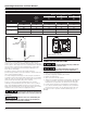
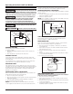
Figure 2
Illustration C
DRIVE POINT
TO PUMP
IN-LINE
CHECK VALVE
• If wire run is a short distance, a cord/plug assembly may be
used as long as it meets the minimum wire gage size, called out in
Chart 3, above. Time delay fuses are recommended over standard
fuses for motor circuit protection. All pump motors have built-in
automatic overload protection that will prevent damage to the
motor due to overheating.
• Do NOT connect to electric power supply until unit is
permanently grounded. Connect ground wire to approved ground
then connect terminal provided.
• A metal underground water pipe or well casing at least 10 feet
long makes the best ground electrode. If plastic pipe or insulated fi
ttings are used, run a wire directly to the metal well casing or use a
ground electrode furnished by the power company.
• There is only one proper ground terminal on the unit. The
terminal(s) is located under the pressure switch cover, is painted
green and is identified as GRD. The ground connection must be
made at this terminal (Figure 3). The ground conductor must not be
smaller than the circuit conductors supplying the motor.
Disconnect power and release all pressure from
the system before attempting to install, service, relocate or perform any
maintenance.
Débrancher de la source d’alimentation puis
dissiper toute la pression du système avant d’essayer d’installer, de
réparer, de déplacer ou de procéder à l’entretien.
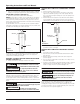
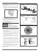
L2
3
L1
1
Figure 3 - Electrical Connections
MOTOR
LINE
GROUND SCREW
OPERATION
PRIMING THE SHALLOW WELL PUMP
To prevent damage to the pump, do NOT start
motor until pump has been filled with water.
Pour éviter d'endommager la pompe, ne pas
démarrer le moteur tant que la pompe n'a pas été remplie d'eau.
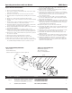
1. Remove prime plug (Figure 4).
2. Fill pump and piping completely full of water.
3. Replace the prime plug.
4. Open a faucet to vent the system.
5. Start the motor. Water will pump in a few minutes. If pump fails
to prime in 5 minutes, stop motor and refill pump with water.
Priming time is proportional to the amount of air in inlet pipe.
6. Let the system operate for several minutes to flush all pipes.
7. Close faucet and allow pump to build pressure in tank. When
the pressure reaches the cut-out setting, the motor will stop.
The system is now in operation and will automatically cycle on
demand.
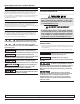
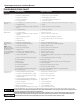
CHART 3 - RECOMMENDED FUSING & WIRING DATA - 60 HZ MOTORS
HP VOLT
Dual
Element
Fuse
250V
Distance in Feet From Meter to Motor
0
to
50
51
to
100
101
to
200
Wire Size
1/2
115 20 14 12 10
230 10 14 14 14
3/4
115 20 14 12 8
230 10 14 14 14
1
115 20 12 10 8
230 10 14 14 14
* above is the suggested size only. Check with local or state code for proper sizing.
ELECTRICAL (CONT'D)