
Instructions / Assembly


Operating Instructions and Parts Manual
8
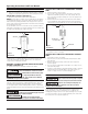
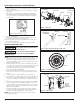
Figure 8 - Shaft Seal
CAP SCREWS
DIFFUSER
PUMP HOUSING
(VOLUTE)
CAP SCREWS
SEAL PLATE
MOTOR
IMPELLER
VENTURI
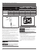
Figure 9 - Removing Shaft Seal and Ceramic Seat
ROTATING SHAFT
SEAL MEMBER
SEAL PLATE
CERAMIC SEAT
IMPELLER
RUBBER SEAT RING
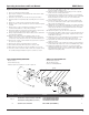
Figure 10 - Seal Plate Replacement
SCREW
MOTOR
Figure 11 - Motor Shaft
SEAL PLATE
SEAL FACE
MUST BE
CLEAN FOR
PROPER SEAL
SEAL PLATE
MOTOR
IMPELLER
SEAL SEAT
5. Remove the two cap screws and diffuser from the seal plate to
expose the impeller.
6. Remove the small end cap on the end of the motor opposite
the impeller.
7. With a large screwdriver, keep the shaft from rotating and
remove the impeller by hand (standard right hand thread). Be
sure to hold onto the seal plate when removing the impeller
from the shaft.
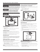
Figure 7 - Voltage Selector
1
1
5
V
8. Remove the seal plate.
9. Pry the rotating shaft seal member (including stainless collar
and rubber seal) from the impeller (Figure 9).
10. Push or pry the ceramic seat, and rubber seat ring free from
the seal plate (Figure 9).
11. Remove loose particles from impeller hub and seal plate.
INSTALLING NEW SHAFT SEAL
Before handling shaft seal parts wipe hands
clean. Dirt or grease MAY damage the seal.
Se laver les mains avant de manipuler les
pièces du joint de l'arbre. La poussière ou la graisse POURRAIT
endommager le joint.
NOTE: Be careful not to scratch the ceramic surface of the seal
seat and push seat enclosed in rubber into seal cavity on seal
plate. Use a cardboard washer to protect polished surface
when pushing against ceramic seat with any object. Be sure to
remove cardboard washer.
2. Carefully slip seal plate over shaft. Do not disturb seal position
in seal plate. The seal plate must be orientated during assembly
so the two screw holes are on a horizontal line across the
motor shaft (Figure 10). This placement should be done to
ensure proper draining and priming.
3. Place rotating shaft seal member in position on impeller and
press into place. Take care not to press against polished seal
surface.
4. Position impeller on shaft and tighten securely (Figure 11).
5. Secure diffuser to seal plate using the two cap screws. Be sure
the arrow on the front of the diffuser is pointing up and the
screws are orientated on a horizontal line as described in Step
2.
6. Carefully position pump housing (volute) gasket over the diffuser
onto the seal plate. In all shallow well applications care must
be taken that the o-ring is clean and properly positioned on the
venturi. Cleaning and positioning makes a good seal inside the
diffuser when assembled.
7. Assemble the pump housing (volute) to the motor using the
four cap screws. Be sure the pump housing (volute) gasket is
positioned correctly and tighten the screws securely.
NOTE: Shaft must rotate freely and motor end cap should be
secured before operation.