
Instructions / Assembly


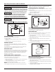

Operating Instructions and Parts Manual
9
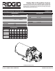
RSWS Series
Address any correspondence to:
RIDGID Water Systems
101 Production Drive
Harrison, OH 45030 U.S.A.
Please provide following information:
- Model number
- Serial number (if any)
- Part description and number as shown in parts list
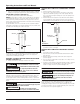
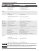
Ref. No. Description Part No. Qty.
1, 2, 3
Kit (Gaskets, impeller, Venturi, Jet Nozzle,
Shaft Seal Assembly, Diffuser, Screws)
1/2 HP RSWS50 64043-WYN1
3/4 HP RSWS75 64044-WYN1
1 HP RSWS100 64045-WYN1
1
4 30/50 Pressure Switch Kit 64031-WYN1 (ALL MODELS) 1
1, 2, 3
4
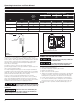
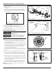
Replacement Part Kit Installation
1. Disconnect all power from the pump
2. Open faucet nearest the tank and allow all of the water to drain
from the tank and pump.
3. Remove 4 cap screws, do not disconnect pressure switch.
4. Remove pump housing from pump assembly, move it out of the
way.
5. Using a ¾” socket remove venturi from pump housing
6. Using a 11/16" socket and extension remove nozzle from pump
housing
7. Using a 5/16” socket or flat blade screw driver remove the 2
screws from the diffuser on the pump assembly.
8. Remove the diffuser, and remove the black plastic cap from the
back of the motor, exposing the motor shaft end.
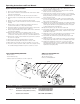
9. Using a large flat bladed screw driver hold the motor shaft while
unscrewing the impeller.
10. Remove the shaft seal from the impeller, make sure the
stainless steel sleeve comes off the impeller, all you should see
on the back of the impeller is the brass colored threaded insert.
11. Remove the ceramic seat and rubber boot part of the seal from
the cast iron seal plate.
12. Remove the square cut gasket from the seal plate.
13. Reassemble the pump with new parts in reverse order.
14. Wipe down the seal plate to remove any debris or loose rust.
15. Push the ceramic seat of the shaft seal into the seal plate using
the cardboard ring provided to keep the ceramic face clean.
You can use a little water or dish soap to lubricate the seal
pocket to make assembly easier.
16. Slide the square cut gasket over the flange on the seal plate,
make sure not to let the gasket twist.
17. Carefully slip the seal plate over the shaft so as not to disturb
seal position in the seal plate. The seal plate must be orientated
during assembly so the two holes are on a horizontal line
across the motor shaft.
18. Push the bellows side of the shaft seal over the impeller hub,
you can use a little water or dish soap to lubricate the impeller
hub to make assembly easier.
19. Holding the motor shaft with a flat blade screw driver thread the
impeller onto the motor shaft, hand tighten. Lubricate the nose
of the impeller with Dow Corning III valve lubricant and sealant
or other potable water safe lubricant.
20. Replace the plastic cap over the motor shaft end.
21. Reassemble the diffuser, make sure the arrow indicating the top
is pointed toward the top of the pump, torque the two screws
to 30 ±10 inch pounds.
22. Using the 11/16” socket and extension reassemble the nozzle
to the pump housing, torque to 50 ± 10 inch pounds.
23. Reassemble the Venturi to the pump Housing, torque to 50
±10 inch pounds.
24. Using the (4) cap screws reattach the pump housing and base
to the pump body. Torque the screws to 140 ±40 inch pounds.
25. Reattach the plumbing connections, reconnect the power
and prime the pump (See section on priming the pump). After
reassembling the pump check for leaks. If a leak is detected,
repair before using the pump.