
Warranty


Operating Instructions and Parts Manual
4
PRE-INSTALLATION (CONT'D)
SURFACE WATER
Water from a lake, storage tank, stream, pond and/ or cistern. This
water is usually not fit for human consumption, but may be suitable
for washing, irrigation or other household uses.
GROUND WATER
Water found in the water bearing stratum at various levels beneath
the earth. Of all the fresh water found on earth only 3 percent is
found on the surface and 97 percent is underground.
WATER STORAGE
Tanks are required for these pumps to operate as designed.
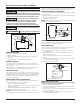
TANKS - CONVENTIONAL STORAGE
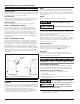
The function of the tank is to store a quantity of water under
pressure. When full, the tank contains approximately 2/3 water
and 1/3 compressed air. Then compressed air forces the water
out of the tank when a faucet is opened. An air volume control
automatically replaces air lost or absorbed into the water. The
usable water, or drawdown capacity, of the tank is approximately
1/6 of the tanks total volume when operated on a 30/50 pressure
setting (Figure 1).
TANKS - PRECHARGED STORAGE
A precharged storage tank has a fl exible bladder or diaphragm
that acts as a barrier between the compressed air and water. This
barrier prevents the air from being absorbed into the water and
allows the water to be acted on by compressed air at initially higher
than atmospheric pressures (precharged). More usable water is
provided than with a conventional type tank. Precharged tanks are
specifi ed in terms of a conventional tank. For example, a 20 gallon
precharged tank will have the same usable water or drawdown
capacity as a 40 gallon conventional tank, but the tank is smaller in
size (Figure 1).
DISCHARGE
HOSE
AIR VOLUME
CONTROL
Figure 1 - Conventional & Precharged Storage Tanks
BLADDER
PRECHARGED TANK
CONVENTIONAL TANK
INSTALLATION
LOCATION
Select a location as close to the water supply as possible. Be sure
to comply with any state or local codes regarding the placement
of the pump. The equipment must be protected from the elements
or voids warranty. A basement or heated pump house is a
good location. Make sure the pump has proper ventilation. The
temperature surrounding the pump is not to exceed 100° F (38°C)
or nuisance tripping of the motor overload may occur.
WELLS
A new well should be pumped clear of sand before installing the
pump. Sand will damage the pumping parts and seal. The draw-
down level of the well should not exceed the maximum rated depth
for the pump. The capacity of the pump will be reduced and a loss
of prime may occur.
PIPING
Inlet piping may be copper, steel, or rigid PVC plastic.
Flexible pipe is prohibited on suction pipe
(inlet pipe).
MISE EN GARDE
Un tuyau flexible est interdit sur le tuyau
d'aspiration (tuyau d'entrée).
The pipe must be clean and free of rust or scale. Use a pipe joint
compound on the male threads of the metal pipe. Plumber’s seal
tape should be used with plastic threads. All connections must be
air tight to insure normal operation.
Slope all inlet piping upwards towards the pump to prevent
trapping air. Unions or hose couplings can be installed near pump
to facilitate removal for servicing or storage. A rubber hose installed
between the water system and the house piping will reduce the
noise transmitted to the house.
PRESSURE SWITCH
The pressure switch provides for automatic operation.
The pump starts when pressure drops to a cut-in setting. The
pump stops when pressure reaches a cut-out setting.
The pressure switch is preset and is NOT adjustable.
PIPE SIZES
Long horizontal pipe runs and an abundance of fittings and
couplers decrease water pressure due to friction loss. See Chart 2
below to determine the proper pipe size.
CHART 2 - PIPE SIZING
Pump Model Pump Opening 0-25 26-100 100-300
Shallow Well Inlet 1-1/4 in. 1-1/2 in. 2 in.
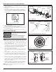
SHALLOW WELL INSTALLATION
A shallow well pump can be used when the pump is located less
than 25 feet vertically of the water level. Shallow well pumps have
only one pipe between the pump and the water supply (Figure 2).
DRILLED WELL (FIGURE 12 ON PAGE 11)
1. Install a foot valve on the first section of pipe (Figure 2,
Illustration A).
2. Lower the pipe into the well.
3. Add pipe until the foot valve is 5 feet below the lowest
anticipated water level.
The foot valve MUST be at least 18” from the
bottom of the well or sand or sediment WILL be drawn into the system.
MISE EN GARDE
Le clapet de pied DOIT au moins être
à 45,7 cm (18po) du fond du puits, sinon du sable ou des sédiments
POURRAIENT être aspirés dans le système
4. After proper depth is reached, install a well seal or pitless
adapter to support pipe and prevent surface water and other
contaminants from entering well.