INTRODUCTION Congratulations on purchasing a UPS Sentinel Pro product and welcome to Riello UPS! To use the support service offered by Riello UPS, visit the site www.riello-ups.com The company is highly specialised in the development and production of uninterruptible power supplies (UPSs). The UPSs in this series are high-quality products, carefully designed and manufactured in order to ensure the highest levels of performance.
CONTENTS PRESENTATION 5 UPS VIEWS 6 FRONT VIEW 6 REAR VIEW 6 DISPLAY PANEL VIEW 8 BATTERY BOX (ACCESSORY NOT PROVIDED WITH UPS) 9 REAR VIEW 9 INSTALLATION 10 INITIAL CONTENT CHECK 10 INSTALLATION ENVIRONMENT 11 BATTERY BOX INSTALLATION 11 SETTING THE NOMINAL BATTERY CAPACITY 11 USE 12 CONNECTIONS AND SWITCHING ON FOR THE FIRST TIME 12 SWITCHING ON FROM THE MAINS 12 SWITCHING ON FROM THE BATTERY 12 SWITCHING OFF THE UPS 12 DISPLAY PANEL MESSAGES 13 UPS STATUS MESSAGES 13
TROUBLESHOOTING 20 ALARM CODES 22 FAULT 22 LOCK 23 TECHNICAL DATA 24 4
PRESENTATION SENTINEL PRO uses ON-LINE double conversion technology, resulting in the highest levels of reliability and maximum protection for critical loads such as servers, IT applications and Voice/Data. It is possible to use one or more autonomy expansion units known as BATTERY BOXES (optional accessories) with the same dimensions and aesthetic line as the UPS alongside it.
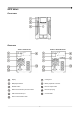
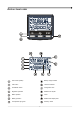
UPS VIEWS FRONT VIEW REAR VIEW 700VA / 1500VA model 1000VA / 1000VA ER model Display Cooling fans Multipurpose buttons Battery expansion connector ON/OFF switch IEC 10A output socket RS232 communication port and contacts IEC 10A input plug USB communication port Circuit breaker Slot for communication cards 6
2200VA model 2200VA ER / 3000VA / 3000VA ER model RS232 communication port and contacts IEC 16A output socket (only for 3000VA models) USB communication port IEC 10A output socket Slot for communication cards IEC 16A input plug Cooling fans IEC 10A input plug Battery expansion connector Circuit breaker 7
DISPLAY PANEL VIEW “SEL” button (Select) Battery charge indicator “ON” button Load level indicator “STAND-BY” button Configuration area Regulation operation Maintenance request Mains operation Timer Battery operation Measurement display area Load powered by bypass Stand-by / alarm 8
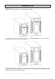
BATTERY BOX (ACCESSORY NOT PROVIDED WITH UPS) The BATTERY BOX is an optional accessory dedicated to this range of UPSs (same dimensions and aesthetic line). The BATTERY BOX contains batteries which allow the operating time of the uninterruptible power supplies to be increased during extended blackouts. The number of batteries contained can vary according to the type of UPS for which the BATTERY BOX is intended.
INSTALLATION INITIAL CONTENT CHECK After opening the packaging, it is first necessary to check the contents.
INSTALLATION ENVIRONMENT The UPS and the Battery Box must be installed in ventilated, clean environments which are sheltered from bad weather. The relative humidity in the environment must not exceed the maximum values shown in the Technical Data table. The ambient temperature, whilst the UPS is in operation must remain between 0 and 40°C, and the UPS must not be positioned in places which are exposed to direct sunlight or to hot air.
USE CONNECTIONS AND SWITCHING ON FOR THE FIRST TIME 1) Check that there is a protection device against overcurrents and short circuits in the system upstream from the UPS. The recommended protection value is 10A (for the 700VA, 1000VA and 1500VA versions) and 16A (for the 2200VA, 3000VA and ER versions) with a B or C trip curve. 2) Power the UPS using the input cable provided. 3) Press the ON/OFF switch located on the front panel.
DISPLAY PANEL MESSAGES This chapter describes, in detail, the various information that can be displayed on the LCD. UPS STATUS MESSAGES ICON STATUS Fixed Flashing DESCRIPTION Indicates a fault The UPS is in stand-by mode Fixed Indicates regular operation Fixed The UPS is operating from the mains Flashing The UPS is operating from the mains, but the output voltage is not synchronised with the mains voltage Fixed The UPS is operating from the battery.
MEASUREMENT DISPLAY AREA It is possible to display the most important measurements regarding the UPS in sequence on the display. When the UPS is switched-on, the display shows the main voltage value. To display a different measurement, press the “SEL” button repeatedly until the desired measurement appears. In the event of a fault/alarm (FAULT) or a lock (LOCK), the display will automatically show the type and code of the corresponding alarm.
CONFIGURING THE OPERATING MODE The area of the display shown in the figure displays the active operating mode and allows the user to choose other modes directly from the display panel. HOW TO PROCEED: • To access the configuration area, hold down the “SEL” button for at least 3 seconds. • The icon corresponding to the mode currently set lights up. • To change the mode, press the “ON” button. • To confirm the mode chosen, hold down the “SEL” button for at least 3 seconds.
SOFTWARE RS232 PC UPS USB MONITORING AND CONTROL SOFTWARE The PowerShield3 software guarantees effective, intuitive UPS management, displaying all the most important information such as input voltage, applied load, battery capacity. It is also able to perform shutdown operations and send e-mails, text messages and network messages automatically when certain events, selected by the user, occur.
UPS CONFIGURATION The table below illustrates all the possible configurations available to the user in order to best adapt the UPS to individual requirements. It is possible to perform these operations using the Upstools software.
FUNCTION DESCRIPTION DEFAULT POSSIBLE CONFIGURATIONS Bypass voltage thresholds Selects the permitted voltage range for switching to the bypass Low: High: 180V 264V • Low: 180 - 200 in 1V steps • High: 250 - 264 in 1V steps Selects the permitted Bypass voltage voltage range for operation threshold for ECO in ECO mode Low: High: 200V 253V • Low: 180 - 220 in 1V steps • High: 240 - 264 in 1V steps Intervention sensitivity for ECO Selects the intervention sensitivity during operation in ECO mode
COMMUNICATION PORTS On the back of the UPS (see UPS Views), the following communication ports are present: • RS232 connector • USB connector • Expansion slot for additional communication cards RS232 CONNECTOR RS232 CONNECTOR PIN # 1 2 3 4 5 6 7 8 9 SIGNAL Programmable output *: [default: UPS in lock] TXD RXD Programmable input **: [default: disabled] GND Power supply DC (Imax = 20mA) Programmable input **: [default: disabled] Programmable output *: [default: low battery pre-alarm] Programmable outpu
TROUBLESHOOTING Irregular UPS operation is most likely not an indication of a fault but due to simple problems or distraction. It is therefore advisable to consult the table below carefully as it summarises information which is useful for solving the most common problems. PROBLEM POSSIBLE CAUSE SOLUTION ON/OFF SWITCH NOT PRESSED Press the ON/OFF switch on the front panel. MAIN CONNECTION CABLE Check that the power cable is connected correctly.
PROBLEM POSSIBLE CAUSE SOLUTION THE BUZZER SOUNDS CONTINUOUSLY AND THE DISPLAY SHOWS ONE OF THE FOLLOWING CODES: A54, F50, F51, F52, F55, L50, L51, L52 THE LOAD APPLIED TO THE UPS IS TOO HIGH Reduce the load to within the threshold of 100% (or user threshold in the case of code A54). If the display shows a lock: remove the load and switch the UPS off and back on again.
ALARM CODES Using a sophisticated self-diagnosis system, the UPS is able to check its own status and any anomalies and/or faults which may occur during normal operation and display them on the display panel. If there is a problem, the UPS signals the event by showing the code and the type of active alarm on the display (FAULT and/or LOCK).
¾ Active commands: Indicates the presence of an active remote command.
TECHNICAL DATA UPS MODELS SEP 1000 SEP 1000 ER SEP 700 SEP 1500 SEP 2200 SEP 2200 ER SEP 3000 SEP 3000 ER 9.5 12.5 INPUT Nominal voltage [Vac] 220 - 230 - 240 Maximum operating voltage [Vac] 300 Nominal frequency [Hz] 50 - 60 Nominal current (1) [A] BATTERY Recharge time (standard versions) Expandability and nominal voltage of the Battery Box Charging current (for ER versions only) 3.3 4.5 6.
BATTERY BOX JSEP036-NPA- JSEP036-NPM- JSEP072-NPA- JSEP072-NPM- Nominal battery voltage [Vdc] 36Vdc 72Vdc Dimensions W x D x H [mm] 158 x 422 x 235 190 x 446 x 333 Weight [kg] 14 21 The “-” symbol replaces an alphanumeric code for internal use.
0MNSEP700RUENUC