Installation & Operating Manual Two stage operation forced draught natural gas/propane burner The following pages contain information, descriptions and diagrams for the proper installation and wiring of the burner. Please read carefully before attempting final installation. This manual is to remain with the final installation designation.
GB TABLE OF CONTENTS Installation instructions and owner's handbook . . . . . . . . . . . . . . . . . . . . . . . . . . . . . . . . . . . . . . . . . . . . . . . . . . . 2 General information . . . . . . . . . . . . . . . . . . . . . . . . . . . . . . . . . . . . . . . . . . . . . . . . . . . . . . . . . . . . . . . . . . . . . . . 3 Step by step procedure. . . . . . . . . . . . . . . . . . . . . . . . . . . . . . . . . . . . . . . . . . . . . . . . . . . . . . . . . . . . . . . . . . . . .
GB INSTALLATION INSTRUCTIONS AND OWNER'S HANDBOOK CAUTION: All gas burners MUST be installed by trained and licensed technicians. WARNING: Installation of this burner must conform with local codes requirements or, in the absence of local codes, with the Standard: National Fuel Gas code ANSI Z223.1-1984, and CAN/CGA B149.1 & 2 AND UL 795.
GB GENERAL INFORMATION Your Riello gas burner comes to you completely assembled and factory wired, ready for installation. Models equipped with the short combustion head have a fixed flange, which bolts directly to the front of the appliance. When equipped with the long combustion head, the burner comes with a universal flange, which when bolted to the appliance, allows the burner to be adjusted for exact positioning in the combustion zone.
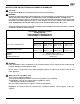
GB 10) Always do a final set up by checking the gas flow rate by clocking the meter. Do a complete combustion check with proper test equipment to obtain the best and safe CO² , O², and CO results. This test must be done by a qualified technician. The maximum CO² level for Natural Gas is 10%. The maximum CO² level for Propane Gas is 12%. The recommended flue gas temperature is from 350 degrees Fahrenheit to 550 degrees Fahrenheit.
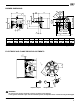
GB BURNER DIMENSIONS B G G1 7 7/8” - 200 mm 4 31/32” 128 mm J I E A H L ° 60 45° 30° F D7334 D 6 17/32”-166 mm 8 1/4” - 210 mm C Model 900 A B C D inches 47 25 41 19 mm 11 /64 13 298 /32 2 350 /64 67 1 /64 33 9 1/4” - 235 mm E 3 /4 19 15 D7351 F G G1 H I J L 23 23 5 59 63 1 47 /64 4 389 /32 120 10 /8 270 4 /64 125 5 /64 152 9 /16 230 3 /64 95 NOTE: Actual available insertion length must be measured from tip of end cone to face of mount
GB TYPICAL GAS TRAIN LAYOUT This gas train scope of supply meets the minimum controls requirements according to CGA and AGA regulations. Any additional requirements needed to meet local codes are the responsibility of others.
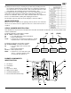
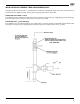
GB INSTALLING THE BURNER A) B) 1) 2) 3) 1 3 2 Burner Chassis Combustion Head Assembly Locking Nut Mounting Plate surface Insulation Gasket Separate the combustion head of the burner from the chassis (A) by removing the locknut (1). Install the combustion head into the boiler. Typical insertion depth, the front edge of the combustion head is flush with the inside surface of the appliance mounting surface (2).
GB INSTALLATION OF SEDIMENT TRAP AND BURNER SUPPLY Gas piping to the burner must be 1/2-inch minimum. Install only a full-ported shutoff valve. The valve must be located outside the appliance jacket, and the pressure gauge port must be accessible. PRESSURE TEST-OVER 1/2 PSIG. The appliance and its individual shutoff valve must be disconnected from the gas supply piping system during any pressure testing of the system at a test pressure in excess of 1/2 PSIG.
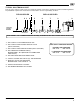
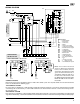
GB WIRING DIAGRAM SM SO CN1 M ST1 CN2 14 TA NO NC ST0 B P PA 6 9 11 12 A RMG... C N4 TB 13 7 1 5 ST2 CARRIED-OUT IN THE FACTORY 2 10 8 15 16 17 N3 N5 1 2 3 0 M CN6 MV CN5 C CN4 D7604 F TO BE DONE BY THE INSTALLER 1 2 3 4 5 6 SINGLE STAGE BURNER - LOW FIRE START 7 8 9 10 11 12 TWO STAGE BURNER FIRING 1 2 3 4 5 6 7 8 9 10 11 12 1 2 3 4 5 6 7 8 9 10 11 12 7 8 4 5 10 11 Wiring legend C - Capacitor MV F - Fuse 6.25A CN...
GB COMBUSTION HEAD SETTING To set combustion head, loosen the Allen screw (A) and move the elbow (B) so that the rear edge of the air tube (C) coincides with the set point number. Retighten the Allen screw (A). Make sure you are using the correct table for either Natural gas or Propane gas.
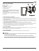
N5 N3 ST2 PRELIMINARY BURNER ADJUSTMENTS STANDBY WAITING FOR CALL FOR HEAT DO NOT ADJUST THIS SETTING FOR ANY REASON!!! The ST0 lever is set at the factory and corresponds to the air gate shut position of zero on the. N4 ST0 ST1 GB D7342 1st STAGE (LOW FIRE) AIR DAMPER SETTING The ST1 lever controls the first stage position of the air damper and must be set at a higher degree setting than the ST0 Lever.
GB COMBUSTION CHAMBER SIZE COMBUSTION CHAMBER SIZE Recommended Minimum Sizes Length - Inches 40 36 32 R ETE M A DI 28 24 20 16 440 280 600 760 920 KBtu/h NOTES: 1) Sizes shown above are for cylindrical or wet base boilers, or air cooled heat exchangers. 2) To size the chamber in applications other than wet base boilers, you must calculate area in square inches of the combustion zone required to give you a grate area or floor area to match the BTU inputs according to local authority.
GB START-UP CYCLE DIAGNOSTICS During start-up, indication is according to the followin table: COLOUR CODE TABLE Sequences Colour code Pre-purging ● ● ● Ignition phase ● ❍ ● ● ● ❍ ● ● ● ❍ ● ● ● ❍ ● ● ● ❍ ● ❑ ❑ ❑ ❑ ❑ ❑ ❑ ❑ ❑ ❑ ❑ ❑ Operation, flame ok ❑ ❍ ❑ ❍ ❑ ❍ ❑ ❍ ❑ ❍ Operating with weak flame signal.
GB SOFTWARE DIAGNOSTICS Reports the life of the burner by means of an optical link with the PC, indicating hours of operation, number and type of lock-outs, serial number of control box etc ... To view diagnostics, proceed as follows: Hold the button down for more than 3 seconds once the red LED (burner lock-out) remains steadily lit. A yellow light pulses to tell you the operation is done. Release the button for 1 second and then press again for over 3 seconds until the yellow light pulses again.
GB PROBLEM SOLVING GUIDE Burner starting difficulties and their causes: 1) The burner goes to lockout after the prepurge period because the flame does not ignite. a) Air has not been fully evacuated from the gas lines. b) The gas valve is passing too little gas. c) The ignition spark is irregular or not present. d) The gas valve is defective. 2) The burner does not start when there is a call for heat. a) The air pressure switch has failed to return to n.c. contacts.
GB SPARE PARTS 3245 16
GB SPARE PARTS LIST No. CODE DESCRIPTION No.
2165 Meadowpine Blvd. Mississauga,On L5H 3R2 Phone: 905-542-0303 Toll Free: 800-387-3898 Fax: 905-542-1525 35 Pond Park Rd. Hingham, MA 02043 Phone: 781-749-8292 Toll Free: 800-992-7637 Fax: 781-740-2069 BURNER START- UP FORM * Appliance: Burner S/N.
35 Pond Park Road Hingham, MA 02043 Phone 781-749-8292 Toll Free 800-992-7637 Fax 781-740-2069 www.riellousa.com 2165 Meadowpine Blvd Mississauga, ON L5N 6H6 Phone 905-542-0303 Toll Free 800-387-3898 Fax 905-542-1525 www.riellocanada.