
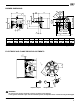
Specifications


3245
9
GB
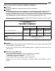
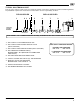
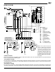
WIRING DIAGRAM
M
ST 1
ST 0
N4
ST 2
N3
N5
1 2 3 0 7 8 4 5 10 11
SM
P
8
5
1
11
B
12
15
16 17
96
RMG...
C
NC
NO
CN2
C
M
MV
14
SO
TA
CN1
TB
PA
2563 7 8 9 10 11 12
A
2
10
4
13
F
1
7
CN6
CN5
CN4
1
L
N
2563 7 8 9 10 11 124
Pc
VS
V1
PS
J
V2
GN D
T1
1
LN
2563 7 8 9 10 11 124
Pc
VS
V1
PS
V2
T1
GN D
T2
Wiring legend
C - Capacitor MV
F - Fuse 6.25A
CN... - Connectors
MV -Motor
PA - Air pressure switch
Pc - Valve source interlock
PS - Remote lock-out signal
SM - Servomotor
SO - Ionization probe
TA - Ignition transformer
TB - Burner earth
TR - Limit thermostat
TS - Safety thermostat
T2 -2
nd
stage thermostat
T6A -Fuse
V1 -1
st
stage gas valve
V2 -2
nd
stage gas valve
X12 - Terminal board 12 pole
TO BE DONE BY
THE INSTALLER
CARRIED-OUT
IN THE FACTORY
D7604
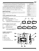
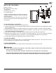
CONTROL CIRCUITS
Burner firing stage may be controlled by either a 120V or 24V control system. The required controls must be connected to the
burner as described on the following pages.
120V CONTROL SYSTEM
First stage firing is controlled by a 120V operating control wired between terminals 3 and 4 on the terminal block. To control
second stage fire on demand only, a second 120V control must be wired between terminals 7 and 8 after removing the fac-
tory-installed jumper.
24V CONTROL SYSTEM
First Stage firing is controlled by a 24V operating control wired between terminals 3 and 4 on the terminal block. To control second
stage fire on demand only, a second 24V control must be wired between terminals 7 and 8 after removing the factory installed jumper.
D7605
D7606
SINGLE STAGE BURNER - LOW FIRE START TWO STAGE BURNER FIRING
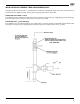
Note: If an external electrical
source is utilized, the conversion
burner, when installed, must be
electrically grounded with a solid
green wire to Earth Ground, in
accordance with local codes or, in
the absence of local codes, with
the National Electrical Code ANSI/
NFPA 70-1990 and the CSA Elec-
trical Code.