Service Manual REU-VR2632FFUD - 26i REU-VR2632 FFU-HD-E- HD50i Continuous Flow Water Heater Important. Read these instructions carefully before attempting installation or use of this appliance. All work must be carried out by competent persons.
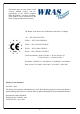
The Rinnai range of water heaters, when correctly installed, comply with the requirements of the United Kingdom Water Regulations / Byelaws (Scotland). These Products can be found listed in the Water Fittings and Materials Directory. The Rinnai water heaters are CE Marked as allowed by Technigas 26i - REU-VR2632FFUD-E HD50e - REU-VR2632WDHD-E HD50i - REU-VR2632FFUDHD-E HD70e - REU-VRM3237WHD-E HD70i - REU-VRM3237FFUHD-E Certificate numbers: E0841/5386 Rev.5 - E0716/5360 Rev.05 E1061/5498 Rev.
This manual is intended for use by Gas Safe Registered Engineers November 2012 3
CONTENTS CONTENTS……………………………………………………………………………..
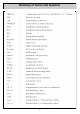
Glossary of Terms and Symbols 5
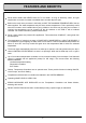
FEATURES AND BENEFITS Rinnai water heaters will NEVER RUN OUT of hot water. As long as electricity, water, and gas supplies are connected, hot water is available when hot water taps are open. Built into the main micro-processor is the facility to LIMIT THE MAXIMUM TEMPERATURE of the hot water supplied. The water temperature may be set to various temperatures. This is particularly useful when the hot water unit is installed where young children or the infirm may be using the hot water.
TECHNICAL DETAILS Model HD50e 26i - HD50i Installation External Internal G20 Nat Gas Press Low 1.29 1.75 mbar G20 Nat Gas Press High 6.81 9.35 mbar G31 Propane Press Low 2.21 2.36 mbar G31 Propane Press High 11.2 11.1 mbar Direct Forced Exhaust Forced, Room Sealed Flue System Units Temp. Range Controllers 37-46, 48, 50, 55, 60, 65, 75 °C Temp.
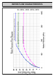
WATER FLOW CHARACTERISTICS 26i - HD50e - HD50i - HD70e - HD70i 8
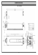
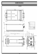
DIMENSIONS 26i - HD50i 9
DIMENSIONS HD50e 10
TEMPERATURE CONTROLS The purpose of a Temperature Controller is to enable the user to have localised control over the hot water supply. Used correctly, the hot water unit will supply hot water at the temperature selected, even when the water flow is varied, or when more than one tap is used. Adjustments to the operation of your hot water unit can be made with any of the Temperature Controllers. Each Temperature Controller can be individually programmed.
TEMPERATURE CONTROLS Remote temperature controllers provide control over the water temperature. Rinnai water heaters can be operated with 1, 2, 3, 4 or no temperature controllers. NOTE Each time a button is pressed, a BEEP will sound. The BEEP sound can be muted by depressing the Temperature Controller Up and Down buttons simultaneously for more than 3 seconds. This can be done for each Temperature Controller. To return to original settings, repeat this step.
TEMPERATURE CONTROLS Table A Models Information Given MC91 MC70 BC100 All Maintenance N/A ↓ + Power ↓ + Power Error History Power + ↑ ↑ + Power ↑ + Power Water Flow Rate ↑ + Power ________ ________ Outlet Water Temperature ↓ + Power ________ ________ Higher temperature Function Transfer + Power Held for 5 sec till noise N/A Turn off PIP Noise ↑ + ↓ Held for 5 sec till noise ↑ + ↓ Held for 5 sec till noise ↑ + ↓ Held for 5 sec till noise Table B Maintenance Monitor Section No.
TEMPERATURE CONTROLS Using the Temperature Controllers Adjusting Temperature Press the ON/OFF button on a temperature controller after making sure that water is not flowing. Simply press the Hot Water Temperature Up or Down arrow button The system will become active, the temperature will default to 40°C and the controller that turned the system on will have priority. HOTTER COOLER The temperature setting on the controller will light up.
TEMPERATURE CONTROLS Using 2 or more universal Temperature Controllers. Switching the system ON. The hot water system and all controllers can be switched ON and OFF from any controller by pressing the ON/OFF button as shown. When the system is turned ON the water temperature display will be lit. During normal operation the system is left ON. Do not push the ON/OFF button when water is running. Using hot water. Ensure the system is switched On by verifying the temperature display is lit.
TEMPERATURE CONTROLS Do not push the ON/OFF button on the Master controller after transferring priority of temperature selection to a Secondary controller as the system will shut down. Temperature priority cannot be switched to another controller when the water is flowing through the water heater.
TEMPERATURE CONTROLS General Information Commercial installations do not generally have controllers installed. These installations usually have one permanent set temperature that is constant at all times. The public should not have access to alter the temperature in these situations. These installations do not require controllers as the temperature can be set by a series of dip switches on the PCB. Exceptions to this are the following: 1.
OPERATION HD50e 26i - HD50i 18
MAIN COMPONENTS 1. Gas Control Unit 1.1 Modulating Valve This device is used by the PCB to adjust the volume of gas to the burner in proportion to the volumetric flow rate of water in order to maintain a supply of constant temperature hot water amid changes in water flow rates and incoming temperatures. 1.2 Change-over Solenoid Valves Additional solenoid valves are included to section the burner and stage the control in several steps.
WIRING DIAGRAM 26i - HD50e - HD50i 20
FLOW CHART 26i - HD50e - HD50i - HD70e - HD70i 21
DIP SWITCH SETTING Dip Switches Explained Dip Switch Positions Explained OFF ON SW1 1 2 3 4 5 6 7 8 - Model Choice Temperature Temperature Temperature Temperature Warm Water Switch Forced Combustion Forced Combustion OFF ON SW2 1 2 3 4 5 6 - Gas Type Gas Type Model Choice Model Choice Commercial Setting Not in use (OFF) FORCED COMBUSTION NORMAL OFF ON SW1 7 off 8 off GAS TYPE LPG OFF ON SW2 1 off 2 off LEGEND: Black Section indicates position of dip switch: OFF ON HD50e OFF ON SW1 1 on SW2 3 off 4
DIP SWITCH SETTING 26i - HD50e - HD50i - HD70e - HD70i Temperatures - with or without remotes connected OFF ON SW1 2 3 4 5 40°C OFF ON SW1 2 3 4 5 OFF ON SW1 2 3 4 5 42°C OFF ON SW1 2 3 4 5 55°C (Factory Setting for: 32e - 32i - 26e - 26i) OFF ON SW1 2 3 4 5 OFF ON SW1 2 3 4 5 60°C 50°C OFF ON SW1 2 3 4 5 65°C (Factory Setting for: 70e - 70i - 50e - 50i) NOTE: Bypass valve automatically closes if appliance is set at temperatures of 60°C or higher.
TESTING 1.Purge gas, hot water and cold water supply lines before making the final connection of the water heater. Swarf in either the gas or water supplies may cause damage. 2.Turn on gas and cold water supplies. 3.Test for water leaks and gas escapes near the unit. 4.Isolate gas and electric supply. Remove test point screw located on the inlet gas pipe work below the heater and attach pressure gauge. 5.Turn the power on at the switch and turn on gas.
GAS PRESSURE SETTING The working gas pressure on the water heater is electronically controlled and factory set. Under normal circumstances it does not require adjustment during installation. The pressure should be checked when the unit is installed and each time it is serviced to ensure that it is correct. Contact Rinnai before attempting to alter the gas pressure if you are unsure of what to do. Incorrect adjustment can void the warranty. 1. Turn 'OFF' the gas supply. 2. Turn 'OFF' 230V power supply.
GAS PRESSURE SETTING 10. Set the Rinnai to 'Forced Low' combustion by setting No.7 dip switch of SW1 to 'ON'. (Fig. 3) 11. Check the burner test point operating pressure. LOW GAS HD50e HD70e 26i HD70i HD50i NG G20 1.29 1.83 1.75 1.86 LPG G31 2.21 2.34 2.36 2.22 Fig. 3 (pressures in mbar) 12. Remove rubber access plug and adjust the regulator screw on the modulating valve (Fig. 4) as required to the pressure above. Replace rubber access plug and seal it shut. 13.
ERROR MESSAGES Troubleshooting without controllers If you have not installed temperature controllers and experience the following symptoms, please carry out the suggestions below. If symptoms continue, please contact Rinnai for advice. NOTE: Faults caused by insufficient gas/water supply or gas/water quality and installation errors are not covered by the manufacturer’s warranty. Fault Remedy Heater does not attempt Check the power is on at the heater. to start at all.
ERROR MESSAGES For extra assistance in Fault Diagnostics follow the FLOW CHART of page 21 Code Displayed Fault Remedy - Noticeable reduction in water flow Inlet water filter needs to be cleaned. 03 Power interruption during operation (water will not flow when power returned) Turn off all hot water taps and circulating pumps. Press ‘On/Off’ twice 10 Not enough combustion air Check for physical blockages around air intake or exhaust. Check combustion fan.
DIAGNOSTIC POINTS 29
Maintenance DRAWING A 30
Maintenance SERVICE PROCEDURE To carry out a full service on this appliance the following has to be carried out:1. 2. 3. 4. 5. 6. 7. 8. 9. 10. 11. 12. 13. 14. 15. 16.
Maintenance DRAWING B Manifold & Burner Box Removal 1. 2. 3. 4. 5.
Maintenance DRAWING C Gas Valve 1. 2. 3. 4. 5. 6.
Maintenance DRAWING D Fan Removal 1. 2. 3. 4. 5. 6. 7. 8.
Maintenance DRAWING D DRAWING E Filter , Flow / By Pass Servo`s and Flow Sensor 1. 2. 3. 4. 5. 6. 7.
Maintenance Drawing F 36
Maintenance Drawing G 37
Maintenance Drawing H 38
Maintenance To Remove Heat Exchanger As each item is removed keep the relevant screws with that item DRAWING F 1. 2. . Remove assembly `A` (see Manifold & Burner Box Removal page 39) Remove assembly `B` (see Fan Removal page 41) 1. Disconnect Heat Exchanger Pipes, undo screws `A` from plates `1` and spin plates out of the way and remove plates. Pull the 2 cold feed pipes `2` from out of the by pass servo Pull Hot feed pipe `3` from it`s housing.
LETTER OF COMPLIANCE 40
CE CERTIFICATE 41
CE CERTIFICATE 42
COMMISSIONING CHECK LIST 43
UK WARRANTY As the purchaser of this high quality Rinnai Water Heater you are provided with the following conditional warranty. Heat Exchanger All Other Parts Parts Labour Parts Labour Standard Use 3 Years 1 Year 3 Years 1 Year Commercial Use 5 Years 1 Year 5 Years 1 Year Rinnai 26i HD50e / HD70e HD50i / HD70i Definition of Standard Use. The warranty period allocated under Standard Use is based on Domestic and Light Commercial hot water usage.
UK WARRANTY WHAT IS COVERED? This Warranty covers any defects in materials or workmanship when the product is installed and operated according to Rinnai installation instructions, subject to the terms within this limited warranty document. This Warranty applies only to products that are installed by a registered gas engineer. Improper installation may void this Warranty.
CONTACT UK LTD. 9 Christleton Court Manor Park Runcorn Cheshire WA7 1ST Tel. 01928 531870 Fax. 01928 531880 E-mail. info@rinnaiuk.com Web. www.rinnaiuk.
RUK Tech Dept.