SERVICE MANUAL RCE-460PTR RCE-560PTR FAN CONVECTOR
Proudly a member of The Australian Gas Association. All of our products are AGA tested and approved. Distributed and serviced in Australia under a Quality System certified as complying with ISO 9002 by Quality Assurance Services. Rinnai New Zealand has been certified to ISO 9001 Quality Assurance by Telarc. Comparative Energy Consumption tested to The Australian Gas Association requirements of Australian Gas Code AG 103.
© Copyright Rinnai Australia Pty Ltd A.C.N. 005 138 769 All rights reserved Produced by Customer Technical Services February 2000 No portion or part of this manual may be copied without prior permission from Rinnai Australia. Rinnai Australia takes no responsibility for the accuracy or otherwise of information contained in this manual, and reserves the right to make modifications and change specifications without notice.
Table of Contents Glossary of Terms ..................................................................................................... v 1. Introduction .............................................................................................................. 1 2. Specifications ............................................................................................................ 2 3. Combustion Specification ......................................................................................
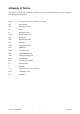
Glossary of Terms This glossary of terms and symbols is provided to assist you in understanding some of the language used throughout this manual.
1. Introduction Development Background Rinnai have developed a Portable Convector/Air Purifier Space Heater with an air purifying capacity that exceeds existing models and meets recent aims to improve health. We recommend that replaceable parts and the location of the unit be changed yearly. Features • Air Purifier 1. Removes cigarette smoke, pollen, household dust and other micro-particles. 2.
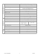
2. Specifications Model No. RCE - 460 PTR Name of appliance Portable Convector Output Main Unit Specifications Dimensions (mm) RCE - 560 PTR 5.5~18MJ/h (5.0 kW) Width 520 Depth 210 (base 305) Height 650 Weight (Kg) Connections 16.
Air Purifier Filter method (initial efficiency approx. 80%) Air Purifier Specification Anti-bacteria Activated Carbon (initial efficiency approx. 75%) Operation Operation Changeover Push button Automatic Operation (High/Med/Low) and Manual Operation (Boost/High/Med/Low) OFF Timer 3 step changeover (1, 2, 4 hour) Louvre Location Top of appliance Airflow (m3/min) Air Purifier Fan Boost 3.3, Hi 2.2, Med 1.8, Lo 1.
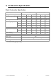
3. Combustion Specification Basic Combustion Specification Rinnai model reference RCE-460PTR Gas type Gas consumption (MJ/h) NG NG Propane LPG(NZ) 18 18 18 21 21 21 Low 5.5 6 6 5.5 6 6 φ 2.15 φ 1.40 φ 1.40 φ 2.15 φ 1.40 φ 1.40 A 1 1 1 1 1 1 B 0 0 0 0 0 0 *B 0 0 0 0 0 0 φ 20 φ 22 φ 22 φ 20 φ 22 φ 22 High 0.65 1.46 1.46 0.85 1.91 1.
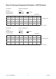
Warm Air Discharge Temperature Distribution - 560PTR (Heater) Conditions: Test gas: Measured Input: Nominal Input: Natural 20.90 MJ/h 21.00 MJ/h 4,990 kcal/h 5,020 (Unit ∆°C) 56 75 76 72 75 68 61 61 70 82 75 80 85 78 61 72 56 81 71 81 94 85 61 74 60 80 66 79 90 86 61 74 54 77 64 79 89 87 58 71 (Average 73.1) (Room temperature 26.0°C) Conditions: Test gas: Measured Input: Nominal Input: Natural 5.40 MJ/h 5.
Warm Air Discharge Velocity - 560PTR (Heater) (Unit m/sec) 2.91 2.91 3.31 3.99 3.46 2.79 2.76 1.88 3.39 3.52 3.67 4.31 4.13 3.34 3.12 1.64 3.53 3.94 4.29 4.29 4.30 3.77 3.61 2.58 3.87 4.40 4.19 4.23 4.76 4.09 3.48 3.16 4.34 4.28 3.83 4.96 4.61 4.60 3.40 3.45 (Average 3.68) (Unit m/sec) 1.54 1.72 1.87 2.68 1.67 1.49 1.86 1.17 2.22 2.41 2.39 2.62 1.98 1.84 2.35 1.08 2.12 2.64 2.60 3.14 2.77 2.50 2.41 1.63 1.68 1.95 2.37 3.10 3.
Warm Air Discharge Temperature Distribution - 460PTR (Heater) Conditions: Test gas: Measured Input: Nominal Input: Natural 18.10 MJ/h 18.00 MJ/h 4,320 kcal/h 4,300 (Unit ∆°C) 53 67 68 63 65 63 55 54 63 74 66 69 71 72 54 65 52 74 62 69 79 79 55 65 53 74 58 70 78 82 54 67 52 72 56 69 80 85 51 66 (Average 65.6) (Room temperature 26.0°C) Conditions: Test gas: Measured Input: Nominal Input: Natural 5.40 MJ/h 5.
Warm Air Discharge Velocity - 460PTR (Heater) (Unit m/sec) 2.58 2.58 2.93 3.53 3.07 2.47 2.44 1.66 3.00 3.12 3.25 3.81 3.66 2.96 2.76 1.45 3.13 3.49 3.80 3.80 3.80 3.34 3.20 2.29 3.43 3.89 3.71 3.74 4.22 3.62 3.08 2.80 3.84 3.79 3.39 4.39 4.08 4.08 3.01 3.06 (Average 3.26) (Unit m/sec) 1.54 1.72 1.87 2.68 1.67 1.49 1.86 1.17 2.22 2.41 2.39 2.62 1.98 1.84 2.35 1.08 2.12 2.64 2.60 3.14 2.77 2.50 2.41 1.63 1.68 1.95 2.37 3.10 3.
Air Discharge Velocity (Air Purifier) 460/560PTR (Unit m/sec) 1.42 1.57 1.27 1.24 2.43 3.73 2.76 1.56 2.73 4.05 4.73 4.13 4.80 4.20 4.90 3.41 4.62 5.30 (Avg 3.27) (Unit m/sec) 0.73 0.96 0.96 2.08 1.95 2.62 1.38 1.21 1.80 2.44 3.00 3.09 3.08 2.77 2.84 1.93 2.73 3.13 (Avg 2.15) (Unit m/sec) 0.57 0.78 0.82 1.88 1.50 1.99 1.57 1.03 1.38 1.85 2.53 2.71 2.72 2.25 2.37 1.77 2.29 2.63 (Avg 1.81) (Unit m/sec) 0.47 0.72 0.82 1.
Noise Level - 460/560PTR Heater Operation Noise (dB (A)) High: 41 Low: 27 Measuring method: According to Japanese Industry Standards During Combustion Air Purifier Operation Noise (dB (A)) Boost: 45 High: 35 Med: 31 Low: 27 Measuring method: According to JEM1467 Convector 460/560 PTR - 10 - ©Rinnai
4.
5. Installation The following clearances are recommended for installation.
6.
7.
8.
Normal Heater Operation • Press the Heat ON / OFF button. • The ON/Combustion indicator illuminates green, and the convection motor starts pre-purging. • The Digital Display displays the present room temperature. After approximately 3 seconds, the electrode starts discharging electricity, and at the same time, the solenoid valves and the modulating valve open.
• If the Heater button is pressed when the Timer is in stand-by mode or during combustion, the unit will go into normal OFF mode. Automatic-Economy Mode (Heater) 30 minutes after the present room temperature has reached the set room temperature, the Economy function will start operating automatically and the Economy indicator will illuminate.
Automatic Air Purifier Operation 1. Turning ON i) Press the “Air Purif” button. The Fan Speed “Auto” indicator will illuminate and the Air Purifier fan will rotate on High. The Dust Indicator will illuminate green. ii) After approximately 20 seconds, the fan speed will adjust automatically according to the cleanliness of the air. (The Air Purifier fan will operate at levels High, Med, and Low.) The 3 dust indicators will illuminate according to the degree of uncleanliness of the air in a room.
9. Main Componentry Safety Devices Incomplete Combustion Prevention The Incomplete Combustion Prevention Device senses flame temperature using a sensor with a thermocouple. Thermocouples are widely used as burner safety devices. The Incomplete Combustion Safety Device is incorporated in a special burner structure connected to an electronic sensor.
Sensor Specification Ignition Sensing Voltage (mV) ODS Sensing Voltage (mV) Output at initial check +2 NG: level 4~12 14 ± 1.5 level 1~3 14 ± 1.5 LPG: level 4~12 16 ± 1.5 level 1~3 16 ± 1.5 Thermocouple Output NG: >18mV LPG: >20mV <35mV NG: >18mV LPG: >20mV <35mV Drop Out Time (sec) Below 60 “Drop Out” = Time until the gas is cut off after flame failure. Sensing voltage varies depending on gas type.
Surge Protection Glass Fuse 3 Amp Valves Solenoid Valve Solenoid Valve 1 Single Seated Valve Solenoid Valve 2 Voltage DC90 V DC 90V Power Consumption Below 5 W Below 5 W Modulating Valve Voltage <200mA Consumption Below 1 W Convector 460/560PTR - 21 - ©Rinnai
Electrical Type Diameter (mm) Width (mm) Air flow Rate m3/min Fan (rpm) Convection Fan Line Flow Fan φ 110 328 (Full Combustion) High: 3.5(460PTR), 3.9(560PTR) Low: 2.5 High: 800 ± 70 (460PTR) 840 ± 70 (560PTR) Low: 550 ± 70 Air Purifier Fan Sirocco φ 160 80 Boost: 3.3 High: 2.2 Med: 1.8 Low: 1.4 Boost: 1100 ± 100 High: 740 ± 100 Med: 670 ± 100 Low: 600 ± 100 Note: Air flow rate is measured using a duct. Fan speed is measured using a finished product during air purifier operation.
Operating Principles 1. An air current is created by the heat generated from heater resistance guiding the surrounding unclean air into the area where the detector is. 2. The lens projects infra-red light around the detector. 3. When dust passes through the detector area, infra-red light is scattered, and the sections of scattered light are gathered with the lens into the Photo Tr. 4. The Photo TR converts scattered light into electrical signals.
Convector 460/560PTR - 24 - ©Rinnai
10. Operational Flow Chart Heater ON Cause eliminated Power Point ON No I 73 No II 71 Operation/Comb. Ind. flashes (red) Yes No ON/OFF SW. Normal 1 Power Point OFF Operation/Comb. Ind. flashes (red) Yes I: Micro-computer and E2PROM's signal path normal II: Solenoid valve and Modulation valve rotation normal III: Gas disconnection device normal when tilting C.M.: Convection Motor R.F.: Reverse Flame SV: Solenoid 70 Operation/Comb. Ind. flashes (red) Yes ON/OFF sw. ON A Operation/Comb. Ind.
Heater OFF TIMER ON/OFF Switch OFF ON/OFF switch ON Combustion A -> B Display Room Temp. 6Time Timer switch ON All Indicators OFF SV1 SV2 OFF Mod. valve OFF C.M. (med) ON Display Room Temp. 6Time C.M. OFF Operation/comb. Ind. illuminates (Green) (150~255 sec) SV1 SV2 OFF POV OFF C.M. (med) OFF Timer Ind. illuminates C.M.
11.
Memory Function for Maintenance Data The 5 most recent error messages and the estimated time of combustion, combustion frequency, estimated time of air purifier operation, and air purifier operation time are stored, as well as E2 PROM. While the unit is off, press the “override” and “∨” buttons simultaneously for at least 2.5 seconds to bring up the error history on the display. The error history will display the following in a 2.
E2 PROM data will not be erased during a power failure. However, this data is divided into 2 groups where one of the groups of data can be reset at the external control pads.
Normal OFF Test Button Low Pressure Mode e c on ton n t to Bu ut 1 B er st imes High Pressure Mode Te Tim n two t to t u B t Tes n 1 Butto Timer Test Mode Test Bu tton thr ee time s Te Timer 1 Butto Decision Level st n Bu Adjustment Mode Ti tto m n er 1 B fou rt ut im to es n Sensitivity Selection Mode The unit will go into Test Mode when the Test Switch is switched ON while the unit is operating.
1. During Gas Conversion Mode (left side of display) Gas Type NG LPG Gas Type Code 13 LP Displayed 2. During Test Mode The first and second digits of the LED display the level. The third and fourth digits of the LED display the entered data. The first and second digits will display: 5 second test delay Level 1 Level 12 ~ The third and fourth digits will display: for no entry for gas type for low pressure for high pressure for standard level 3.
5. Standard Level Mode 12mV High 14mV 16mV 18mV Low A function called “factory mode”* has been added to confirm appliance settings. *Displays set manufacturing values. 1. Operation Method Press the “∧” button continuously, then the “Heat” button. 2. Display Contents The set values for the Appliance Type Code, Gas Type Code, Flame Failure Detection Level, Dust Sensor Level will be displayed in that order at 2.5 second intervals. 3. Display Contents Information a.
An example of High Flame Failure Detection Level 12mV, and Low Flame Failure Detection Level 18mV d. Dust Sensor Level Level 1 Level 2 e. Afterwards, it will revert back to the normal temperature display.
Flow Chart CN No 1 Wire Colour No Measurement Value Part blue-blue switch OFF: 90~100k Ω ON: 10~30 k Ω Heater Switch <1 Ω Thermal Fuse B 16 G 2 17 white-white 38 G1 black-white 6 rpm (0.4Hz) DC 4~6V K white-white AC 90 ~110V K brown-brown DC 80~100V K1 brown brown 2.0~3.
O black-black AC 3~7V 31 ~43 Ω grey-black DC 4~6V 1.8~2.2k Ω 15 P grey-violet 16 C white-white Dust Sensor Dust indicator colour Voltage green-orange DC 0.8~2.2V orange-red DC 1.1~2.5V <1 Ω (ON) Micro-Switch Wire Colour No. Measurement Value grey - grey AC 207~264V 33~45 Ω white - white AC 90~110V 8~20 Ω blue - blue AC 8~12V 1~4 Ω brown - brown AC 8~12V 1~4 Ω violet - voilet AC 10~15V 0.5~2 Ω black - black AC 3~7V 0.
$ % % & ' ( Service Call System Check Points (No.’s refer to causes outlined in the following pages) Appliance does not operate after • Check electrical cord is connected to the power point. having pressed ON/OFF switch. • Confirm power supply. (ON/Combustion indicator does • Check Function Lock (Indicator). not illuminate green.) Ignition does not occur. (ON/Combustion Indicator does not illuminate red.
1. Gas Supply • Is the gas supply fully open? • Is the gas hose bent? • Is the gas supply squashed? • Is the gas hose too long? • Is the gas supply connected correctly? YEnsure the gas supply is fully open. YIgnition problems can be caused by poor gas supply, or air in the supply line. (There may be a gaseous odour until ignition.) 2.
10. Unclean Filter Cartridge • The replacement period for the filter cartridge will vary due to use and location of installation, however, it should be replaced yearly. ' % Condition Cause and Explanation Ignition is slow and cold air is When the ON/OFF switch is pressed, ignition occurs, however, blown from appliance ignition could be delayed due to air in the gas supply line.
) % * Note: Before carrying out resistance checks, disconnect power. *+ * ! ' , - .% + a. the convection fan does not begin to rotate. b. the solenoid valves do not open. c. there is no spark. Is there electrical supply? NO 1. Confirm the connection at the wall socket. YES Normal Value AC90~110V 2. Is the 3 amp fuse blown? Normal Value 0 Ω (125V/3A) a. The sequence does not continue. 1. 2. 3. 4. Broken wiring or loose pin connectors.
b. The convection fan does not begin to rotate. 1. Convection fan shaft grub screw loose. 2. An obstruction in the convection fan is preventing the fan from rotating. 3. Open circuit or bad connection in motor circuit. (Error code "62") Motor Coil Normal Value 150~300Ω 4. Faulty PCB. c. The solenoid valves do not open 1. Broken wiring or loose pin connectors. 2. Solenoid coil wiring is broken or shorted. SV1 SV2 Normal Value: 2.0~3.0kΩ Modulating Valve Normal Value 16~26Ω 3. Faulty PCB.
+ ' 1 0 ' 1 ' .% % 30 seconds after ignition, the spark stops and miss-ignition occurs. Miss-ignition No miss-ignition 1. Faulty indicator 2. Faulty PCB Confirm thermocouple output Thermocouple Output Checking Method (Connect the multimeter to the output checking terminal at the back of the appliance). Output Checking Terminal (Lower s, Upper ⊕) Is the output NG:14mV LP:16mV DC or above? NO YES 1.
+ ' % ! 1. Power failure. All indicators turned off. Heater ON/OFF Switch ON after power reinstatement. 2. Heater has been tilted. Tilt switch has activated. (Error code “03”). 3. A safety device has activated. • Air filter is blocked and OHS is activated. (Error code “14”) • Incomplete Combustion Prevention Device (ODS) is activated due to insufficient ventilation. • Kink/block in the gas supply hose. Hose too long. (Error code “12”) • Gas pressure is abnormally low.
+* ! ' * % - .% + a. the air purifier fan does not begin to rotate. Is there electrical supply? YES NO 1. Confirm the connection at the wall socket. Normal Value AC90~110V 2. Is the 3 amp fuse blown? Normal Value 0 Ω (125V.3A) a. The sequence does not continue. 1. 2. 3. 4. Broken wiring or loose pin connectors. (Open circuit) Faulty control panel PCB. (Air Purifier ON/OFF button) Faulty PCB. Loose primary filter. (Error code "05") b.
Confirming simple operation of dust sensor Necessary equipment Infra-red TV remote control 1. Remove the dust sensor cover on the right hand side of the appliance. (The dust sensor is inside the triangular opening.) 2. Press the air purifier button to turn it ON. The dust indicator will illuminate green. * If the power cord has just been plugged in, carry out this step after one minute has passed. 3.
4 5 1. Remove the front panel (see “Removal of the Front Panel Assembly” on page 48). 2. Remove the filter (see “Removal of the Purifier Filter” on page 48). 3. Replace small gas label on gas inlet, and large gas label on back of appliance. 4. Place new very small gas label on Data Plate. 5. Complete details on conversion sticker, place sticker inside front panel. 6.
6 5 % 7 % 1. Gas Type Changeover a. When the unit is off, press the test switch at the top of the PCB for at least 0.3 seconds; The unit will go into gas type changeover mode. The present gas type code will be shown on the left side of the display (NG(13), LP(LP), or Towns Gas(6C)). b. Choose the gas type code with the “∧”(Up) and “∨” (Down) buttons. c. The gas type code will be stored in memory when the test switch is pressed again.
8 7 127( e.g. - Isolate gas supply - Disconnect electrical supply from wall socket ITEM PAGE 1. Removal of the Purifier Filter . . . . . . . . . . . . . . . . . . . . . . . . . . . . . . . . . . . . . . . . . 48 2. Removal of the Control Panel Assy . . . . . . . . . . . . . . . . . . . . . . . . . . . . . . . . . . . . . 48 3. Removal of the Front Panel . . . . . . . . . .
1. Removal of the Purifier Filter 3. Removal of the Front Panel CAUTION 240 Volt exposure. Isolate the electrical supply to the appliance and reconfirm with the neon screwdriver or multimeter. CAUTION 240 Volt exposure. Isolate the electrical supply to the appliance and reconfirm with the neon screwdriver or multimeter. a. Remove three (3) bottom screws (1 on each side, 1 at front). a. Remove the thumb screw (1 screw). b. Remove the Primary Filter, then the Purifier b. Follow sections 2. a. and b.
d. Remove the eight (8) screws securing the fan c. Disconnect 3 connectors (main PCB, surge housing to the back panel. protector and dust sensor. Follow section 6 to remove dust sensor.) d. Disengage transformer. 6. Removal of the Dust Sensor CAUTION 240 Volt exposure. Isolate the electrical supply to the appliance and reconfirm with the neon screwdriver or multimeter. e. Remove the capacitor to the right of the fan housing (1 screw) and wiring loom from the main PCB. a.
7. Removal of the Surge Protector and Sparker Unit c. Remove the two (2) screws from the OHS. CAUTION 240 Volt exposure. Isolate the electrical supply to the appliance and reconfirm with the neon screwdriver or multimeter. a. Follow section 3 (Removal of the Front Panel). 9. Removal of the Thermocouple b. Remove two (2) screws from the surge protector sparker unit bracket. CAUTION 240 Volt exposure. Isolate the electrical supply to the appliance and reconfirm with the neon screwdriver or multimeter. a.
d. Disconnect connector from PCB. b. Disconnect the gas supply hose at the rear of the appliance. e. Remove the two (2) screws securing the bracket and disengage from burner assy (top c. Remove one (1) screw from the front of the gas supply tube upper to remove. and bottom). Note: Don’t lose O-rings from gas tube. d. Remove two (2) screws from front of the gas supply tube lower. f. Remove one (1) screw to release the thermocouple from the bracket (side). e. Remove gas tube. 10.
13.Removal of the Convection Fan Assy 14.Removal of the Combustion Chamber CAUTION 240 Volt exposure. Isolate the electrical supply to the appliance and reconfirm with the neon screwdriver or multimeter. CAUTION 240 Volt exposure. Isolate the electrical supply to the appliance and reconfirm with the neon screwdriver or multimeter. a. Follow section 3 (Removal of the Front Panel). a. Follow section 3 (Removal of the Front Panel). b. Follow section 7 c (Removal of the Surge Protector and Sparker Unit).
15.Removal of the Spark Electrode f. Lift and remove locating bracket. CAUTION 240 Volt exposure. Isolate the electrical supply to the appliance and reconfirm with the neon screwdriver or multimeter. g. Remove one (1) screw from the other end of the combustion chamber (middle). h. Remove thermocouple assy (follow section 9). a. Follow section 3 (Removal of the Front Panel). b. Follow section 14 (Removal of the Combustion Chamber.) c. Remove two (2) screws to remove the electrode bracket. i.
17. Removal of the Thermistor a. Follow section 3 (Removal of the Front Panel). b. Pry open the two (2) locating clips with a screwdriver and disconnect from the PCB. 18.Removal of the Injector a. Follow section 3 (Removal of the Front Panel). b. Remove four (4) screws (2 from bracket, 2 from injector block). c. Remove one (1) screw from gas tube upper. d. Disengage the gas supply tube (top and bottom). e. Remove the injector block and pull the injector free.
9 : Legend bl: blue bk: black Convector 460/560PTR r: red gy: grey w: white or: orange - 55 - y: yellow br: brown v: violet gr: green ©Rinnai
; / ( Convector 460/560PTR - 56 - ©Rinnai
# ' Convector 460/560PTR - 57 - ©Rinnai
Convector 460/560PTR - 58 - ©Rinnai
Convector 460/560PTR - 59 - ©Rinnai
Convector 460/560PTR - 60 - ©Rinnai
Convector 460/560PTR - 61 - ©Rinnai
Convector 460/560PTR - 62 - ©Rinnai
Convector 460/560PTR - 63 - ©Rinnai
Convector 460/560PTR - 64 - ©Rinnai
Convector 460/560PTR - 65 - ©Rinnai
7 & - * &- 7 AUSTRALIA PTY. LTD. A.C.N.