Owner’s Operation and Installation Manual for the RHFE-750ETRA Direct Vent Fireplace Table of Contents........... 2 Safety Information .......... 2 Operating Instructions .... 6 Care and Maintenance ... 11 Fault Codes.................... 14 Installation Instructions .. 15 Consumer Support ......... 38 INSTALLER: Leave this manual with the appliance. CONSUMER: Retain this manual for future reference.
This appliance may be installed in an aftermarket, permanently located, manufactured home (USA only) or mobile home, where not prohibited by local codes. This appliance is only for use with the type of gas indicated on the rating plate. This appliance is not convertible for use with other gases, unless a certified kit is used. Table of Contents Consumer Safety Information Safety Definitions ........................................ 2 Safety Behaviors and Practices.................. 3 Safety Features .......
Safety Behavior and Practices WARNING • Keep the area around the appliance clear and free from combustible materials, gasoline, and other flammable vapors and liquids. • Do not use this appliance if any part has been under water. Immediately call a qualified service technician to inspect the appliance and to replace any part of the control system and any gas control which has been under water. • Do not operate appliance with the glass front removed, cracked, or broken.
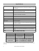
Specifications Application Vented gas fireplace heater; Inbuilt only; for residential installation, commercial setting, or manufactured home; not designed for installation in a solid-fuel burning fireplace Certification CSA certified according to ANSI Z21.88, CSA 2.
Features • Direct Vent: Intake air is taken from the outside and the combustion products are exhausted to the outside. Therefore the furnace has no effect on the quality of the indoor air. • Pre-heat: The appliance will turn on before the programmed ON time and begin raising the room temperature to that of the programmed temperature by the ON time. • Push Button Ignition: Only one push of the STANDBY/ON switch is all that is required to operate the heater.
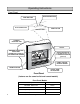
Operating Instructions Front Panel OPERATION INDICATOR TIMER INDICATOR FAULT CODE DISPLAY ON/OFF BUTTON CONTROL PANEL OVERHEAT DISCHARGE VENT LOG SET TEMPERED GLASS IN THE FRONT PANEL CERAMIC GLASS PANEL AT THE COMBUSTION CHAMBER BLOCKAGE INDICATOR for FILTERS (flashes red) for WARM AIR DISCHARGE (glows red) REMOTE CONTROL RECEIVER WINDOW ROOM AIR RETURN LOUVER, WARM AIR DISCHARGE Front Panel (features are the same for flat and curved models) Front Panel Models 6 Description Part Number Flat Meta
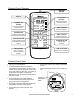
Remote Control Features INFRARED EMITTER DISPLAY Lock OverrideAuto Off Flame AM PM Temperature Time Clock Set Timer 1 Set ON OFF Timer 2Set ON OFF STANDBY / ON BUTTON Stops and operates the heater remotely STANDBY ON FLAME BUTTON Controls the flame level UP and DOWN BUTTONS Changes temperature, flame level, or time TIMER 1 BUTTON Sets timer program 1 Timer 1 TIMER 2 BUTTON Flame Timer 2 Sets timer program 2 Auto Off Override OVERRIDE BUTTON Lock Time Set AUTO AUTO OFFOFF BUTTON Turns the fl
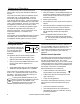
Sequence of Operations The combustion fan will run for several seconds before ignition to purge the combustion chamber of any gas. If the front burner fails to ignite the appliance will turn off and fault code 11 will be displayed. If the rear burner fails to ignite the appliance will turn off and make another attempt to ignite. If this second attempt fails, the appliance will automatically turn off and fault code 11 will be displayed.
Basic Fireplace Operations Adjusting the Temperature Flame Function Pressing the UP and DOWN buttons will change the temperature setting by 2 degree (F) increments. The display will show “Temperature” and the new temperature as confirmation.
Timers Programming the clock and timers The clock must be set before the timers will operate. The temperature setting during timer operation is the temperature last used when the appliance was on. During the steps below, if no button is pressed for 90 seconds then the screen will return to the current time display. Time Set 1. Press the TIME SET button. The display will show the words “Clock Set” and “AM 12:00” or the time. go into standby mode and the Timer Indicator will glow green.
Care and Maintenance Maintenance Repairs should be performed by a qualified service technician. The appliance should be inspected annually by a qualified service agency. More frequent cleaning may be required due to excessive lint from carpeting, bedding material, etc. It is imperative that control compartments, burners, and circulating air passage ways of the appliance be kept clean.
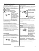
Care and Maintenance The pilot flame should be blue and extend over the flame rod from half to three-fourths of its length. It should not be long, streaky, or yellow. 2. Remove two screws attaching the front panel to the appliance. CORRECT PILOT FLAME APPEARANCE 3. Remove the front panel by rotating the bottom away from the appliance and lifting upwards to unhook the panel from the top of the appliance.
Troubleshooting Problem Possible Solutions or Explanation No display on remote Replace the remote control batteries. No ignition or no panel indications Ensure the appliance has power. Press the control panel ON/OFF button. Burners fail to ignite Air may need to be purged from the gas line. Several ignition attempts may purge the gas line. Turn on the gas supply. Combustion stops during operation Remove any obstructions from the louvers. Turn on the gas supply.
Fault Codes If there is a malfunction the appliance may shut down as a safety precaution and display a fault code to assist in diagnosing the problem. The fault code will flash in the Fault Code Display window and the Operation Indicator will flash green. Code Fault Remedy 11 Ignition failure Confirm that the gas supply is turned on. Switch appliance to STANDBY and then ON again. If ignition failure continues then a Service call is required.
Installation Instructions General Instructions The appliance must not be connected to a chimney flue serving a separate solid-fuel burning appliance. WARNING Do not use substitute materials. Use only parts certified with the appliance. A qualified service technician should install the appliance and inspect it before use. The installation must conform with local codes or, in the absence of local codes, with the National Fuel Gas Code, ANSI Z223.
Clearances to Combustibles The clearances to combustibles as stated on the rating plate and as shown in the figures must be followed. Also refer to the Safety Behaviors and Practices section.
Flue Terminal Clearances Ref Description Canadian Installations US Installations A Clearance above grade, veranda, porch, deck, or balcony. (Take into account the anticipated snow line.
Location This appliance has a cool outer casing that allows it to be installed in a recessed application consisting of combustible materials such as wood and plaster. The location needs to have a level surface that allows the appliance to be rolled in or out of the enclosure. If the surface is elevated and there is not enough room for it to be rolled out then a base and joists may be used as shown. The appliance will have to be rolled out for maintenance.
Location Wall Lining Use the adjustment feet so that the appliance is level and not tilted. They are initially installed immediately behind the side louvers but can be moved forward for better access in hearth or floor installations. The hearth should not block the appliance from being rolled out nor should it prevent the front panel from being installed or removed. Correct Floor Level Installation Adjustment feet Floor (Timber, Concrete, Tile, etc.
Venting There are 2 categories for venting: I. Venting with Flue Manifolds FOT-203 or FOT-204 - horizontal venting directly through the wall with no extensions. II. Extended Venting - horizontal and vertical terminations with a maximum 33 feet and 3 elbows. I. Venting with Flue Manifolds FOT-203 and FOT-204 The following flue manifold sizes are available: Name Kit No.
Venting 2. Assemble and Adjust the Sleeve Length Measure wall thickness through previously drilled 3 1/2 inch (90 mm) hole. The end of the sleeve should protrude 3/16 - 3/8 inch (5-10 mm) from the outside wall. In the FOT-203 (Vent Kit A) there are 4 parts provided with which to assemble the sleeve. Use the table to determine which pieces to assemble. In both kits, two parts are threaded for additional adjustment. Adjust the sleeve length to wall thickness plus 3/16 - 3/8 inch (5-10 mm).
Venting 5. Lock the ties Locking ties Pulling hard on the left and right hand ties, clip the ties over the notches inside the sleeve. You should be able to pull the ties 2 or 3 notches past the starting point. Cut the ties, leaving about 3/4 inch (20 mm) past the notch. Bend the ties back into the sleeve and parallel to the wall. Sleeve 6. Attach Inside Connection Assembly Push the assembly into the terminal tube. Attach the inside connection with 3 screws.
Venting Certified and Listed Vent Products Maximum Length = 33 feet (10 m) and 3 elbows Manufacturer: Metal-Fab Product: Corr/Guard Part Number Description 3CGRFA Adapter 3CGDS Condensate Collector 3CGRVT Vertical Termination 3CGRHT Horizontal Termination 3CG6 6” Vent Pipe Extension 3CG12 12” Vent Pipe Extension 3CG18 18” Vent Pipe Extension 3CG24 24” Vent Pipe Extension 3CG36 36” Vent Pipe Extension 3CGRHA 90 Degree Vent Pipe Elbow VERTICAL TERMINATION, 3CGRVT VENT PIPE EXTENSION C
Venting Additional Venting Clearances The top of the vertical termination should not be less than 18 inches from the storm collar. Refer to the instructions of the vent system manufacturer for complete component assembly instructions. Horizontal Vent Termination Wall The distance between the wall and the air inlet cover should be 1.0 - 2.36 inches (25 - 60 mm) Vent Length Switch If using extended venting, move the dip switch in the control panel to L-F.
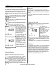
Connections 1. Carefully remove the packaged ceramic logs and place in a safe location. 2. To ensure the correct positioning, terminate the gas supply so that it is 5.9 inches (150 mm) from the front of the enclosure. 6. Unscrew the flue access panel held by two screws located inside the top left hand corner of the appliance. Slide this panel to the right behind the convection fan. 3.
Connections 9. Remove clamp L and slide the vertical pipe M down into the lower elbow N to remove parts J and K. Separate J and K. J 13. Slide tube M up into elbow K and clamp together with clamp L. K L 14. Slide the flue access panel back into position and attach with two screws. This panel may be turned upside down to allow for a different flue pipe height. 15. Open both of the air return louvers on both sides. Secure the appliance using the four mounting points. M 4 mounting points N 10.
Final Assembly Install the Logs The log set consists of seven pieces as follows: • rear • right hand top • left hand middle • left hand front • right hand middle • right hand front rear Step 3 • center top 1. Remove the two retaining screws that secure the combustion chamber glass panel. 2. Rotate and lift the combustion chamber glass clear of the combustion chamber and place in a safe location.
Final Assembly Ensure that the sealing material completely covers the perimeter of the glass. Squeeze the sealing material so that it is no longer flat. This will allow it to flatten correctly when installed. Correct WARNING Installing Glass Panel Ensure that the lower slots are properly positioned against the combustion chamber. The slot should be between the tapered washer and the appliance; it should not be between the tapered washer and the spring.
Final Assembly Air Guide Vanes Install the Front Panel To move the air flow more to the right or to the left, bend the air guide vanes using only light hand pressure. 1. Install the front panel by hooking the top into the body and rotating the bottom towards the appliance. Hook top first Do not bend repeatedly (no more than 5 times) or else the vane will break. Front Panel then rotate inward 2.
Operating Instructions FOR YOUR SAFETY READ BEFORE OPERATING WARNING If you do not follow these instructions exactly, a fire or explosion may result causing property damage, personal injury or loss of life. A. This appliance is equipped with an ignition device that automatically lights the pilot. Do not try to light the burner by hand. B. BEFORE OPERATING smell all around the appliance area for gas. Be sure to smell next to the floor because some gas is heavier than air and will settle on the floor.
Wiring and Schematic Diagrams CAUTION Label all wires prior to disconnection when servicing controls. Wiring errors can cause improper and dangerous operation. If any of the original wire as supplied with the appliance must be replaced, it must be replaced with type 18 AWG wire or its equivalent.
Parts List For replacement parts call Rinnai at 1-800-621-9419.
Parts List Rinnai Corporation RHFE-750ETRA 33
Parts List 131 120 100 104 105 119 103 132 118 80 117 101 134 106 97 124 108 125 107 98 99 110 122 116 126 49 114 99 98 101 113 128 111 115 121 112 109 127 123 133 118 74 115 129 123 102 120 117 34 Rinnai Corporation RHFE-750ETRA 123 130
Parts List ITEM 1 2 3 4 5 6 7 8 9 10 11 12 13 14 15 16 17 18 19 20 21 22 23 24 25 26 27 28 29 30 31 32 33 34 35 36 37 38 39 40 41 42 43 44 44 45 45 46 47 47 QTY 1 2 1 1 2 2 2 1 1 1 1 2 2 1 1 1 1 1 1 1 1 1 1 1 1 1 1 1 1 PART NO.
Parts List ITEM 48 48 48 49 QTY 2 1 1 1 PART NO. 10359F 10359B 10359G 10764 DESCRIPTION BURNER ASSEMBLY BRAY 250 Ø3.0 x 2 BURNER ASSEMBLY BRAY 250 Ø6.0 x 2 BURNER ASSEMBLY BRAY 250 Ø6.
Parts List ITEM 90 91 92 93 94 95 96 97 98 99 100 101 102 103 104 105 106 107 108 109 110 111 112 113 114 115 116 117 118 119 120 121 122 123 124 125 126 127 128 129 130 131 132 133 QTY 1 1 1 1 1 1 1 1 1 1 1 1 1 1 1 1 1 1 1 1 1 1 1 2 2 1 1 1 1 1 1 1 1 1 1 1 1 PART NO.
Consumer Support Warranty Information The installer is responsible for your heater’s correct installation. Please complete the information below to keep for your records: Purchased from: ___________________________________________________________ Address: _____________________________ Phone: ___________________________ _____________________________ Date of Purchase: __________________________________ Model No.: ________________________________________ Serial No.
Limited Warranty - continued What will Rinnai do? Rinnai will repair any part or component that is defective in materials or workmanship as set forth as follows. All repair parts must be genuine Rinnai parts. All repairs or replacements must be performed by an individual or servicing company that has been authorized by Rinnai. Replacement of the product may be authorized by Rinnai only.
Manufactured by Rinnai New Zealand LTD 105 Pavilion Drive, Airport Oaks Mangerg, Manukau City New Zealand 15237 (Issue G)