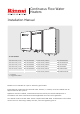
Continuous Flow Water Heaters Installation Manual To suit models: Rinnai Infinity VT16 REU-VR1620WG Rinnai Infinity HD200 REU-VRM2632WC Rinnai Infinity VT20 REU-VR2024WG Rinnai Infinity HDi200 REU-VR2632FFUG Rinnai Infinity VT24 REU-VR2426WG Rinnai Infinity HD250 REU-VR3237WG Rinnai Infinity VT26 REU-VR2626WG Rinnai Infinity EF24 REU-K2430WG Rinnai Infinity VTa26 REU-VR2626WGT Rinnai Infinity EF250 REU-KM3237WD Rinnai Infinity EFi250 REU-KM3237FFUD i = internal a = aggressive water M
Contents Before installation 3 Applicable models 3 Appliance location 4 General installation information 6 Connections and fittings 8 Dimensions - VT and HD range 9 Dimensions - EF range 10 EF250 models: Earthing the unit 11 Condensate Drain - EF models only 12 Controllers - general 14 Controllers - Universal installation 16 Controllers - Kitchen Deluxe installation 17 Controllers - Bathroom Deluxe installation 18 Controllers - communication cables 19 Commissioning 21 Recommend
Before installation Unpack appliance and flue components (if applicable) and check for damage. DO NOT install any damaged items. Check all components have been supplied and that you have the correct gas type. Read these instructions to get an overview of the steps required before starting the installation. Failure to follow these instructions could cause a malfunction of the appliance. This could result in serious injury and property damage.
Appliance location Installation in environments free from corrosive compounds Air surrounding the water heater, venting and vent termination(s) is used for combustion and must be free from compounds that cause corrosion of internal components. These include corrosive compounds that are found in aerosol sprays, detergents, bleaches, cleaning solvents, oil based paints/varnishes, and refrigerants. Therefore Rinnai recommends outdoor models be used for these locations where possible.
Appliance location External models External models are designed for outdoor installations only. They must be located in an above ground open-air situation with natural ventilation, without stagnant areas, and where gas leakage and products of combustion are rapidly dispersed by wind and natural convection. They must be mounted on a vertical structure with the water and gas connections on the underside pointing downwards.
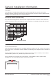
General installation information Catch pan It is important a suitably drained catch pan is fitted (especially for internal units) where damage could be caused by discharge from the water heater. Provision must be made for safe disposal of any leaking water to an external location. Flued water heaters (internal units) The chart below highlights the maximum flue length and number of bends. It also shows the difference between a short and long flue—this is important if changing settings (dip switches).
General installation information Pipe sizing Refer ‘Connections and Fittings’ for appliance gas consumption. If the gas pipe sizing is insufficient the customer will not get the full performance benefit. Gas pipe sizing must consider the gas input to this appliance as well as all the other gas appliances in the premises. The gas meter and regulator must be specified for this gas rate. An approved sizing chart such as the one in NZS 5261 should be used.
Connections and fittings Models Gas Consumption MJ/h Water Supply kPa Min. Weight kg Max.
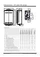
Dimensions - VT and HD range A B I G J H C F D L K E M A Width 350 350 350 350 350 (REU-VR3237WG) (REU-VR2632FFUG) HD250 Ext HDi200 Int (REU-VRM2632WC) HD200 Ext (REU-VR2626WGT) VTa26 Ext (REU-VR2626WG) VT26 Ext (REU-VR2426WG) VT24 Ext (REU-VR2020WG) VT20 Ext VT16 Ext (REU-VR1620WG) Dimension (mm) 350 350 470 B Depth 194 194 194 194 194 250 235~275 244 C Height - Unit 530 530 530 530 530 600 600 600 D Height - Including Brackets 571 571 571 571
Dimensions - EF range A B I G H C J F D L K E M Dimension (mm) EF24 Ext (REU-K2430WG) EF250 Ext (REU-KM3237WD EFi250 Int (REU-KM3237FFUD) A Width 350 470 470 B Depth 277 283.1 257~307 C Height - Unit 600 654 654 D Height - Including Brackets 644 721.6 721.6 E Hot Water Outlet (from wall) 164.5 100 100~150 F Hot Water Outlet (from centre) 100 100 100 G Cold Water Inlet (from wall) 83 64.6 64.6~114.6 H Cold Water Inlet (from centre) 53* 27.2 27.
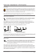
EF250 models: Earthing the unit Removing the cover and earthing the unit For the Rinnai condensing continuous flow water heaters (EF250 & EFi250), the earthing screws are located under the side trim, refer image below. First remove the trim and then the earthing screws before lifting off the cover. For safe operation of the appliance the earthing screws MUST be replaced. WARNING Earthing screws located under side trim Rinnai New Zealand Ltd.
Condensate drain - EF models only The Rinnai Infinity EF water heaters generate condensate continuously at a rate of up to five litres per hour as a by-product of a highly efficient gas burner. Condensate must be drained via a pipe to a suitable discharge point. As condensate is a by-product of gas combustion it is mildly acidic. For this reason copper tube and fittings MUST NOT be used as it will corrode. Instead Rinnai recommend plastic pipes and fittings.
Condensate drain - EF models only Installation of a condensate drain Point of discharge from each drain line shall be located so the release of condensate does not cause a nuisance, is readily discernible and incurs no risk of building damage. There shall be no tap, valve or other restrictions in any line. Each line shall fall continuously from the valve to the approved point of discharge. Drain lines shall not discharge into a storage water heater safe tray.
Controllers - general Water controllers are available as an optional extra. Universal (Compact), Deluxe and Wireless Controllers can be used together. A maximum of four water controllers can be fitted with the following limitations: • Maximum of one Kitchen Deluxe Controller (MC-100V) • Maximum of two Bathroom Deluxe Controllers (BC-100V) • Only one controller can be set to deliver 55 °C, this cannot be a Bathroom Deluxe Controller This section refers to wired controllers.
Controllers - general Positioning Controllers must be installed in shaded and clean locations. They should be fitted out of reach of children (suggested height 1.5 m). The Compact and Bathroom Deluxe Controllers are water resistant, however, durability is improved when positioned outside the shower recess or at least 400 mm above the highest part of a sink, basin or bath. Water controller cables Water controllers operate at extra low voltage (12 Volts DC) which is supplied from the water heater.
Controllers - Universal installation Fitting the Universal (Compact) Controller 1. Determine the most suitable position for the controller. 2. Drill three holes as shown (Fig.1 and Fig.2) for the securing screws and one to provide cable access. 3. When running cable through the access hole ensure the connector end of the cable is located nearest to the controller (Fig.2). 4. Carefully remove the face plate from the controller using a screwdriver (Fig.3). 5.
Controllers - Kitchen Deluxe installation 1. Determine the most suitable position for the controller. 2. Use the wall mounting bracket as a template to mark and drill three holes, locating the cable access hole as shown below. 3. Fix the mounting bracket to the wall using the appropriate fixings. 4. Run the water controller cable through the hole in the wall. 5. Carefully remove face plate from the controller, using a screwdriver as shown below. 6.
Controllers - Bathroom Deluxe installation 1. Determine the most suitable position for the controller. 2. Mark and drill three holes, locating the cable access hole as shown (Fig.1). 3. When running a cable through the access hole ensure the connector end of the cable is located nearest to the controller (Fig.2). 4. Affix the double sided self-adhesive seal to the back of the controller (Fig.3). 5. Carefully remove the face plate from the controller.
Controllers - communication cables Communication cables connect the water heater to the water controllers and operate at an extra low voltage (12 Volts DC) which is supplied from the water heater. Communication cables are supplied with the water controllers (15 m) and are fitted with spade terminals for connection to the water heater. Up to two cables can be connected to the cable connector at the water heater. Extension cables are available from Rinnai.
Controllers - communication cables Connecting three to four controllers 1. Repeat steps 1-3 on previous page. 2. To connect three to four controllers, separate all the cables to be fitted into pairs. Cut off the existing spade connectors from each pair and re-terminate each pair into a new spade connector (F) (available from your local electrical supplier) so there are only two sets of spade connectors. Four spade connectors in total to be terminated. 3. Repeat steps 4 and 5 on previous page.
Commissioning Testing 1. Ensure building occupants do not have access to the hot water outlets during this procedure. WARNING 1. Before final connection of the water heater, purge the gas and hot and cold water supply lines. Swarf in the gas or water supplies may cause damage. 2. Turn on the gas and water supplies and test for leaks (gas and water) near the unit. 3. Isolate gas supply. Remove test point screw located on the gas inlet and attach pressure gauge. 4.
Recommended solar system layout Warning about hot water Rinnai continuous flow water heaters configured for solar systems produce hot water at 75 °C and are not suitable for use with water controllers. The household water supply MUST be protected by a suitable tempering valve. Installation Rinnai continuous flow water heaters in solar installations are only suitable as gas boosters in solar hot water systems.
Dip switch settings - important Dip switch settings must only be changed by a licensed gasfitter. They have been provided as there may be a requirement to change the temperature of the water delivered from the water heater. WARNING Care must be taken when changing the temperature settings as the dip switches are small and can be easily switched or bumped into the wrong position.
On Dip switch settings Off Applicable models and REU-numbers Rinnai Rinnai Rinnai Rinnai Rinnai Rinnai Infinity Infinity Infinity Infinity Infinity Infinity VT16 VT20 VT24 VT26 VTa26 EF24 External External External External External External REU-VR1620WG REU-VR2024WG REU-VR2426WG REU-VR2626WG REU-VR2626WGT REU-K2430WG Dip Switch 1: Upper SW(8P) SW No.
On Dip switch settings Off Applicable models and REU-numbers Rinnai Infinity HD200 Rinnai Infinity HDi200 Rinnai Infinity HD250 External Internal External REU-VRM2632WC REU-VR2632FFUG REU-VR3237WG Dip Switch 1: Upper SW(8P) SW No. 1 Note FF model Flue setting Off W model Model setting Off Long flue (p. 6) On Short flue (p.
On Dip switch settings Off Applicable models and REU-numbers Rinnai Infinity EF250 Rinnai Infinity EFi250 External Internal REU-KM3237WD REU-KM3237FFUD Dip Switch 1: Upper SW(8P) SW No. Note 1 Flue settings Off EF250 Ext & EFi250 Int long flue (p. 6) On EFi250 Internal short flue (p.
Consumers: Installers: 0800 RINNAI (746 624) 0800 TO RINNAI (86 746 624) Address: 105 Pavilion Drive, Airport Oaks, Mangere, Manukau PO Box 53177, Auckland Airport, Manukau 2150 Phone: Fax: (09) 257 3800 (09) 257 3899 Email: Website: info@rinnai.co.nz www.rinnai.co.nz All Rinnai appliances meet or exceed the safety standards required by New Zealand gas and electrical regulations.