
Installation manual


Rinnai New Zealand Ltd. Continuous Flow Water Heater Installation Manual:
03-11
8
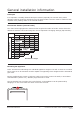
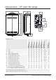
Connections and ttings
Models Gas Consumption
MJ/h
Water
Supply kPa
Weight
kg
Fittings Condensate
Min. Max. Hot Cold Gas
VT16 Ext
REU-VR1620WG
125 120 1000 15
R½
(15 mm)
R½
(15 mm)
R¾
(20 mm)
VT20 Ext
REU-VR2024WG
160 160 1000 16
R¾
(20 mm)
R¾
(20 mm)
R¾
(20 mm)
VT24 Ext
REU-VR2426WG
188 180 1000 17
R¾
(20 mm)
R¾
(20 mm)
R¾
(20 mm)
VT26 Ext
REU-VR2626WG
199 180 1000 17
R¾
(20 mm)
R¾
(20 mm)
R¾
(20 mm)
VTa26
REU-VR2626WGT
199 180 1000 17
R¾
(20 mm)
R¾
(20 mm)
R¾
(20 mm)
HD200 Ext
REU-VRM2632WC
199 140 1000 21
R¾
(20 mm)
R¾
(20 mm)
R¾
(20 mm)
HDi200 Int
REU-VR2632FFUG
195 140 1000 21
R¾
(20 mm)
R¾
(20 mm)
R¾
(20 mm)
HD250 Ext
REU-VR3237WG
250 200 1000 29
R¾
(20 mm)
R¾
(20 mm)
R¾
(20 mm)
EF24 Ext
REU-K2430WG
162 240 1000 27
R¾
(20 mm)
R¾
(20 mm)
R¾
(20 mm)
R½
(15 mm)
EF250 Ext
REU-KM3237WD
211 240 1000 32
R¾
(20 mm)
R¾
(20 mm)
R¾
(20 mm)
R½
(15 mm)
EFi250 Int
REU-KM3237FFUD
211 240 1000 32
R¾
(20 mm)
R¾
(20 mm)
R¾
(20 mm)
R½
(15 mm)
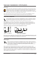
Service connection points
These dimensions are NOT an indication of the pipe sizes required.
An approved full ow isolation valve and disconnection union MUST be tted to the cold water
inlet. A non-return valve is not required unless required by local regulations.
Isolation valves must be tted so the appliance can be removed.
Purge gas and cold water supply lines to remove air and swarf before nal connection of the
appliance. Swarf in the gas or water supplies may cause damage.