Boiler Applications Drawings 800000026 Rev A 06//2010
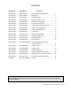
Contents Drawing No. Boiler Model Description EPD-09-0001 ............E Series Boiler ............ DHW Piping Thermostatic Valve ..................... 3 EPA-09-0001 ............E Series Boiler ........... Single Zone...................................................... 4 QPD-09-0001 ...........Q175C Boiler .............. DHW Recirculation .......................................... 5 QPD-09-0002 ...........Q Series Boiler ........... DHW from Indirect Tank ..................................
Boiler Applications Manual 800000026 Rev A
Boiler Applications Manual 800000026 Rev A
Boiler Applications Manual 800000026 Rev A
Boiler Applications Manual 800000026 Rev A
Boiler Applications Manual 800000026 Rev A
Boiler Applications Manual 800000026 Rev A
Boiler Applications Manual 800000026 Rev A
Boiler Applications Manual 800000026 Rev A
Boiler Applications Manual 800000026 Rev A
Boiler Applications Manual 800000026 Rev A
Boiler Applications Manual 800000026 Rev A
Boiler Applications Manual 800000026 Rev A
Boiler Applications Manual 800000026 Rev A
Boiler Applications Manual 800000026 Rev A
Boiler Applications Manual 800000026 Rev A
Boiler Applications Manual 800000026 Rev A
Boiler Applications Manual 800000026 Rev A
Boiler Applications Manual 800000026 Rev A
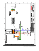
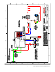
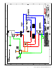
Boiler Applications Manual 800000026 Rev A A B C D 7 N L Power 6 P1 Boil 8 Pmp/Vlv DHW 9 10 10A 4 Low voltage 120V Note: See 2 boiler with DHW indirect tank drawing Heating Circulator Heat Demand From Thermostat/zone control 120V Input L N Setp Com DHW Dem Dem Dem Boiler Demand 3 5 2 4 1 10A Q Serie s boilers 2 boilers with DHW indirect tank 4 10A Stage 1 Stage 2 2 262 tN2 tN1/ Com 10K Sw UnO Boil Out 3 2 Outdoor Sensor Supply Sensor DHW Sensor Com DHW
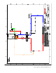
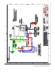
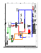
Boiler Applications Manual 800000026 Rev A A B C D 3 4 *May substitute for multi zone relay Low voltage 120V Note: See piping diagram Single Zone Priority DHW 120V 120 VAC INPUT N H DHW Pump Relay Aquastat For DHW 4 N/O Q boiler Single Zone Circuit with Prior ity DHW 4 4 N/C T R 6 N/O 24 VAC COM 2 5 3 4 5 6 8 DHW Pump 7 N 120V External controller 9 L 3 This is not an engineering drawing; it is intended only as a guide and not as a replacement for professional enginee
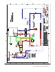
Boiler Applications Manual 800000026 Rev A A B C D 24V Input Low voltage 120V 4 Note: Switch positions and jumpers 120V Input 24V Input Note: 100% zone valve systems with DHW should use only the ZVC 406 Q boiler 4 Zone Valves with Priority DHW 4 MAIN END SWITCH POWER IN 2 EXTRA END SWITCH COM N/C 3 T 2 3 ZONE 1 5 4 6 1 2 3 2 3 7 1 System Circulator 1 ZONE 1 T T stat 4 T 1 2 3 ZONE 2 ZONE 2 T T stat 8 N 120V External controller 9 L 4 3 This is not an e
Boiler Applications Manual 800000026 Rev A
Notes 25 Boiler Applications Manual 800000026 Rev A
Boiler Applications Manual 800000026 Rev A 6/2010