Installation & Servicing Instructions High efficiency condensing gas boiler Q85SN/Q130SN/Q175SN/Q205SN/Q175CN Q85SP/Q130SP/Q175SP/Q205SP/Q175CP CAUTION! Read this manual thoroughly before installing, servicing, putting into operation or using this boiler and vent system. WARNING! Improper installation, adjustment, alteration, service or maintenance can cause property damage, personal injury (exposure of hazardous materials)* or loss of life. Refer to the user's information manual provided with this boiler.
Contents of instructions These installation instructions contain important information for the safe installation, start-up and maintenance of boilers with capacities 85,000 through 205,000 BTU/hr. These installation instructions are intended for licensed professionals, who have the necessary knowledge and are approved for working on heating and gas systems.
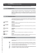
Content 2 3 4 5 6 Safety and general instructions ........................................................4 1.1 Designated use ...................................................................4 1.2 Hazard definitions ................................................................4 1.3 Symbol definitions ...............................................................4 1.4 The following instructions must be followed ........................5 1.5 Follow these instructions for the space heating water ....
1 Safety and general instructions Please observe these instructions in the interest of your own safety. 1.1 Designated use The boiler is designed for heating water for a central heating system and, if applicable, generating domestic hot water. The boiler is delivered with a burner controller (MCBA) pre-installed.The boiler can be fitted with a modulating outdoor reset sensor ARV12 (included with the boiler) or an On/Off thermostat or relay panel end switch (accessories). 1.
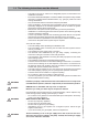
1.4 The following instructions must be followed - The boiler must only be used for its designated purpose, as described in the Installation Instructions. Each unit is fitted with a data plate. Consult the details on this plate to verify whether the boiler is compliant with its intended location, e.g.: gas type, power source and venting classification. Only use the boiler with the accessories and spare parts listed.
i NOTICE Chemicals that are corrosive in nature should not be stored or used near the boiler or vent termination. 1.5 Follow these instructions for the space heating water Unsuitable heating system water can cause the formation of scale or sludge, which affects system efficiency. It can also cause corrosion and reduce life of the heat exchanger. – You must follow Rinnai guidelines for boiler water quality. – Thoroughly flush the system prior to filling. – Follow the Rinnai cleaning instructions.
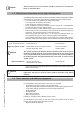
1.7 Relevant Installation, Service and User manuals – Approved vent system – Rinnai Boiler Applications Manual – User manual 1.8 Disposal – Dispose of the boiler packaging in an environmentally sound manner. – Dispose of components of the heating system (e.g. boiler or control device), that must be replaced in an environmentally responsible manner.
3 Description of the boiler Room sealed boiler The boiler retreives its combustion air from outside then discharges the flue gasses to the outside. Condensing Retrieves heat as much as possible from the flue gasses. Water condensates on the heat exchanger. Modulating Stepless higher or lower burning according to the heat demand. The Rinnai Q boiler is a room sealed, condensing and modulating central heating boiler, with an optional integrated DHW cylinder (integrated DHW on the Q175C only).
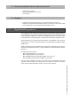
4 Packaging and transportation 4.1 Scope of delivery The boiler is supplied ready for use. • Please check if the packaging is intact. • Check if all the items listed are included in the delivery.
5 Installation 5.1 Requirements for the installation room ! DANGER - - Installation & Servicing Instructions Rinnai Q-Series - 10 The room where the boiler will be placed must always be free from freezing conditions. Do not store or use gasoline or other flammable vapors and liquids in the vicinity of this or any other appliance. Never use or store any chlorinated detergents or halogenated hydrocarbons (e.g. in spraycans, solvents and detergents, paints, adhesives) in proximity of the boiler.
5.2 Fitting the boiler i NOTICE i NOTICE - Remove the packaging materials. - Do not tear the packaging. Take notice of the presence of the mounting template at the inside of the carton wrapper. Lay the boiler on its back during unpacking. When unpacking, the casing can be removed from the boiler. This part can be kept apart during installation. It must be placed on the boiler and fixed with the screw behind the door before the boiler is started up.
5.
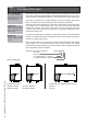
Dimensions A B C D E F G H J K L N O P Q R S T U V1 V2 W X Y Z aa Height Width Depth Left side / vent Center to center / vent and air supply Back / vent Left side / gas pipe Left side / supply pipe Left side / return pipe Left side / condensate pipe Left side / expansion pipe Left side / cold water pipe Left side / hot water pipe Pipe length of g* Pipe length of c* Pipe length of f and r* Pipe length of e, k and w* Back / Center of pipe c* Back / Center of pipe g* Back / Center of pipe f, r, e, k and w* B
Dimensions Connection for combustion air supply and vent system g f1 r1 c g f1 r1 c g f1 r1 c e k w t f2 boiler connections r2 f2 r2 Installation & Servicing Instructions Rinnai Q-Series Vent system / Combustion air supply g Gas pipe Supply pipe boiler side - f1 system side - f2 Return pipe boiler side - r1 system side - r2 Condensate pipe c 14 Expansion pipe e Cold water pipe k Hot water pipe w connection diameters r2 figure 3 Boiler type Supply pipe indirect tank.
5.3.1 Plumbing Kits Rinnai boilers are supplied with a Plumbing kit from factory. Find below the dimensions. See chapter 6.1 for additional information. Plumbing Kit 2 Suitable for: Q85SN / Q85SP Q130SN / Q130SP 8.6” 219mm 4.7” 3.9” 119mm 100mm 2.0” 50mm 17.6” 448mm 2.1” 54mm 5.2” 131mm 9” 229mm 14.2” 360mm 142 [5.6”] 16.4” 416mm Plumbing kit 2 Suitable for: Q175SN / Q175SP Q175CN / Q175CP Q205SN / Q205SP 15” 381mm 2.0” 50mm 4.7” 120mm 10.2” 260mm 18.6” 474mm 2.1” 54mm [5.6” 142mm 5.
5.3.2 Clearences from the boiler ceiling Min. 10" / 250mm 2" 50 24" 600 2" 50 wall 15.
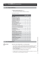
5.4 Technical specifications Q-Series Combi Q175CN Q175CP Q85SN Q85SP Q130SN Q130SP Q175SN Q175SP Q205SN Q205SP 175,000 51 157,000 45.9 172,400 50.2 167,500 48.8 85,000 25 77,000 22.5 84,000 24.7 82,000 24.1 130,000 38 117,000 34.2 127,600 37.3 124,900 36.5 175,000 51 157,000 45.9 172,400 50.2 167,500 48.8 205,000 60 184,000 54.0 202,200 59.1 196,100 57.4 % 98.5 98.8 98.2 98.5 98.5 % % W W V/Hz A 95.
6 Connecting the boiler The boiler has the following connection pipes; - The central heating circuit pipes. These must be connected to the Plumbing Kit by means of adapter fittings. See further chapter 6.1; - The gas supply pipe. It is provided with a 3/4" male thread into which the tail piece of the gas valve can be screwed. See further chapter 6.4; - The condensation drain pipe. It consists of an oval 1" (24 mm) plastic pipe. The drain pipe can be connected to this by means of an open connection.
P Low Loss Header T V1 V2 Service valve Service valve 11 1 7 2 6 5 8 9 3 10 4 1. 2. 3. 4. 5. 6. 7. 8. 9. 10. 11.
6.1.1 Plumbing Kit installation Rinnai supplies specific Plumbing Kits with each boiler type, which must be fitted directly underneath the boiler on the supply and return pipe. Find in chapter 5.3 the dimensions. Use of the Rinnai boiler without the plumbing kit will void the warranty. i NOTICE i NOTICE - i To protect the entire heating system we recommend installing a dirt particle trap in the return circuit. When the boiler is installed to an existing heating system this trap is required.
- Boiler system flushing (Not Boiler heat exchanger) When replacing an existing boiler the heating system should be flushed with the old boiler in place before the new boiler is added to the system. If the old boiler has already been removed a bypass must be piped in when the new boiler is installed in order to facilitate the flushing of the system. The boiler must be valved off from the system, while the system is flushed.
13. If the installation is a zone system be sure to purge out each zone individually 14. Close the auto feed on the system (F1) 15. Close the return side purge station (BD2) and disconnect the hose (H3). 16. Open the main valve on the system return (V3) 17. Close the bypass valve below the plumbing kit (V4). 18. Open shutoff valves on both the supply and return connections on the plumbing kit (V1 and V2). 19. Clean out the dirt trap 20. Test the pH of the water that will be used for filling the system 21.
If the installation resistance is over the stated value; the pump will rotate at maximum capacity and the load will be adjusted until an acceptable temperature difference between supply and return water has been obtained. If, after this, the temperature difference is still not acceptable then the boiler will switch off and wait until an acceptable temperature has arisen. If an unacceptable temperature is detected, the control will repeatedly try to achieve water flow over the boiler.
6.1.2 Side mounting kit for the Low Loss header A side mounting kit for the low loss header is available as an accessory. This kit relocates the low loss header from directly below the boiler to the left side of the boiler only. The kit includes all the parts required to relocate the low loss header including all mounting brackets and material. This kit provides an alternative to for installations with height limitations and allows for an alternative piping installation.
6.2 Boiler expansion tank An expansion tank must be part of the central heating system. The expansion tank must be appropriate to the water content of the installation. The pre-charge pressure depends on the installation height above the mounted expansion tank. The expansion tank is NOT a part of the delivery and should be sourced locally. Please refer to the expansion tank manufacturer for further information. The Combi boiler Q175C is equipped with an expansion tank connection.
6.4 Gas connection ! DANGER Only work on gas lines if you are licensed for such work. If these instructions are not followed exactly, a fire or explosion may result causing property damage, personal injury or death. ! WARNING Rinnai wall mounted boilers are built to run on Natural Gas or Propane Gas. The gas type the boiler is suitable for is indicated on the packaging and on the boiler by a blue label with Natural Gas or a green label with Propane Gas and on the identification plate on the boiler.
6.4.2 i NOTICE Gas connection with propane gas The gas supply connection must comply with local regulations or, if such regulations do not exist, with the National Fuel Gas Code, ANSI Z 223.1. For Canada, the gas connection must comply with local regulations or, if such regulations do not exist, with the CAN/CSA B149.1, Natural Gas and Propane Installation Code. Pipe sizing for propane gas - Contact gas supplier to size pipes, tanks, and 100% lockup gas pressure regulator.
! Do NOT use toxic chemicals, such as those used for boiler treatment in potable water heating systems used for space heating. DANGER The sanitary water pipes can be connected to the installation by use of adapter fittings. The cold water inlet on the Combi boilers must be equipped with the following components (counted in the water flow direction):Flow regulator valve (supplied), Safety group, Expansion vessel 87 PSI / 6bar (potable water, blue). A flow regulator valve is supplied with the boiler.
6.5.3 DHW Expansion Tank A domestic water expansion tank could be required by local code. Check local code to determine if it is required. If a combi boiler is installed in a closed water supply system, such as one having a backflow preventer in the cold water supply line, means shall be provided to control thermal expansion. Contact the water supplier or local plumbing inspector on how to control thermal expansion. 6.5.
- - The discharge from the pressure relief valve should be piped to the ground or into a drain system to prevent exposure or possible burn hazards to humans or other plant or animal life. Follow local codes. Water discharged from the relief valve could cause severe burns instantly, scalds, or death. The pressure relief valve must be manually operated once a year to check for correct operation. The relief valve should be added to the hot water outlet line according to the manufacturer instructions.
6.7 Vent system and air supply system Provisions for combustion and ventilation air must be made in accordance with section, Air for Combustion and Ventilation of the National Flue Gas Code, ANSI Z223.1, or Sections 7.2, 7.3 of 7.4 of CAN/CGA B149.1, Installation Codes, or applicable provisions of the local building codes. - i NOTICE 6.7.1 Do not store chemicals near the boiler or in rooms where the air is being supplied to the boiler. See the list on page 10.
6.7.
6.7.
6.7.3 Installation of the vent system i NOTICE Consult local and state codes pertaining to special building code and fire department requirements. Adhere to national code requirements. i NOTICE Follow the listed maximum length of vent systems, which are boiler output dependent. The maximum permissible lengths are listed in table 9, chapter 6.7.7. The maximum permissible lengths are listed in table 9, chapter 6.7.7. Decide how to install the exhaust and air intake system.
6.7.3.1 Boiler conversion from concentric to parallel A. 1. Push the 2 clips slightly outwards A 1 B. 2. Pull the concentric adaptor out of the boiler 3. Press the cover in the connection at the back from inside out B 2 3 C 10 9 7 4 6 8 C. 4. Push the 3" adapter into the connection at the back of the boiler (= air intake) 5. Pull the rubber seal around the bottom of the exhaust connector 6. Push the exhaust connector in the boiler, in the boiler exhaust pipe until 'CLICK' 7.
6.7.4 Recommended vent/air intake terminal position Terminals should be positioned as to avoid products of combustion entering openings into buildings or other vents. Maintain 12” of clearance above the highest anticipated snow level or grade or, whichever is greater. Please refer to your local codes for the snow level in your area.
i i NOTICE See Boiler Applications manual for additional venting information. NOTICE The termination shall be at least 4 feet (1,220 mm) for the US and 6 feet (1,830 mm) for Canada distance from electric meters, gas meters, regulators and relief equipment. (for room air application only) ! CAUTION Horizontal vent systems should always be installed sloping towards the boiler (min. 21 mm/m, 1/4”/ feet), in order to avoid condensate retaining in the vent system.
Fittings or Piping Equivalent PVC feet 45 degree elbow 3 90 degree elbow 6 plastic pipe per foot 1 concentric vent kit 3 12" (300 mm) minimum 12" (300 mm) minimum Equivalent friction loss of PVC/CPVC EXHAUST INTAKE 12" (300 mm) minimum ! table 8 12" (300 mm) minimum 12" (300 mm) minimum Terminal positions PVC 6.7.5 m 0.91 1.83 0.30 0.
6.7.6 ! DANGER Dimensioning of the exhaust and air intake duct The wall mounted boiler must be vented and supplied with combustion and ventilation air as described in this section. Ensure the vent and air piping and the combustion air supply comply with these instructions regarding vent system, air system, and combustion air quality. Inspect finished vent and air piping thoroughly to ensure all are airtight and comply with the instructions provided and with all requirements of applicable codes.
6.7.7 Combustion air and vent piping lengths. In the table below you will find the maximum equivalent pipe length of the vent/air system based on 3" diameter. These lengths are for single pipe (room air), twin pipe, and concentric venting systems.
6.7.8 Calculation of compensation factor The compensation factor eliminates or reduces the natural effect of derate of maximum input caused by the resistance of the vent system and/or the impact of the altitude. 1. Determine the Compensation Factor Vent System CF(V) in the table below. Eq. length (ft) Q85 min 0 11 21 31 41 61 81 max 10 20 30 40 60 80 100 0 0 0 1 2 3 4 Boiler type Q130 Q175 CF (V) 0 0 0 2 2 4 4 6 6 10 8 15 10 n.a. Q205 0 3 6 10 n.a. n.a. n.a.
6.7.9 Room Air System (indoor combustion air) When using indoor air, Rinnai strongly recommends the use of an indoor air filter, P/N 808000025. ! This boiler requires adequate combustion air for ventilation and dilution of flue gases. Failure to provide adequate combustion air can result in unit failure, fire, explosion, serious bodily injury or death. Use the following methods to ensure adequate combustion air is available for correct and safe operation of this boiler.
Confined Space: (Small Room, Closet, Alcove, Utility Room, Etc.) A confined space is defined in the NFPA #54 as "a space whose volume is less than 50 cubic feet per 1000 Btu/hr (4.8 m3 per kW per hour) of the aggregate input rating of all appliances installed in that space." A confined space must have two combustion air openings.
Using Indoor Air For Combustion When using air from other room(s) in the building, the total volume of the room(s) must be of adequate volume (Greater than 50 cubic feet per 1000 Btu/hr). Each combustion air opening must have at least one square inch of free area for each 1000 Btuh, but not less than 100 square inches each. Using Outdoor Air For Combustion Outdoor air can be provided to a confined space through two permanent openings, one commencing within 12 in.
7 ! External domestic hot water tanks WARNING Note the local codes for requirements for connecting an external hot water cylinder to the boiler. The installation must comply to these codes. Depending on the domestic hot water requirements and comfort preferences various external hot water tanks can be connected to the boiler. Connecting an external hot water tank to the Q175C is NOT possible. Connecting an external hot water tank to the Q-Series solo boilers can be done in 2 ways: 1.
8 Electrical connections The electrical connections to the boiler must be electrically grounded in accordance with all applicable local codes and the latest revision of the National Electrical Code, ANSI/NFPA-70. Installations should also conform with CSA C22.1 Canadian Electrical Code Part 1 if installed in Canada.
i The Rinnai room thermostat and controls must be connected to their allocated connections. All other types or makes of room thermostats or controls which are used must have a Volt free contact. NOTICE When using an on/off thermostat or control, it may be necessary to calibrate the anticipating resistance to prevent too high temperature fluctuations. As a standard rule this means mercury thermostats. This resistance wire is present in the Control Tower and must be connected to terminals 23 and 27.
electrical diagram 2 Amp. max. Installation & Servicing Instructions Rinnai Q-Series X7 ! 120V T 220°F 120V 120V figure 28 CAUTION Label all wires prior to diconnection when servicing or replacing controls.
Installation & Servicing Instructions Rinnai Q-Series electrical ladder diagram figure 28a
9 Boiler controls The boiler is provided with a fully automatic microprocessor control, called CMS Control Management System. This control simplifies operation by undertaking all major control functions. Initially when power to the unit is switched on it will remain on standby. There is no indication LED on, until one of the program buttons is pressed. The control panel display will show the relevant state. When the boiler installation is empty the display will show FILL.
9.1 Explanation of the function buttons 1 2 3 7 4 5 6 8 Boiler control panel i NOTICE figure 29 Only licensed professionals who are trained for servicing these boilers are permitted to make alterations in the controller to calibrate the boiler to the installation. 1. Display. See previous page for further information. 2. ON-OFF Switch This switch turns the power supply to the boiler on or off. ! i CAUTION Only turn the boiler off using this switch, when the burner is off. 3.
10 Starting up: Filling and de-aerating the boiler and installation ! CAUTION i NOTICE i NOTICE ! WARNING CAUTION Observe the following rules of safety: - All work on the unit must take place in a dry environment. - Rinnai units may never be in operation without their housing, except in connection with maintenance or adjustments (see Chapter 13 and 14). - Never allow electrical or electronic components to come into contact with water.
Freeze protection Freeze protection for new or existing systems must use glycol that is specially formulated for this purpose. This includes inhibitors, which prevent the glycol from attacking the metallic components. This should be for multi-metallic components. Make certain to check that the system fluid is correct for the glycol concentration and inhibitor level. The system should be tested at least once a year and as recommended by the producer of the glycol solution.
13 If A XX appears on the display, wait for 17 minutes; 14 Check the water pressure and if necessary top it up to 16 to 18 PSI (1.1 and 1.3 bar) 15 Close the filling loop; 16 Press the ‘STEP’-button; 17 Be sure that the filling loop is closed. 18 After the automatic de-aeration program (A XX) is finished the boiler will return to the Good state or Technical read out. Check the water pressure regularly and top off the installation when necessary.
FOR YOUR SAFETY READ BEFORE OPERATING WARNING: If you do not follow these instructions exactly, a fire or explosion may result causing property damage, personal injury or loss of life. A. This appliance does not have a pilot. It is equipped with an ignition device which automatically lights the burner. Do NOT try to light the burner by hand. B. BEFORE OPERATING smell all around the appliance area for gas. Be sure to smell next to the floor because some gas is heavier than air and will settle on the floor.
11 Adjustments When the boiler is installed the software has already been pre-programmed at the factory. All software adjustments of the boiler control are already pre-programmed for a heating system with radiators/convectors with a supply temperature of 176°F. The adjustments are described in the Parameter chapter on the following page.
Parameter Mode PARA . 1 2* FACTORY . 176°F 00 DESCRIPTION . maximum supply temperature CH type of CH installation: No pre-selection made. Radiators, air heating, or convectors: T max. supply 176°F K factor heating curve 2.3; gradient 10°F/min; gear differential 10°F RANGE . 68 - 176°F 00 - 04 00 01 DO NOT USE max. 00 02 under floor heating with radiators as additional heating: T max. supply 140°F; K factor heating curve 1.
Service Mode 1 2 3 4 SERV OFF OFF OFF OFF DESCRIPTION boiler in operation with burner function on fan adjustable and burner off pump adjustable with burner on showroom position ON = active and OFF = non active RANGE OFF - max. OFF - max. OFF - max. ON - OFF . . . . VALUE Error Mode ERRO DESCRIPTION VALUE Err.L - Err.5 Last saved error until 5 last previous errors 1 error code 2 operation status boiler 3 °F supply water temperature T1 4 °F return water temperature T2 5 kW load (.. x3415 = ..
11.2 Activating factory settings (green button function) To activate the factory settings again please follow the next procedure (Note: all altered adjustments will be set back to the original factory settings that are accessible in the current service level the boiler is in either user or 123): - Select, when necessary, the technical read out; - Select with the MODE-button chapter PARA; - Press the STORE-button. The word "Copy" will appear and factory settings are active again.
13 i Commissioning Work on the boiler must be carried out by a licensed professional, using correctly calibrated instruments with current test certification. These installation instructions are intended for licensed professionals, who have the necessary knowledge and are approved for working on heating and gas systems. NOTICE Before the boiler is fired, ensure that the boiler and the system are well de-aerated and free of air. Purge the gas line between the gas meter and the boiler.
13.1 Testing for gas leaks Prior to start-up of the boiler you must check the external tightness of the gas supply valve and confirm this in the start-up report. WARNING - ! DANGER Before leak testing the boiler, ensure all parts of the boiler such as electronics and wiring are properly covered and protected from the leak testing agent. Do not spray the leak testing agent onto cables, plugs, electrical connection lines or electronic circuit boards. Do not allow it to drip onto them either.
13.3 Checking the O2 i NOTICE ! WARNING The O2 percentage setting is required to be checked at commissioning, maintenance and faults and adjusted if needed. The O2 percentage is required to be checked and adjusted after a conversion from NG to LP or from LP to NG. This process must be done with a calibrated combustion analyzer that has been set to the correct gas type. This can be checked by means of the following procedure: - Remove the black cover of the gas valve by unscrewing the sealed screw.
- Replace the black cover on the gas valve and secure it with the screw. For high altitude installations, elevations between 2000 ft and 4500 ft (600 m and 1350 m), in Canadian area it is required to fill out the High Altitude Label. Place the filled out High Altitude Label on the controller supporting frame, on the left side of the rating plate. High Altitude Label (example) 13.
13.5 Installing the casing CLOSE 1 - Install the airbox and close all snap locks. See figure 34; - Install the metal casing on the boiler; - Lock the casing by using the screw behind the door. See figure 35. 2 Installing air box figure 34 3 2 1 Installing casing 14 i figure 35 Maintenance Maintenance or changes to the boiler may only be carried out by a licensed professional.
The air box OPEN Opening air box - Remove the transparant air box (figure 37); - Clean the box with a cloth with a simple (non-abrasive) cleaning agent; figure 37 14.2.1 Visual inspection for general signs of corrosion - 14.2.2 Check all gas and water pipes for signs of corrosion. Replace any pipes that are corroded. Measuring the ionization current See subsection 13.5 “Measuring the ionization current”. 14.2.3 Measuring the inlet gas pressure See subsection 6.4.1 and .
14.3 Maintenance activities i NOTICE 2 9 1 4 The fan unit and burner cassette (figure 38 to 4) (every 4 year maintenance) - Remove the electrical connection plug from the gas valve (1) and fan motor (2); - Loosen the nut (3) of the gas pipe under the gas valve; - Replace the gasket with a new one; - Loosen the front cross head screw (4) of the black plastic silencer; - After this turn the two clamping rods (9 and 10) ¼ turn and remove them by pulling them forward.
9 10 8 7 Siphon figure 41 13 14 12 Condensate trap and condensate tray (figure 41-43) (2 and 4 year maintenance) Step 1: Condensate trap - First remove the condensation cup (7); Check this for impurities. If there is not a lot of impurities it is not necessary to clean the condensate tray (Go to Step 3).
Visual inspection of the flame (2 and 4 year maintenance) The burner must flame evenly over the entire surface when operating correctly. The flame must burn with a clear, blue, stable flame. Check the flame through the inspection glass in the ignition probe (fig. 44). The flame pattern should be as shown in the figures below.
15 Parts of the boiler 4 2 1 3 7 5 16 15 6 8 17 T1 P1 19 T2 T3 F 18 R C 9 E K 10 11 12 13 Rinnai Q 1 2 3 4 5 6 7 8 W 14 figure 45 heat exchanger ignition unit fan unit air inlet damper gas valve automatic de-aerator ceramic burner cassette DHW tank (Q175C) 9 10 11 12 13 14 operating panel Control Tower (CMS) water filter return CH three-way valve (Q175C) circulation pump thermostatic mixing valve (Q175C) 15 exhaust 16 combustion air supply 17 air box 18 CSA Data Plate (serial nu
16 Blocks and Errors 16.1 Error indication (short reference) A detected error is indicated on the display by means of blocking or error messages. A distinction should be made between these two messages due to the fact that blocking can be of a temporary nature, however, error messages are fixed lockings. The control will try its utmost to prevent locking and will temporarily switch off the unit by blocking it. The following is a list of some messages. Blocks with a number in the last 2 positions.
16.2 Blocks An error, which has been detected, is indicated on the display by a block message. Blocks can be temporary in nature. The controller will do everything possible to prevent a system lock and temporarily switching off the boiler as a result of a block. Please see below for a summary of blocks. Blocks with a figure on the last 2 characters. Description Solution External safety contact open Rectify error as a result of which by determining contact is open.
16.3 Errors Code Description Solution Incorrect flame formation. boiler has not been burning but an ionization flow (flame) has still been detected Check whether the ionization cable and/or the electrode are responsible for a possible short-circuit. Remove the plugs from the ionization cable connected to the control unit and to the electrode. Now using a universal meter take a measurement between the ionization connection and the ground, now refit it part by part until a short-circuit takes place.
Code Description Solution Control unit error 1 Anticipation resistance wire not When a power stealing room stat device is placed the connection terminal present needs to be provided with the special anticipation resistance wire. 2 Software error control unit. Replace the control unit. The controller will automatically load the program into the new control unit. Control unit error Incorrect data will be detected in case of a poor connection between the control unit and the display.
Code Description Solution No signal from the fan The fan is not running. Check the wiring to the fan and the control unit and/ or the 24 volt power supply to the fan Wiring and voltage are OK and error is repeated. Replace the fan Negative pressure on vent system (pressure difference) Check vent system. Vent system and air intake system must be installed according installation instructions. IF vent system is OK: Replace fan internal shut down of supply sensor T1 Check the data in Error mode.
Description Solution contact for return sensor T2 open Check the data in Error mode. Boiler data during error: 1 Error = 37 2 Operational status = 00 3 Flow temp. = xx* 4 Return temp. = -22 5 kW burner = 00** 6 % pomp = xx* * = variable values **= x3415=BTU/hr Check the wiring. check the wiring for the sensor The wiring is OK but the error is repeated. Remove the plug from the flow sensor as a result of which Error 32 occurs Replace the sensor. Control unit error Software error control unit.
16.4 Other Errors Complaint Central heating but no domestic hot water Hot water but no central heating Central heating installation gets hot without being requested Installation & Servicing Instructions Rinnai Q-Series Insufficient quantity of hot water 76 Description 1. -Key of the DHW program is not switched on Solution Switch on DHW program on the Control Tower 2. Cylinder sensor or thermostat defective. Replace cylinder sensor or thermostat 3.
Complaint Description Solution Temperature drop of the DHW (Combi) 1. Flow reducing valve Check flow reducing valve for the correct type in accordance with the installation instructions temperature drop of the Solo hot water with the DHW cylinders radiators do not get hot enough or warming them up takes too long 3. DHW power for the boiler is set too low. -Check PARA chapter Step No. 43 - Check the functioning and wiring of the DHW sensor T3. 1.
02 01 Parts casing Q-Series / Pièces de l'habillage Série Q Installation & Servicing Instructions Rinnai Q-Series Pictured: E75CN, E110CN E75CP, E110CP m a n u a l WARNING! If you do not follow these instructions exactly, a fire or explosion may result causing property damage, personal injury or loss of life. - Do not store or use gasoline or other flammable vapors and liquids in the vicinity of this or any other appliance. - WHAT TO DO IF YOU SMELL GAS - Do NOT try to light any appliance.
CASING 25/38 CASING 51/60 CASING 51C DOOR CASING Q CPL. USER MANUAL Q-SERIES INSTALLATION MANUAL Q-SERIES BOILER CASING BOLT M5X16 (SET OF 5 BOLTS) Installation & Servicing Instructions Rinnai Q-Series 1 1 1 3 4 5 6 Item Description HABILLAGE 25/38 HABILLAGE 51/60 HABILLAGE 51C PORTE MANTEAU Q CPL. MODE D'EMPLOI SÉRIE Q INSTRUCTIONS D'INSTALLATION SÉRIE Q VIS DE L'HABILLAGE DE CHAUDIERE M5X16 (5 PAR PAQUET) Description Art. No.
61 44 63 62 60 59 83 56 55 54 53 52 51 47 46 45 43 41 40 39 38 37 49 36 35 34 33 32 64 31 30 Parts heat exchanger Q-Series / Pièces d'échangeur de chaleur Série Q Installation & Servicing Instructions Rinnai Q-Series
CLAMP BAR TOP PART H.EX. LONG TOP PART HEAT EXCH. SET OSS1 TOP PART HEAT EXCH. SET OSS2 TOP PART HEAT EXCH. SET OSS3/4 BOLT M 5X16 (5 PER PACKAGE) GASKET FAN/TOP PART H.EX.
61 44 63 62 60 59 83 56 55 54 53 52 51 47 46 45 43 41 40 39 38 37 49 36 35 34 33 32 64 31 30 Parts heat exchanger Q-Series / Pièces échangeur de chaleur Série Q Installation & Servicing Instructions Rinnai Q-Series
CAP DE-AERATOR SHR (3 PER PACKAGE) DE-AERATOR CHROME O-RING ø13,94X2,62 DE-AER. (2 PER PACKAGE) BOLT M 3X30 VERZ.DIN84/4.8 (3 PER PACKAGE) GASKET H.E./TOP PART OSS1 GASKET H.E./TOP PART OSS2 GASKET H.E./TOP PART OSS3/4 GASKET BURNER/TOP PART OSS1 GASKET BURNER/TOP PART OSS2 GASKET BURNER/TOP PART OSS3/4 BURNER CASSETTE SET OSS1 BURNER CASSETTE SET OSS2 BURNER CASSETTE SET OSS3/4 SET INSOLATION PIPE PLATE L+R O-RING ø17,12X2,62 PLUG HEATEXCH.
95 93 94 92 91 90 87 100 78 77 89 82 81 84 96 97 98 114 115 99 103a 103 112 113 Parts rear wall Q-Series / Pièces façade arrière Série Q Installation & Servicing Instructions Rinnai Q-Series 104a 104 116 101 111a 110 111 118 119 105 106 107 108a 108 109 117
COVER AIR SUPPLY Ø80mm CONCENTRIC FLUE ADAPTOR 80/125"MM GASKET AIR INTAKE ø80 SHR FLUE ADAPTER 80mm x 3" COVER AIR SUPPLY Ø125mm FLUE GAS SYSTEM PP SET OSS1 FLUE GAS SYSTEM PP SET OSS2 FLUE GAS SYSTEM PP SET OSS3/4 PLUG MEASURING POINT PARALLEL FLUE PIPE GASKET FLUE GAS PIPE PP GASKET AIR SUPPLY 5" AIR BOX BACK Q85S 7 Q130S AIR BOX BACK Q175S, Q175C & Q205S PLUG MEASURING POINT CONCENTRIC FLUE PIPE O-RING ø19.50X1.80 TRAP TRAY CONDENSATE DRAIN PIPE Q O-RING Ø12.42X1.
95 93 94 92 91 90 87 100 78 77 89 82 81 84 96 97 98 114 115 99 103a 103 112 113 Parts rear wall Q-Series / Pièces façade arrière Série Q Installation & Servicing Instructions Rinnai Q-Series 104a 104 116 101 111a 110 111 118 119 105 106 107 108a 108 109 117
CONNECTION SET 28 X 1" NPT CONNECTION SET 35 X 1 1/4" NPT PIPE 3WV-PUMP EXT. EXP.VESSEL Q CONNECTION SET 22 X 3/4" NPT FILTER RETURN PIPE Q THREE WAY V. HOUSING VC O-RING CARTRIDGE 3WV FILTER CAP O-RING ø25,07 X 2,62 3WV NUT M35 ø30 PIPE CYLINDER-3WV Q FITTINGS SET CYL. COMBI NUT M35 ø30 O-RING ø26.70 X 1.78 (3 PER PACKAGE) AIRBOX GASKET FLOW/ RETURN Q SERVICE CAP AIRB. Q FITTING GAS VALVE 3/4" O-RING ø21.89X2.62 GASLINE GASKET FITTING 3/4" GASV.
DHW sensor / sonde ECS Outdoor reset sensor / Sonde 158 T3 160 T4 151 P1 160 sonde pression eau water pressure sensor / interrupteur haute limite 130 156 159 flue gas sensor / sonde fumées 159 HLS high limit switch / 156 T5 return sensor / sonde retour 150 T2 reset exterieur supply sensor / sonde départ 152 T1 151 150 152 158 1 5 6 L N 4 230 V~ Pomp extern 3 L N 2 230 V~ Netaansl.
TRANSFO 120V/24V VIS 3,5X 9,5 GALV.D7983 (5 PAR PAQUET) BOITIER DE COMMANDE COMPLET HARNAIS Q RAC AUTOCOLLANT CONNECTEURS TERMINAL HARNAIS Q 120V + INTERRUPTEUR PRINCIPAL CONNECTEUR 2-POLES POURPRE CONNECTEUR 2-POLES NOIR CONNECTEUR 3-POLES VERT POMPE EXT.
DHW sensor / sonde ECS Outdoor reset sensor / Sonde 158 T3 160 T4 151 P1 160 sonde pression eau water pressure sensor / interrupteur haute limite 130 156 159 flue gas sensor / sonde fumées 159 HLS high limit switch / 156 T5 return sensor / sonde retour 150 T2 reset exterieur supply sensor / sonde départ 152 T1 151 150 152 158 1 5 6 L N 4 230 V~ Pomp extern 3 L N 2 230 V~ Netaansl.
NTC T2/T3 SONDE PRESSION EAU CABLE SONDE PRESSION EAU NTC T1/T3 ELECTRODE D'ALLUMAGE+JOINT OSS CABLE D'ALLUMAGE SHR HARNAIS VENTILATEUR 120V CABLE D'IONISATION SHR VENTILATEUR NRG 118 OSS1/2 VENTILATEUR G1G126 OSS3/4 HARNAIS VENTILATEUR 120V VANNE GAZ SONDE FUMEES CABLE INCL.
205a 205 200 204 206 207 208 209 202 211 212 210 213 Parts tank (Combi boilers) Q-Series / Pièces boiler (Chaudières combi) Série Q Installation & Servicing Instructions Rinnai Q-Series
MINI-TANK 6.6 GLN Q175C ADAPT.FITT+DOS.VLVE 4.75 GLN/MIN RED KNEE FITTING 15MM PIPE Ø15 COLD Q CONNECTION SET 15 X 3/4" NPT PIPE ø15 HOT-MIXING VALVE Q CROSS COMPR.FITTING 15MM Q PIPE Ø15 COLD MIXING VALVE Q THERM. MIX VALVE ø15 COMPR. Q PIPE Ø15 MIX Q FERRULE COMPR FITTING 15MM BRASS NUT 1/2" G BRASS COMPR. 15 STRAP CYLINDER/EXP.VESSEL FITTING SET CYLINDER COMBI Installation & Servicing Instructions Rinnai Q-Series 200 202 204 205 205A 206 207 208 209 210 211 212 213 Item Description MINI BOILER 6.
307 306 305 304 301 300 302 303 Parts plumbing kit Q-Series / Pièces kit hydraulique Série Q Installation & Servicing Instructions Rinnai Q-Series 308
KIT HYDRAULIQUE #2 POUR Q85S/Q130S KIT HYDRAULIQUE #3 FOR Q175S/Q175C/Q205S RACCORD BICON 28MM RACCORD BICON 35MM ECROU RACCORD BICON 28MM ECROU RACCORD BICON 35MM EMBOUT RACCORD BICON 28MM EMBOUT RACCORD BICON 35MM VANNE DE SECURITÉ KIT HYDRAULIQUE ISOLATION KIT HYDRAULIQUE 1/2 ISOLATION KIT HYDRAULIQUE 3 VANNE DE PURGE KIT HYDRAULIQUE VANNE DE SERVICE+RACCORD 1 1/4"NPT VANNE DE SERVICE+RACCORD 1 1/2"NPT COMPTEUR T/P AVEC VEROUILLAGE EAU 300 PLUMBING KIT #2 FOR Q85S/Q130S PLUMBING KIT #3 FOR Q175S/Q17
Installation & Servicing Instructions Rinnai Q-Series 18 96 Parts list vent system Vent Products Listed and Tested Vent Products for E75C, E110C, Q85S, QP85, Q130S, QP130, Q175S, Q175C and Q205S Manufacturer Descriptions Parts # Heatfab DGV 3"/5" Conc Air Intake Tee 3" DGV03TAD3 DGV 3"/5" Conc X 12" Length DGV03L12 Concentric DGV 3"/5" Conc X 31" Length DGV03L36 DGV 3"/5" Conc Horz Term Adapter DGV03HT DGV 3"/5" Conc Vert Term Adapter DGV03VT Rain Cap SGV300 3"- Adapter to fit into 80 mm Flue Collar ada
Descriptions 3” PVC Concentric Vent Termination Parts # 1CT0303 Manufacturer CentroTherm Descriptions 3"/4" B-Vent Chimney Cover 3"/5" B-Vent Chimney Cover 3"/6" B-Vent Chimney Cover 3"/7" B-Vent Chimney Cover 3'' Connector Ring 3" Support Clamp 3'' Spacer 3" Screens PPs-UV Black 3'' Bird Screen SS 3'' Wall Plate Black 3'' Wall Plate White 3'' Twin Pipe to 3''/5'' Concentric Adaptor 3" Base Support 3'' Chimney Cover SS w/PPs-UV End Pipe 3'' Chimney Cover PPs-UV Black 3'' Chimney Cover SS w/SS End Pipe 3"
Vent Manufacturer Contact Information for Installation Instructions and Parts Lists: Heat-Fab Telephone: 800-772-0739 Fax: 413-863-4803 cystsvc@heat-fab.com www.heatfab.com IPEX Telephone: 800-463-9572 905-403-0264 Fax: 905-403-9195 www.ipexamerica.com Simpson Dura-Vent Telephone: 518-463-7284 Fax: 518-463-5271 sales@duravent.com www.protechinfo.com 20 Rinnai/Ubbink Telephone: 800-621-9419 Fax: 678-829-1666 www.rinnai.us York International Telephone: 405-364-4040 877-874-7378 www.york.
Appendix A - Outoor Reset Sensor Data R 25 °C 12 k: R 100 ° C 950 : B25/85 3750 K Temperature coefficient -4,2 %/K Temp [°C] NTC [kOhm] -30 171.70 -20 98.82 -10 58.82 0 36.10 10 22.79 20 14.77 200 180 160 NTC [kOhm] 140 120 100 80 60 40 12.00 30 9.81 40 6.65 50 4.61 60 3.25 70 2.34 80 1.71 90 1.27 100 0.95 110 0.73 120 0.
Appendix B - Resistance table NTC sensors Installation & Servicing Instructions Rinnai Q-Series Temp °F 100 -4 -0.4 3.2 6.8 10.4 14 17.6 21.2 24.8 28.4 32 35.6 39.2 42.8 46.4 50 53.6 57.2 60.8 64.4 68 71.6 75.2 78.8 82.4 86 89.6 93.2 96.8 100.
Instructions d'installation & d'entretien Chaudière gaz à condensation haut rendement Q85SN/Q130SN/Q175SN/Q205SN/Q175CN Q85SP/Q130SP/Q175SP/Q205SP/Q175CP ATTENTION! Lisez entièrement ce manuel avant l’installation, l’entretien, la mise en service ou l’utilisation de cette chaudière et du système d'évacuation fumées.
Contenu des instructions Ces instructions d’installation contiennent d’importantes informations pour l’installation, le démarrage et la maintenance en toute sécurité des chaudières d’une capacité de 85 000 à 205 000 BTUH. Ces instructions d’installation sont destinées aux professionnels agréés qui ont une connaissance suffisante et sont agréés pour travailler sur les systèmes de chauffage et de gaz.
Sommaire 2 3 4 5 6 Sécurité et instructions générales ................................................104 1.1 Utilisation prévue .............................................................104 1.2 Définition des dangers .....................................................104 1.3 Définition des Symboles ..................................................104 1.4 Les instructions suivantes doivent être suivies ..............105 1.5 Suivez ces instructions pour l’eau de chauff. des locaux 106 1.
1 Sécurité et instructions générales Veuillez observer ces instructions dans l’intérêt de votre propre sécurité. 1.1 Utilisation prévue La chaudière est conçue pour chauffer de l’eau pour un circuit de chauffage central et, si d’application, pour produire de l’eau chaude sanitaire. La chaudière est livrée avec une commande brûleur (MCBA) préinstallée.
1.4 Les instructions suivantes doivent être suivies - La chaudière ne doit être utilisée que pour son usage prévu, tel que décrit dans les instructions d’installation. Chaque appareil est équipé d’une plaque signalétique. Consultez les détails de cette plaque pour vérifier si la chaudière est conforme à son emplacement prévu, par exemple : type de gaz, source d’alimentation et classification d’évacuation. N’utilisez la chaudière qu’avec les accessoires et les pièces de rechange indiqués dans la liste.
- ! AVERTISSEMENT ! AVERTISSEMENT i REMARQUE Ne pas entreposer ni utiliser d'essence ni d'autres vapeurs ou liquides inflammables dans le voisinage de cet appareil ou de tout autre appareil. QUE FAIRE SI VOUS SENTEZ UNE ODEUR DE GAZ: - Ne pas tenter d'allumer d'appareils. - Ne touchez à aucun interrupteur. - Ne pas vous servir des téléphones dans le bâtiment où vous vous trouvez. - Appelez immédiatement votre fournisseur de gaz depuis un voisin. Suivez les instructions du fournisseur.
1.
3 Description de la chaudière Chaudière à chambre étanche La chaudière aspire son air de combustion de l’extérieur puis évacue les fumées vers l’extérieur. Condensation Récupère autant que possible la chaleur des fumées. L’eau se condense sur l’échangeur de chaleur. Modulation Combustion continue plus ou moins forte selon la demande de chaleur.
4 Emballage et transport 4.1 Contenu de la livraison La chaudière est livrée prête à être utilisée. • Veuillez vérifier si l’emballage est intact. • Vérifiez si tous les éléments de la liste sont inclus dans la livraison. Le kit fourni contient : Chaudière avec: Sonde extérieure ARV12 Anneau bicon Ø15 laiton Anneau bicon Ø22 laiton Anneau bicon Ø28 laiton Anneau bicon Ø35 laiton Boulon M5X16mm Chapeau aspiration air Ø120/Ø80 Joint système d'évacuation ø80 Sécurité traction de cable alim.
• 5 Les chaudières emballées doivent toujours être soulevées et transportées par deux personnes, ou bien vous devez utiliser un chariot manuel ou un équipement spécial pour le transport. Installation 5.1 Exigences pour la chaufferie ! DANGER - - Installation & Servicing Instructions Rinnai Q-Series - 110 La pièce dans laquelle la chaudière doit être installée doit toujours être protégée du conditions de geler.
5.2 Raccordement de la chaudière i REMARQUE i REMARQUE - Retirez le matériel d’emballage. - Ne déchirez pas l’emballage. Repérez la présence du gabarit de montage à l’intérieur de l’emballage en carton. Posez la chaudière sur le dos pendant son déballage. Lors du déballage, l’habillage peut être retiré de la chaudière. Cette partie peut être conservée à l’écart pendant l’installation.
5.
Dimensions A B C D E F G H J K L N O P Q R S T U V1 V2 W X Y Z aa Hauteur Largeur Profondeur Côte gauche / évacuation d'axe en axe évacuation et aspiration air Arrière / évacuation Côté gauche / conduite gaz Côté gauche / conduite départ CC Côté gauche / conduite retour CC Côté gauche / conduite condensats Côté gauche / conduite vase d'expansion Côté gauche / conduite eau froide Côté gauche / conduite eau chaude Longueur conduite de g* Longueur conduite de c* Longueur conduite de f et r* Longueur conduite
Dimensions Raccordement pour l’aspiration air de combustion et du système d’évacuation fumées g f1 r1 c g f1 r1 c g f1 r1 c e f2 r2 Raccordements de la chaudière f2 r2 Conduite retour CC Installation & Servicing Instructions Rinnai Q-Series Conduite condensation 114 g côté chaudière - f1 côté système - f2 côté chaudière - r1 côté système - r2 c e Conduite eau froide k Conduite eau chaude w Diamètre des raccordements r2 Solo Q85SN/Q85SP Q175SN/Q175SP Q130SN/Q130SP Q205SN/Q205SP Condu
5.3.1 Kits hydraulique Rinnai équipe chaque type de chaudière d’un kit hydraulique. Vous trouverez ci-après les dimensions. Voir les informations supplémentaires au Chapitre 6.1. 8.6” 219mm 4.7” 3.9” 119mm 100mm Kit hydraulique 2 Convient à: Q85SN / Q85SP Q130SN / Q130SP 2.0” 50mm 17.6” 448mm 2.1” 54mm 5.2” 131mm 9” 229mm 14.2” 360mm 142 [5.6”] 16.4” 416mm kit hydraulique 2 figure 4 15” 381mm Convient à: Q175SN / Q175SP Q175CN / Q175CP Q205SN / Q205SP 2.0” 50mm 4.7” 120mm 10.2” 260mm 18.
5.3.2 Espaces autour de la chaudière plafond Min. 10" / 250mm 2" 50 24" 600 2" 50 mur 15.
5.4 Spécifications techniques Séries Q Combi Débit calorifique sur valeur haute CC BTU/hr kW Qn Débit calorifique non-condensé CC BTU/hr kW Qn Débit calorifique EN677 rendement CC BTU/hr kW Qn Débit calorifique AFUE CC BTU/hr kW Rendement à 98.
6 Raccordement de la chaudière La chaudière est équipée des conduites de raccordement suivants : - Les conduites du circuit de chauffage central. Ils doivent être raccordés au kit hydraulique à l’aide de raccords d’adaptateur. Voir la suite au chapitre 6.1 ; - Le conduite d’alimentation gaz. Il est fourni avec un filetage mâle en 3/4" dans lequel le bout du raccord du robinet gaz peut être vissé. Voir la suite au chapitre 6.4 ; - La conduite d’évacuation des condensats.
P Bouteille casse-pression T V1 V2 Vanne d'isolement Vanne d'isolement 11 1 7 2 6 5 8 9 3 10 4 1. 2. 3. 4. 5. 6. 7. 8. 9. 10. 11. vanne d'isolement circulateur de système vanne d'inspection vanne d’équilibrage purgeur chaudière collecteur d'impuretés séparateur d'air vanne de remplissage automatique clapet anti-retour vase d'expansion by-pass pour rinçage de l'installation fig.
6.1.1 Installation du kit hydraulique Rinnai fournit des kits hydrauliques spécifiques avec chaque type de chaudière, qui doivent être raccordés directement sous la chaudière au tuyau départ et retour. Consultez le chapitre 5.3 pour les dimensions l’utilisation de la chaudière Rinnai sans le kit hydraulique peut faire annuler la garantie.
Rinçage du circuit de la chaudière (pas l’échangeur de chaleur de la chaudière) Lors du remplacement d'une chaudière existante, l’installation de chauffage doit être rincée avec l'ancienne chaudière en place avant que la nouvelle chaudière soit installée sur le système. Si la vieille chaudière a déjà été enlevée, une canalisation de dérivation doit être alimentée lorsque la chaudière est installée afin de faciliter le rinçage de l’installation.
11. Fermer la vanne principale sur le retour du circuit (V3) et ouvrir la station de purge côté retour (BD2). 12. Ouvrir l’alimentation automatique sur le circuit (F1) et laisser l’eau rincer l’installation pendant un temps qui est le plus important de : 10 minutes ou le temps de rinçage requis par le fabricant du nettoyant pour circuit. 13. Si l’installation est un système à zones, s’assurer de purger individuellement chaque zone. 14. Fermer l’alimentation automatique du circuit (F1). 15.
La chaudière est conçue pour être utilisée uniquement sur des circuits de chauffage pressurisés. 32.3 14 12 27.7 S 85 Q 10 23.0 8 18.5 6 13.8 4 9.2 2 4.6 0 12 0 2 UPER 20-58 4 25% 6 Q [gallons/min] UPER 20-58 8 10 100% Resistance Q85S courbes pompe UPER 20-58 graphique 1a Q130S 14 Q175S Q175C 12 Q205S 32.3 27.7 S 5C 75 17 1 Q Q 10 23.0 S 30 1 Q 8 18.5 13.8 6 4 9.2 5S Q20 4.
6.1.2 Kit pour bouteille casse-pression montage latéral Un kit pour bouteille casse-pression pour montage latéral est disponible en accessoire. Ce kit déplace la bouteille casse-pression de directement en-dessous de la chaudière vers le côté gauche (uniquement) de la chaudière. Le kit comprend toutes les pièces nécessaires pour réinstaller la bouteille casse-pression, y compris tous les supports de montage et le matériel.
6.2 Vase d’expansion de chaudière Un vase d’expansion doit faire partie de l’installation de chauffage central. Le vase d’expansion doit être adapté à la quantité d’eau dans l’installation. La pression de précharge dépend de la hauteur de l’installation au-dessus du vase d’expansion monté. Le vase d’expansion NE fait PAS partie de la livraison et doit être acheté localement. Veuillez consulter le fabricant du vase d’expansion pour d’autres informations.
6.4 ! DANGER ! AVERTISSEMENT ! DANGER Raccordement au gaz Ne travaillez sur les conduites gaz que si vous êtes agréé pour cela. Si ces instructions ne sont pas suivies à la lettre, un incendie ou une explosion peuvent se produire et causer des dégâts matériels, des blessures corporelles ou la mort. Les chaudières murales Rinnai sont fabriquées pour fonctionner au gaz naturel ou au gaz propane.
6.4.2 i REMARQUE Raccordement au gaz propane Le raccordement à l’alimentation gaz doit être conforme à la règlementation locale ou, si elle n’existe pas, au Code National du Gaz Combustible ANSI Z 223.1. Pour le Canada, le raccordement au gaz doit être conforme à la règlementation locale ou, si elle n’existe pas, au Code d’installation du gaz naturel et du gaz propane, CAN/CSA B149.
6.5 Alimentation en eau chaude (Chaudière combi Q175CN/Q175CP) Le raccordement de l’installation d’eau potable doit être effectué conformément à la réglementation nationale secondaire sur l’eau potable. ! DANGER N’utilisez PAS de produits chimiques toxiques, comme ceux utilisés pour le traitement des chaudières dans les systèmes de chauffage d’eau potable utilisés pour le chauffage de locaux. Les conduites d’eau sanitaire peuvent être raccordées à l’installation au moyen de raccords d’adaptation.
6.5.1 Qualité de l'eau sanitaire Les étapes appropriées doivent être suivies pour s’assurer que le boiler indirect ne soit pas bouché par du tartre dû à de l’eau dure ou à du sédiment. Si le boiler indirect se bouche soit par du tartre dû à de l’eau dure ou du sédiment, ça n’est pas de la responsabilité de Rinnai. 1. Dureté de l’eau d’ECS Lorsque l’eau utilisée est supérieure à 6 ou 7 grains de dureté pour l’eau sanitaire, un adoucisseur d’eau doit être installé au raccordement ECS à léntrée. 2.
6.5.5 Soupape de sûreté pour chaudières Combi - - Rinnai exige une soupape de surpression agréée pour tous les systèmes de chauffage d’eau. La soupape de sûreté doit être conforme à la norme pour les Soupapes de Sûreté et Dispositifs Automatiques de Fermeture de Gaz pour Systèmes d’Alimentation en eau chaude ANSI Z21.22 et/ou à la norme Température. Pression. Vannes de Sécurité Température et Pression et Soupapes de Dépression, CAN1-4.4.
6.6 Evacuation condensats Cette chaudière produit de l’eau de condensation. Les condensats doivent être évacués, sinon la chaudière ne fonctionne pas et peut provoquer des dégâts produit et immobiliers. La conduite d’évacuation des condensats doit être raccordé à une évacuation dans le bâtiment, au moyen d’une connexion ouverte. Grâce à cela, la possibilité pour les gaz d’évacuation de parvenir à la chaudière est éliminée. Le raccordement de l’évacuation doit avoir un diamètre minimum de 1,3" / 32 mm.
6.7.1 Directives aspiration / évacuation Référez-vous aux instructions particulières sur votre produit d’évacuation pour connaître les conditions supplémentaires d’installation. • • • • • • • • • • • • • Installation & Servicing Instructions Rinnai Q-Series i 132 REMARQUE Pour les chaudières à évacuation directe, un remontage et des joints corrects du système d’évacuation fumées–d’aspiration air. Vous devez utiliser des composants pour l’évacuation qui sont certifiés et listés, avec ce modèle.
6.7.
6.7.2 b Exemples de systèmes parallèles Épaisseur du mur pour l'installation du terminaison d'évacuation: Minimum: 100mm / 4” Maximum: 508mm / 20” Horizontale avec terminal concentrique figure 16A Exemples combustions fermées (configuration C) Horizontale avec termination parallèle figure 16B 10" MINIMUM DE BORD INTERIEUR A BORD INTERIEUR Installation & Servicing Instructions Rinnai Q-Series 12" SUR NIVEAU MAX.
6.7.3 i REMARQUE i REMARQUE Installation du système d’évacuation Consultez les prescriptions locales et de l’état relatives au code spécial de construction et aux exigences concernant les incendies. Respectez les exigences du code national. Respectez la longueur maximale indiquée pour les systèmes d’évacuation, qui dépend du rendement de la chaudière. Les longueurs maximales autorisées sont indiquées au tableau 9, chapitre 6.7.7.
6.7.3.1 Conversion chaudière de concentrique vers parallèle A. 1. Poussez les 2 clips un peu vers l'extérieur A 1 B. 2. Tirez l'adaptateur concentrique de la chaudière 3. Poussez le couvercle dans le raccordement à l'arrière de l'intérieur vers l'extérieur B 2 3 C 10 9 7 4 6 8 5 C. 4. Poussez l'adaptateur 3" (80mm) dans le raccordement à l'arrière de la chaudière (= aspiration air) 5. Tirez le joint de caoutchouc sur le fond du raccordement d'évacuation 6.
6.7.4 Position recommandée des terminaux évacuation/aspiration Les terminaux doivent être positionnés de façon à éviter les produits de combustion entrant par les ouvertures des bâtiments ou autres évacuations. Observez 12” (30,5cm) d’espace au-dessus du plus haut niveau de neige prévu ou de la pente ou du plus grand des deux. Veuillez consulter vos codes locaux sur le niveau de la neige de votre région.
i REMARQUE i REMARQUE ! ATTENTION ! ATTENTION i REMARQUE Placer des supports de tuyaux tous les 4 pieds (1 219 mm) sur le chemin horizontal, en commençant par le support le plus près de la chaudière pour empêcher les raccords de bouger et permettre à la chaudière ou aux raccords de ne supporter ni contrainte ni poids.
Équivalent des tuyeau ou raccords PVC pieds Coude 45 degrés 3 Coude 90 degrés 6 Conduite en plastique per pied 1 Kit évacuation concentrique 3 12" (300 mm) minimum 12" (300 mm) minimum EVACUATION tableau 8 12" (300 mm) minimum ASPIRATION Positions de terminal PVC ! Perte de charge équivalente de PVC/CPVC 12" (300 mm) minimum minimum 12" (300 mm) 6.7.5 m 0.91 1.83 0.30 0.
6.7.6 ! DANGER Dimensionnement du conduit d’évacuation fumées et d’aspiration air La chaudière à montage mural doit avoir une évacuation fumées et une aspiration air de combustion comme décrit dans cette section. S’assurer que les conduits d’évacuation et d’aspiration, ainsi que l’alimentation en air de combustion sont conformes à ces instructions concernant le système d’évacuation, le système d’air et la qualité d’air de combustion.
6.7.7 Longueurs des conduits d’air de combustion et d’évacuation fumées Vous trouverez dans le tableau ci-dessous la longueur équivalente maximale du conduit du système d’évacuation fumées/aspiration air pour un diamètre de 3". Ces longueurs sont pour des conduits simples (air ambiant-configuration C), des conduits doubles et des systèmes de d’évacuation concentriques. Type de chaudière Q85 Q130 Q175 Q205 3” Longueur équivalente max.
6.7.8 Calcul du facteur de compensation Le facteur de compensation élimine ou réduit l’effet naturel de réduction de puissance à l’entrée maximum, provoqué par la résistance du système d’évacuation et/ou l’impact de l’altitude. 1. Déterminez le système d’évacuation du facteur de compensation FC(V) dans le tableau ci-après. Longueur eq. (p) Q85 min 0 11 21 31 41 61 81 max 10 20 30 40 60 80 100 0 0 0 1 2 3 4 Type de chaudière Q130 Q175 FC (V) 0 0 0 2 2 4 4 6 6 10 8 15 10 p.a.
6.7.9 Système d’air ambiant (air de combustion intérieur- configuration C) Avec de l’air ambiant, Rinnai recommande fortement d’utiliser un filtre à air pour l’intérieur, P/N 808000025. ! AVERTISSEMENT Cette chaudière nécessite un bon air de combustion pour la ventilation et la dilution des fumées. Le fait de fournir de l’air de combustion inadéquat peut provoquer une panne de l’appareil, un incendie, une explosion, de graves blessures corporelles ou la mort.
Espace confiné : (petite pièce, placard, alcôve, buanderie, etc.) Un espace confiné est défini dans la NFPA n° 54 « comme un espace dont le volume est inférieur à 50 pieds cubiques par 1 000 BTU/heure (4,8 m3 par kWh) de débit calorifique total de tous les appareils installés dans cet espace. » Un espace confiné doit avoir deux ouvertures d’air de combustion.
Utilisation d’air intérieur pour la combustion Lorsque l’on utilise l’air d’une ou plusieurs autres pièces du bâtiment, le volume total de la ou des pièces doit être adapté (supérieur à 50 pieds cubiques par 1000 BTU/ heure). Chaque ouverture d’air de combustion doit avoir au moins un pouce carré de surface libre pour chaque 1000 BTH/h, et pas moins de 100 pouces carrés chacun.
7 ! Boilers d’eau chaude sanitaire externes AVERTISSEMENT Notez les exigences des prescriptions locales pour le raccordement d’un boiler externe à la chaudière. L’installation doit être conforme à ces prescriptions. Selon les exigences pour l’eau chaude sanitaire et les préférences de confort, différents boilers externes peuvent être raccordés à la chaudière. Le raccordement d’un boiler externe à la Q175C n’est PAS possible.
8 Connexions électriques Les branchements électriques à la chaudière doivent être effectués conformément à toutes les prescriptions locales en vigueur et à la dernière version du National Electrical Code, ANSI/NFPA-70. Les installations doivent également être conformes au CSA C22.1 Canadian Electrical Code Part 1, si elles sont faites au Canada.
i REMARQUE Le thermostat d’ambiance Rinnai et les commandes doivent être raccordés à leurs connexions désignées. Tous les autres types ou marques de thermostats d’ambiance ou de commandes utilisés doivent être équipés d’un contact hors tension. Si un thermostat ou une commande marche/arrêt est utilisé, il est possible qu’une résistance anticipatrice doive être calibrée, dans le but d’empêcher des fluctuations trop importantes de la température. En règle générale, ceci implique des thermostats à mercure.
Installation & Servicing Instructions Rinnai Q-Series Schéma électrique 2 Amp. max. X7 ! 120V T 220°F 120V 120V figure 28 remplacement de commandes. De erreurs de câblage risquent de nuire au bon fonctionnement et peuvent être dangereux.
Schéma électrique en échelle Installation & Servicing Instructions Rinnai Q-Series figure 28a
9 Commandes chaudière La chaudière est équipée d’une commande à microprocesseur entièrement automatique, appelé Système de Gestion des Commandes (SGC). Cette commande simplifie le fonctionnement en se chargeant de toutes les fonctions principales de commande. Au départ, lorsque l’alimentation de l’appareil est allumée, elle reste en stand-by. Il n’existe aucune indication DEL allumée tant qu’on n’appuie pas sur une des touches de programme. Le panneau de commandes affiche l’état correspondant.
9.1 Explication des touches de fonctions 1 2 3 7 4 5 6 Panneau de commande chaudière i REMARQUE 8 figure 29 Seul du professionnels agréés, formé pour l’entretien de ces chaudières, est autorisé à effectuer des modifications dans la commande pour calibrer la chaudière à l’installation. 1. Affichage. Voir les informations complémentaires à la page précédente. 2. Interrupteur de MARCHE/ARRÊT. Cet interrupteur commande la mise en marche ou l’arrêt de l’alimentation électrique de la chaudière.
10 ! Démarrage : Remplissage et purge de la chaudière et de l’installation ATTENTION ATTENTION Respectez les règles de sécurité suivantes : - Toutes les interventions sur l’appareil doivent être effectuées dans un environnement sec. - Les appareils Rinnai ne peuvent jamais fonctionner sans leur habillage, sauf en cas de maintenance ou de réglages (voir Chapitres 13 et 14). - Ne laissez jamais des composants électriques ou électroniques entrer en contact avec l’eau.
Vérifiez la valeur du pH à l’aide du matériel adéquat ou en faisant analyser l’eau par une société de traitement de l’eau. Si le pH diffère des valeurs ci-dessus, contactez les techniciens de Rinnai pour une assistance supplémentaire. i REMARQUE Le non-respect des exigences de qualité d’eau entraîne l’annulation de la garantie limitée. Protection contre le gel La protection contre le gel pour des systèmes neufs ou existants doit utiliser du glycol spécialement formulé à cet effet.
7 STOP apparaît sur l’affichage ; 8 Fermez la boucle de remplissage ; 9 Purgez l’installation complète, démarrez au point le plus bas ; 10 Vérifiez la pression de l’eau et, si nécessaire, refaites le plein ; 11 Fermez la boucle de remplissage ; 12 Activez les fonctions utilisées (chauffage , ECS et/ou pompe ); 13 Si A XX apparaît sur l’affichage, attendez 17 minutes ; 14 Vérifiez la pression de l’eau et, si nécessaire, faites le plein jusqu’à 16 à 18 PSI ; 15 Fermez la boucle de remplissage ; 16 App
POUR VOTRE SÉCURITÉ LISEZ AVANT DE METTRE EN MARCHE AVERTISSEMENT: Quiconque ne respecte pas à la lettre les instructions dans la présente notice risque de déclencher un incendie ou une explosion entraînant des dommages matériels, des blessures corporelles ou la mort. A. Cet appareil ne comporte pas de veilleuse. Il est muni d’un dispositif d’allumage qui allume automatiquement le brûleur. Ne tentez pas d’allumer le brûleur manuellement. B.
11 Réglages Quand la chaudière est installée, le logiciel a déjà été préprogrammé à l’usine. Tous les réglages du logiciel de la commande chaudière sont déjà préprogrammés pour un système de chauffage, avec des radiateurs/convecteurs à une température départ de 176°F. Les réglages sont décrits au chapitre Paramètres à la page suivante.
Parameter Mode PARA . 1 2* FACTORY . 176°F 00 DESCRIPTION . maximum supply temperature CH type of CH installation: No pre-selection made. Radiators, air heating, or convectors: T max. supply 176°F K factor heating curve 2.3; gradient 10°F/min; gear differential 10°F RANGE . 68 - 176°F 00 - 04 00 01 DO NOT USE 3 4* max. 00 5* 6* 7* 10* 11* 14 15* 2.3 1.4 14°F 0°F 0°F 10°F/min. 00 23 27 36 26°F 32°F 10 43 49 73 89 max.
Service Mode 1 2 3 4 SERV VALUE OFF OFF OFF OFF DESCRIPTION boiler in operation with burner function on fan adjustable and burner off pump adjustable with burner on showroom position ON = active and OFF = non active RANGE OFF - max. OFF - max. OFF - max. ON - OFF . . . . Error Mode DESCRIPTION Last saved error until 5 last previous errors error code operation status boiler supply water temperature T1 return water temperature T2 load (.. x3415 = ..
11.2 Activation des réglages d’usine (fonction touche vert) Pour réactiver les réglages d’usine, veuillez suivre la procédure suivante (Note: tous les réglages modifiés seront mis à leurs réglages d'usine originaux qui sont accessibles dans le niveau de service actuel, de la chaudière est en soit utilisateur ou 123) : - Sélectionnez si nécessaire, l'affichage technique ; - Sélectionnez à l’aide de la touche MODE Chapitre PARA ; - Appuyez sur le bouton STORE.
13 i Mise en service REMARQUE Le travail sur la chaudière doit être effectué par un professionnel agréé utilisant correctement des instruments calibrés, avec une certification de test valide. Ces instructions d’installation sont destinées aux professionnels agréés qui ont une connaissance suffisante et sont agréés pour travailler sur les systèmes de chauffage et de gaz. Avant d’allumer la chaudière, assurez-vous que cette dernière et le système sont bien purgés et vides d’air.
13.1 Recherche des fuites de gaz Avant de démarrer la chaudière, vous devez vérifier l’étanchéité extérieure de la vanne d’alimentation gaz et le confirmer dans le rapport de démarrage. ! AVERTISSEMENT - - ! DANGER Avant d’effectuer le test de fuites sur la chaudière, assurez-vous que toutes les pièces de la chaudière, comme l'électronique et le câblage soient correctement couverts et protégés contre l'agent de tests de fuite.
ATTENTION Ne touchez pas l’intérieur du câble d’allumage lorsqu’il est débranché pendant le démarrage de la chaudière. 13.3 Vérification de l’O2 i REMARQUE ! AVERTISSEMENT Le réglage du pourcentage d’O2 est nécessaire pour vérifié lors de la mise en service, de la maintenance et des pannes et adjusté si nécessaire. Le pourcentage d’O2 est nécessaire pour vérifié et ajusté après une conversion du gaz naturel au gaz propane ou du gaz propane au gaz naturel.
- Ajustez si nécessaire la vis de réglage pour corriger la valeur de d’O2 (voir fig. 32). Attendez que la chaudière se stabilise avant de lire la nouvelle valeur. Fin de la procédure de mesure de d’O2 : - Appuyez sur le bouton – jusqu’à ce que s’affiche (maintenez le bouton enfoncée). La procédure est alors terminée. - Remettez le couvercle noir sur la vanne gaz en place et fixez-le à l’aide de la vis.
- Eteignez le système à l’aide de la touche de chauffage central et du bouton d’ECS - Débranchez l’appareil de mesure et remettez le raccordement de la fiche et la prise sur la sonde. - Allumez le système à l’aide de la touche de chauffage central et de la touche d’ECS. 13.5 Installation de l'habillage CLOSE 1 - Installez la boîte à air et fermez tous les loquets. Voir figure 34 ; - Placez l'habillage métallique sur la chaudière.
2 3 1 Enlever l'habillage figure 36 - Coupez l'alimentation électrique ; - Coupez le gaz ; - Retirez la vis derrière la porte, de la façade de l'habillage de chaudière (figure 36); - Soulevez l'habillage et retirez-le vers l’avant ; - Isolez la chaudière du système à l’aide des vannes d’isolement du kit hydraulique.
i Quand un filtre à air est utilisé, le filtre à air doit être remplacé chaque année sur les chaudières fonctionnant dans des circonstances normales. Les conditions (par exemple la qualité de l'air d'entrée) dans lequelles la chaudière est installée doivent être prises en compte. Cela montrera si la fréquence de remplacement devrait être réduite ou augmentée. En cas de doute, contactez Rinnai. REMARQUE 14.
Electrode d’allumage (maintenance tous les 4 ans) Cette vérification se fait en mesurant le courant d’ionisation. Le courant d’ionisation minimum doit être supérieur à 4 μA à pleine charge. Si le regard est endommagé, l’électrode complète doit être remplacée. Remplacez l’ensemble d’allumage tous les 4 ans, selon ce qui arrive en premier.
! AVERTISSEMENT N'utiliser que des pièces de rechange d'origine fournies par Rinnai. Si pièces non approuvé sont utilisées, la chaudière peut être endommagée et peut provoquer des dégâts immobiliers, des blessures corporelles ou la mort. L’utilisation de pièces d’une autre marque que Rinnai annule la garantie limitée. ! AVERTISSEMENT Ne pas utiliser des matériaux de substitution. Utilisez seulement les pièces certifiées avec l'appareil.
15 Pièces de la chaudière 4 2 1 3 7 5 16 15 6 8 17 T1 19 P1 T2 T3 Installation & Servicing Instructions Rinnai Q-Series G 170 F 18 R C 9 E K 10 11 12 13 Rinnai Q 1 2 3 4 5 6 7 échangeur de chaleur dispositif d’allumage ventilateur silenceur d’aspiration air vanne gaz purgeur automatique cassette de brûleur en céramique T1 sonde départ T2 sonde retour T3 sonde ECS (Q175C) P1 sonde pression eau W 14 figure 45 8 9 10 11 12 13 14 boiler d'ECS (Q175C) panneau de commande Boîtier
Installation & Servicing Instructions Rinnai Q-Series
16 Blocages et erreurs 16.1 Indications d’erreurs (références courtes) Une erreur détectée est indiquée sur l’affichage par des messages de blocage ou d’erreur. Une distinction doit être faite entre ces deux messages du fait que le blocage peut être de nature provisoire ; toutefois, les messages d’erreur sont des blocages fixes. La commande va faire son possible pour empêcher le verrouillage et va temporairement éteindre l’appareil en le bloquant. Vous trouverez ci-après une liste de quelques messages.
16.1 Blocages Une erreur qui a été détectée est signalée sur l’affichage par un message de blocage. Les blocages peuvent être de nature provisoire. La commande va faire son possible pour empêcher un blocage du système et éteindre temporairement la chaudière chaudière à la suite d’un blocage. Veuillez trouver ci-dessous un nombre des blocages. Blocages avec un chiffre sur les 2 derniers caractères. Description Solution contact de sécurité externe ouvert.
16.3 Erreurs Code Description Solution Formation incorrecte de la flamme. La chaudière n’a pas brûlée, mais un débit d’ionisation (flamme) a encore été détecté Vérifiez si le câble et/ou l’électrode d’ionisation sont responsables d’un court-circuit possible. Retirez les fiches du câble d’ionisation raccordées à l’unité de commande et à l’électrode.
Code Description Solution Erreur unité de commande Vérifiez la stabilité 120V. Si la tension dévie plus qu'entre +10% et -15%, l’alimentation électrique doit être stabilisée. Vérifiez le câble ruban entre l’unité de commande et l’afficheur; si nécessaire remplacez-le L’erreur persiste après reset Erreur du logiciel de l’unité de commande, remplacez l’unité de commande. l’unité de commande va automatiquement charger le programme dans la nouvelle unité de commande.
Code Description Solution Signal de température eau d'eau maximale dépassée (T1 > 100°C / 212°F). Vérifiez la température départ réelle. Brusque augmentation causée par l’arrêt hydraulique complet de la chaudière (filtre, pompe, vanne thermostatique, vanne de service) Vérifiez la sonde départ NTC1. Mesurez la valeur de la résistance (voir tableau) (Voir Annexe B) Changez la pièce défectueuse si nécessaire. Changez l’unité de commande si l’erreur persiste.
Description Solution Contact de la sonde départ T1 ouvert Vérifiez les données en mode Erreur. Données chaudière pendant une erreur. 1 erreur = 36 2 état de fonctionn. = 00 3 temp. départ = -22 4 temp. retour = xx* 5 kW brûleur = 00** 6 % pompe = xx* * = valeurs variables **= x 3451 = BTU/hr Vérifiez le câblage de la sonde Le câblage est OK, mais l’erreur persiste. Retirez la fiche de la sonde départ qui provoque l’Erreur 31 Remplacez la sonde.
16.4 Autres erreurs Plainte Chauffage central mais pas d’eau chaude Eau chaude mais pas de chauffage central Installation & Servicing Instructions Rinnai Q-Series L’installation du chauffage central chauffe sans l’avoir commandé 178 Quantité insuffisante d’eau chaude Description 1. La touche -du programme d’ECS n’est pas activée Solution Activez le programme d’ECS sur le boîtier de commande 2. Sonde ou thermostat boiler défectueux. Remplacez la sonde ou le thermostat boiler. 3.
Plainte Description Solution Chute de température de l’ECS (Combi) 1. Vanne de réduction du débit. Vérifiez le type de vanne de réduction conformément aux instructions d’installation 2. Vanne mélangeuse thermostatique incorrectement réglée Réglez (en mesurant la température) 3. La puissance ECS est réglée trop basse pour la chaudière. - Vérifiez le chapitre PARA No. 43 - Vérifiez le fonctionnement et le câblage de la sonde ECS T3. 1.
Installation & Servicing Instructions Rinnai Q-Series 18 180 Liste des pièces du système d’évacuation de ventilation Produits d’évacuation enrigistrés et examinés pour E75C, E110C, Q85S, QP85, Q130S, QP130, Q175S, Q175C et Q205S Fabricant Description Pièce # DGV 3"/5" (76/127mm) Pièce T Concentrique aspiration air 3" (76mm) DGV03TAD3 Heatfab DGV 3"/5" (76/127mm) Conc. X 12" (305mm) Longueur DGV03L12 Concentrique DGV 3"/5" (76/127mm) Conc.
Description 3” PVC Sortie concentrique évacuation Pièce # 1CT0303 Fabricant CentroTherm Description 3"/4" B-Vent Chapeau de cheminée Pièce # IABC0304 IABC0305 IABC0306 IABC0307 IANS03 IASC03 IASP03 IASPP03 IASSS03 IAWP03B IAWP03W ICTC0335 ISBS0387 ISCM03 ISCP03 ISCS03 ISEL0345 ISEL0387 ISELL0345 ISELL0345UV ISELL0387 ISELL0387UV ISELR0387 ISEP03 ISEP0339 ISGE03 ISHDT03 ISLPT0303 IST03 ISTP03 ISTT0320 ISVL031 ISVL032 ISVL032UV ISVL033 ISVL0339UV ISVL036 ICRT3539 ICWT352 ISVC0302 3"/5" B-Vent Chapeau de
Informations de contact des fabricants pour Instructions d'installation et Listes des pièces: Heat-Fab Téléphone: 800-772-0739 Fax: 413-863-4803 cystsvc@heat-fab.com www.heatfab.com IPEX Téléphone: 800-463-9572 905-403-0264 Fax: 905-403-9195 www.ipexamerica.com Simpson Dura-Vent Téléphone: 518-463-7284 Fax: 518-463-5271 sales@duravent.com www.protechinfo.com 19 Rinnai/Ubbink Téléphone: 800-621-9419 Fax: 678-829-1666 www.rinnai.us York International Téléphone: 405-364-4040 877-874-7378 www.york.
Annexe A – Données de la sonde extérieure de reset R 25 °C 12 k: R 100 ° C 950 : B25/85 3750 K Coeffi T empcient eratude re ctempérature oefficient -4,2 %/K Temp [°C] NTC [kOhm] -30 171.70 -20 98.82 -10 58.82 0 36.10 10 22.79 20 14.77 200 180 160 NTC [kOhm] 140 120 100 80 60 40 12.00 30 9.81 40 6.65 50 4.61 60 3.25 70 2.34 80 1.71 90 1.27 100 0.95 110 0.73 120 0.
Annexe B - Tableau de résistance des sondes NTC Installation & Servicing Instructions Rinnai Q-Series NTC 12K (12k:/77°F) sonde départ / supply sensor T1 sonde retour / return sensor T2 sonde ECS / DHW sensor T3 sonde exterieur / outside sensor T4 sonde fumées / flue gas sensor T5 °C °F -20 -4 98,000 -18 -0.4 90,000 -16 3.2 82,000 -14 6.8 74,000 -12 10.4 66,000 -10 14 58,000 -8 17.6 53,500 -6 21.2 49,000 -4 24.8 45,000 -2 28.4 40,500 0 32 36,000 2 35.6 33,500 4 39.2 30,900 6 42.8 28,200 8 46.
Installation & Servicing Instructions Rinnai Q-Series
E. & O. E. This renewed publication cancels all previous installation instructions. The company reserves the right to change the specifications and dimensions without prior notice. Cette publication mise à jour annule toutes les instructions d’installation précédents.