INTERNAL INDOOR (INDOOR) MODELS: MODELS: VE199i (REU-VE2737FFD-US) RE199i (REU-VE2737FFD-US) VE180i (REU-VE2432FFD-US) RE180i (REU-VE2432FFD-US) VE160i (REU-VE2125FFD-US) RE160i (REU-VE2125FFD-US) VE140i (REU-VE1720FFD-US) RE140i (REU-VE1720FFD-US) C EXTERNAL OUTDOOR(OUTDOOR) MODELS: MODELS: VE199e (REU-VE2737WD-US) RE199e (REU-VE2737WD-US) VE180e (REU-VE2432WD-US) RE180e (REU-VE2432WD-US) VE160e (REU-VE2125WD-US) RE160e (REU-VE2125WD-US) VE140e (REU-VE1720WD-US) RE140e (REU-VE1720WD-US) US ANSI Z21.10.
WARNING If the information in these instructions is not followed exactly, a fire or explosion may result causing property damage, personal injury, or death. • Do not store or use gasoline or other flammable vapors and liquids in the vicinity of this or any other appliance. • WHAT TO DO IF YOU SMELL GAS – Do not try to light any appliance. – Do not touch any electrical switch; do not use any phone in your building. – Immediately call your gas supplier from a neighbor’s phone.
Contents 1. Welcome........................................................................................................................................... 5 2. Safety................................................................................................................................................ 6 3. 4. 2.1 Safety Symbols........................................................................................................................ 6 2.2 Safety Precautions.................
6. 7. 8. 5.5 Performance Data..................................................................................................................47 5.6 Diagnostic Codes...................................................................................................................49 Maintenance................................................................................................................................... 53 6.1 Maintenance...........................................................
1. Welcome Thank you for purchasing a Rinnai Tankless Water Heater. Before installing and operating this water heater, be sure to read these instructions completely and carefully to familiarize yourself with the water heater’s features and functionality. To The Installer To The Consumer • You must read the entire manual to properly operate the water heater. • Refer to section "6 Maintenance" to stay up to date on regular maintenance for your water heater.
2. Safety CAUTION WARNING • If the information in these instructions is not followed exactly, a fire or explosion may result causing property damage, personal injury, or death. • Do not store or use gasoline or other flammable vapors and liquids in the vicinity of this or any other appliance. • WHAT TO DO IF YOU SMELL GAS: – Do not try to light any appliance. – Do not touch any electrical switch; do not use any phone in your building. – Immediately call your gas supplier from a neighbor’s phone.
the manual gas control valve will not turn by hand, do not try to repair it; call a trained and qualified professional. Force or attempted repair may result in a fire or explosion. • DO NOT use this appliance if any part has been under water. Immediately call a trained and qualified professional to inspect the appliance and to replace any part of the control system and any manual gas control valve which has been under water. • DO NOT use substitute materials. Use only parts certified for the appliance.
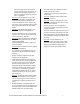
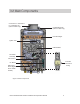
3. About the Water Heater Topics in this section • • • • • Front and Bottom View Main Components Specifications Dimensions Accessories 3.
3.2 Main Components Concentric 3 in. Exhaust/ 5 in.
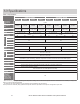
3.3 Specifications Table 2: Specifications Indoor Units RE199i Minimum Gas Consumption Btu/h Maximum Gas Consumption Btu/h RE180i Weight RE199e RE180e RE160e RE140e 199,000 180,000 160,000 140,000 199,000 180,000 160,000 140,000 0.13-9.8 GPM (0.5-37 L/min) 0.13-8.5 GPM (0.5-32 L/min) 0.26-6.6 GPM (1.0-25 L/min) 0.26-5.3 GPM (1.0-20 L/min) 0.13-9.8 GPM (0.5-37 L/min) 0.13-8.5 GPM (0.5-32 L/min) 0.26-6.6 GPM (1.0-25 L/min) 0.26-5.3 GPM (1.0-20 L/min) 42.1 lbs (19.
3.4 Dimensions Measurements: in. (mm) Indoor Models (RE199i, RE180i, RE160i, and RE140i) Front View Side View 10.77 (274) 0.40-1.77 (10-45) 24.64 (626) 22.87 (581) 2.64 (67) 14.05 (357) Figure 4: Indoor Dimensions Outdoor Models (RE199e, RE180e, RE160e, and RE140e) .59 (15) 24.64 (626) 11.13 (283) 10.77 (274) 22.87 (581) 10.67 (271) Side View 2.40 (61) Front View 87 (22) 1.69 (43) 14.
3.4.1 Supply Connections Measurements: in. (mm) Indoor Models (RE199i, RE180i, RE160i, and RE140i) Hot Outlet Gas Cold Inlet H G B C 4.33 (110) Figure 6: Indoor Model Supply Connections 2.71 (69) 1.17 (30) Outdoor Models (RE199e, RE180e, RE160e, and RE140e) Hot Outlet Gas Cold Inlet H B C 4.33 (110) Figure 7: Outdoor Model Supply Connections Table 3: Supply Connections Indoor (wall bracket retracted) G Gas 4.57 (116) C Cold Inlet 2.24 (57) H Hot Outlet 4.6 (117) B Bracket .
3.5 Accessories Numerous optional accessories are available for purchase for your Rinnai Tankless Water Heater. Listed below are some commonly purchased accessories. For a complete list of accessories, visit www.rinnai.us. For questions, or to purchase an accessory, contact your local Rinnai dealer/distributor or Rinnai Customer Care at 1-800-621-9419.
Product DPS/MIS Switch Part #: REU-OPU3 Product Description The Domestic Priority Switch (DPS) function provides domestic hot water priority for combined tankless water heater and air handler use. The Maintenance Indication Switch (MIS) function enables tankless water heater monitoring via programs such as Building Management System (BMS).
4.
DO NOT • DO NOT install the following internal (indoor) water heaters outdoor: RE199i, RE180i, RE160i or RE140i. • DO NOT install the following external (outdoor) water heaters indoor: RE199e, RE180e, RE160e or RE140e. • DO NOT install the water heater in an area where water leakage of the unit or connections will result in damage to the area adjacent to the appliance or to lower floors of the structure.
4.3 Choose an Installation Location When selecting an installation location, you must ensure that all water heater and venting clearances will be met and that the vent length will be within required limits. Consider the installation environment, water quality, and the need for freeze protection. Requirements for the gas line, water lines,and electrical connection can be found in their respective installation sections in this manual. 4.3.
4.3.3 Indoor Water Heaters • DO NOT install the water heater in areas where combustion air might be contaminated with chemicals. • Install the water heater as far away as possible from any air inlet vents. Corrosive fumes, sometimes found in hair/ nail salons, spas, or other industries exposed to toxic fumes, may be released through these vents when not in operation. Chemicals that are corrosive in nature should not be stored or used near the water heater or vent termination.
4.3.5 Freeze Protection The water heater and its water lines must be protected to prevent freezing. Damage due to freezing is not covered by the warranty. When connected to a 120-volt power supply and gas is on, the water heater will not freeze when the outside air temperature is as cold as -22°F (-30°C) for internal (indoor) models or -4°F (-20°C) for external (outdoor) models, when protected from direct wind exposure.
4.3.6 Clearances Indoor (internal) units Outdoor (external) units Top Front Top Side Front Side Bottom Bottom Figure 9: Clearances Table 7: Clearances Indoor units Outdoor units Clearances To Combustibles and Non-Combustibles Location Top Location Clearances To Combustibles and Non-Combustibles 2 in. (51 mm) Top 2 in. (51 mm) 0 in. from vent components Bottom/Ground 12 in. (305 mm) Front (Panel) 0 in. The clearance for servicing is 24 inches in front of the water heater.
4.3.7 Installation Location Checklist Use this checklist to ensure you have selected the correct location for the water heater. □ □ □ □ □ □ □ The water heater is not exposed to corrosive compounds in the air. The water heater location complies with the required clearances. For indoor models, the planned venting will not exceed the maximum length for the number of elbows used. The planned venting termination/air intake location meets the clearances. Indoor air is not being used for combustion.
4.4 Mount the Water Heater to the Wall You Will Need: • Rinnai Tankless Water Heater IMPORTANT The water heater must be installed in an upright position. DO NOT install the water heater upside down or on its side. Supplied by Installer: • Level • Screws for top and bottom bracket installation Use appropriate screws for type of wall construction. 7.09 (180) 6.30 (160) 5.12 (130) 1. Identify the installation location and confirm that the installation will meet all required clearances. 2.
4.4.2 Instructions for Outdoor Models IMPORTANT You Will Need: The water heater must be installed in an upright position. DO NOT install the water heater upside down or on its side. • Rinnai Tankless Water Heater Supplied by Installer: • Level • Screws for top and bottom bracket installation Use appropriate screws for type of wall construction. 5.12 (130) 3.15 (80) Ø.51 (13) Ø .22x .41 (5.5x 10.5) Ø .24x .
4.5 Vent the Water Heater 4.5.1 Guidelines WARNING • This water heater is a direct vent water heater and therefore is certified and listed with the vent system. You must use vent components that are certified and listed with this water heater model. • DO NOT use PVC, CPVC, ABS or galvanized material to vent this appliance. • DO NOT combine vent components from different manufacturers. • The vent system must vent directly to the outside of the building and use outside air for combustion.
4.5.2 Termination Considerations (1.52 m) vertically between terminations at different levels 60 in. Check to determine whether local codes supersede the following clearances: • Avoid termination locations near a dryer vent. • Avoid termination locations near commercial cooking exhaust. • You must install a vent termination at least 12 inches above the ground.
4.5.3 Direct Vent (Indoor): Concentric Pipe Approved Vent Manufacturers and Products Following is a list of vent components and terminations for Direct Vent installations. Install the correct venting for your model according to the venting manufacturer’s instructions and the guidelines below. The information below is correct at time of publication and is subject to change without notice. Contact the vent manufacturer for questions related to the vent system, products, part numbers and instructions.
4.5.4 Direct Vent (Indoor): Termination Clearances TERMINATION TERMINATION X X AIR SUPPLY INLET AIR SUPPLY INLET V VENT TERMINAL V VENT TERMINAL Clearance in Clearance in Ref. Ref.AAalso also applies to to applies anticipated anticipated snow line snow line AREA WHERE TERMINAL AREA WHERE TERMINAL IS NOT PERMITTTED IS NOT PERMITTTED SNOW SNOW I Regulator vent outlet Figure 20: Direct Vent Termination Clearances Table 10 Ref U.S. Installations1 (ANSI Z223.
4.5.5 Maximum Vent Length (indoor models only) 1. Determine the number of 90 degree elbows in the vent system. (Two 45 degree elbows count as one 90 degree elbow.) 2. Refer to the table to find the maximum vent length based on the number of elbows. Table 11 Number of 90° elbows Long (99-A) Short (99- ) 0 21-41 ft (6.4-12.5 m) 0-20 ft (0-6 m) 1 16-35 ft (4.9-10.7 m) 0-15 ft (0-4.6 m) 2 9-29 ft (2.7-8.8 m) 0-9 ft (0-2.8 m) 3 23 ft (7.0 m) 4 17 ft (5.2 m) 5 11 ft (3.4 m) 6 5 ft (1.
Vertical Termination (Condensate collector must be used in all installations) • DO NOT connect the condensate drain pipe directly to the rain sewer. • DO NOT connect the condensate drain line with an air conditioning evaporator coil drain or. • DO NOT connect the condensate drain line to the pressure relief valve/line of the appliance. 3 in. (75 mm) minimum Figure 24 Must Do 3 in. (75 mm) minimum To adjust the condensate collector position: Loosen the 4 screws at the rear bracket 1.
4.5.8 Other than Direct Vent (Outdoor): Termination Clearances TERMINATION X AIR SUPPLY INLET V VENT TERMINAL Clearance in Ref. A also applies to anticipated snow line AREA WHERE TERMINAL IS NOT PERMITTTED SNOW I Regulator vent outlet Figure 26: Outdoor Termination Clearances Table 12 Ref U.S. Installations1 (ANSI Z223.1/NFPA 54) Other than direct vent (Outdoor unit) 12 in.
4.5.9 Termination Clearances for External (Outdoor) Water Heaters 2 in. 36 in. (0.91 m) to ventilated or unventilated soffit or eve vent; or to a deck or porch 12 in. (0.30 m) 60 in. (1.52 m) vertically between terminals 12 in. (0.30 m) from ground anticipated snow line Corner Figure 27 4.5.10 Adjustment for High Altitude Installations Use parameter settings to select the appropriate altitude for your installation. The default setting for the appliance is 0-2,000 ft. (0-610 m), Parameter Setting 2A.
4.6 Connect Water Supply 4.6.1 Guidelines • The piping (including soldering materials) and components connected to this appliance must be approved for use in potable water systems. • Purge the water line to remove all debris and air. Debris will damage the water heater. • The appliance must not be connected to a system that was previously used with a nonpotable water heating appliance. Rinnai Equipment List QTY • Ensure that the water filter on the water heater is clean and installed.
4.7 Install Pressure Relief Valve WARNING Water discharged from the pressure relief valve could cause severe burns instantly or death from scalds. 4.7.1 Guidelines An approved pressure relief valve is required by the American National Standard (ANSI Z21.10.3) for all water heating systems and shall be accessible for servicing.
4.8 Connect the Gas Supply WARNING • A trained and qualified professional must install the gas supply. • Confirm the gas type before connecting. Failure to install correct gas type may result in injury or damage to the unit. • Turn off 120V power supply. • Turn off the gas. • Gas is flammable. DO NOT smoke or provide other ignition sources while working with gas. • DO NOT turn on the water heater or gas until all fumes are gone. 4.8.
4.8.2 Gas Pipe Sizing Reference Tables The gas supply must be capable of handling the entire gas load required at the location. Gas line sizing is based on gas type, the pressure drop in the system, the gas pressure supplied, and gas line type. For gas pipe sizing, refer to the National Fuel Gas Code, ANSI Z223.1/NFPA 54. For some tables, you will need to determine the cubic feet per hour of gas required by dividing the gas input by the heating value of the gas (available from the local gas company).
Propane (Undiluted) Table 16: Pressure Drop 0.5 in. wc Schedule 40 Metallic Pipe Inlet Pressure: 11 in wc Specific Gravity: 1.50 Information in table obtained from NFPA 54, ANSI Z223.1 Nominal Pipe Size (in.
4.9 Connect the Power Supply WARNING • DO NOT use an extension cord or adapter plug with this appliance. • The water heater must be electrically grounded in accordance with local codes and ordinances or, in the absence of local codes, in accordance with the National Electrical Code, ANSI/NFPA No.70. • Indoor water heaters are equipped with a three-prong (grounding) plug for your protection against shock hazard and should be plugged directly into a properly grounded three-prong receptacle.
4.10 Configure Parameter Settings 4.10.1 Instructions WARNING DO NOT adjust parameter settings unless specifically instructed to do so. To adjust the parameters: 1. Locate the PC Board (lower right side of unit). 2. Locate the two push buttons (A and B) on the PC Board. 3. Press the "A" button for 1 second. 4. Use the ▲ (Up) and ▼ (Down) buttons on the controller to select a setting number (see Parameter Settings Table below). A B Figure 31 5.
Table 18: Parameter Settings Table SETTING # SELECTION c 02 SETTING DESCRIPTION Maximum Set Temperature High Altitude Installation 03 Service Soon Disabled 0.
4.11 Recirculation Including recirculation can reduce the amount of time it takes hot water to get to your fixture. This model water heater includes the ability to control a recirculation pump. Two modes are available, Economy and Comfort. • Economy Mode—Cycles the pump less often, using less energy to maintain the circulation loop temperature. • Comfort Mode—Cycles the pump more frequently, ensuring the loop temperature remains higher (but also uses more energy).
4.12 Post-Water Heater Installation Checklist Complete the following checklist when water heater installation is complete. You should be able to answer YES to each question. If you answer NO to any question, installation is not complete. Refer to the applicable section in the Rinnai Tankless Water Heater Installation and Operation Manual for additional information. For assistance, contact your local dealer or distributor, or call Rinnai Customer Care at 1-800-621-9419.
Is the discharge line from the PRV pitched downward and does it terminate 6 in. (152 mm) above the drain? Is the discharge end of the line plain (unthreaded) and a minimum of 3/4 in.
5. Operation Topics in this section • • • • • • Safety Precautions Operating Instructions Control Panel Setting the Temperature Performance Data Diagnostic Codes 5.1 Safety Precautions WARNING If the information in these instructions is not followed exactly, a fire or explosion may result causing property damage, personal injury, or death. • DO NOT store or use gasoline or other flammable vapors and liquids in the vicinity of this or any other appliance.
5.2 Operating Instructions FOR YOUR SAFETY READ BEFORE OPERATING WARNING If you do not follow these instructions exactly, a fire or explosion may result causing property damage, personal injury or loss of life. A. This appliance does not have a pilot. It is equipped with an ignition device which automatically lights the burner. Do not try to light the burner by hand. B. BEFORE OPERATING, smell all around the appliance area for gas.
5.3 Control Panel The water heater includes a controller. For indoor models the controller is integrated into the front cover. For outdoor models, the controller is located inside the front cover. 5.3.1 Setting the Controller to Mute To eliminate the beeps when keys are pressed, press and hold both the (Up) and (Down) buttons at the same time until a beep is heard (approximately 5 seconds). Then, release both buttons. To turn on the beeps, repeat the above steps. Figure 38 5.3.
5.4 Setting the Temperature DANGER Water temperatures over 125°F (52°C) can cause severe burns or scalding resulting in death. Hot water can cause first degree burns with exposure for as little as: • 3 seconds at 140°F (60°C) • 20 seconds at 130°F (54°C) • 8 minutes at 120°F (49°C) Children, disabled, or elderly are at highest risk of being scalded. Feel water before bathing or showering.
5.4.1 Available Temperatures with an Internal Controller The water heater can deliver water at only one temperature setting at a time. The available temperatures are provided below. A temperature lower than 98°F (37°C) can be obtained at the tap by mixing with cold water. To change the temperature scale from Celsius to Fahrenheit or vice versa, press and hold the “On/ Off” button on the controller for 5 seconds while the water heater is OFF.
4. To exit performance data, repeat step 2 above. (Figure 43) 5. When complete, the set temperature appears in the display. Figure 43 Table 23: Performance Data Table # Data Unit 01 Water Flow Rate x0.
5.6 Diagnostic Codes To display diagnostic codes: Turn off the water heater by pressing the “On/Off” button. Press and hold the “On/Off” for 2 seconds and then the (Up) button simultaneously. The last nine maintenance codes display and flash one after the other. To exit diagnostic codes and return the water heater to normal operation, press and hold the “On/Off” button for 2 seconds and then the (Up) button simultaneously. Turn on the water heater by pressing the “On/Off” button.
12 No Flame • • • • • • • • • • • • • • • • • Check that the gas is turned on at the water heater, meter, or cylinder. Check for obstructions in the flue outlet. If the system is propane, make sure that gas is in the tank. Ensure gas line, meter, and/or regulator is sized properly. Ensure gas type and pressure is correct. Bleed all air from gas lines. Ensure proper venting material was installed. Ensure condensation collar was installed properly. Ensure vent length is within limits.
34 Combustion Air Temperature Thermistor Fault • Check for restrictions in air flow around unit and vent terminal. • Check sensor wiring for damage. • Measure resistance of sensor. • Ensure fan blade is tight on motor shaft and is in good condition. • Replace sensor if necessary. 41 51 52 Freeze Protection Thermistor • Check sensor wiring for damage. • Measure resistance of sensor. (See Electrical Diagnostics) • Replace sensor if necessary.
lc Scale Build-up in Heat Exchanger (when checking maintenance code history, "00" is substituted for "LC") • • • FF LC indicates that there is scale build up in the heat exchanger and that the heat exchanger needs to be flushed to prevent damage. Refer to the flushing instructions in the manual. Hard water must be treated to prevent scale build up or damage to the heat exchanger. After flushing, reset LC code as instructed. Please call Rinnai technical department.
6. Maintenance Topics in this section • • • Maintenance Flushing the Heat Exchanger Draining the Water Heater The following maintenance items are required for the proper operation of your water heater. CLEANING It is imperative that control compartments inside the cabinet, burners, and circulating air passageways of the appliance be kept clean. BURNER 6.1 Maintenance This water heater must be inspected annually by a trained and qualified professional.
TEMPERATURE CONTROLLER PRESSURE RELIEF VALVE Use a soft damp cloth to clean the temperature controller. DO NOT use solvents. Operate the pressure relief valve manually once a year. In doing so, it will be necessary to take precautions with regard to the discharge of potentially scalding hot water under pressure. Ensure discharge has a safe place to flow. Contact with your body or other property may cause damage or harm.
UNSATISFACTORY FRONT VIEW Yellow Flame Flame Rod Figure 46 FREEZE PROTECTION Make sure in case of freezing weather that the water heater and its water lines are adequately protected to prevent freezing. Damage due to freezing is not covered by the warranty. Refer to the “Freeze Protection” section (Section 4.3 Choose an Installation Location > Freeze Protection). The water heater may be drained manually.
6.2 Flushing the Heat Exchanger This water heater includes a service indicated/ reminder (Service Soon, SS). When selected in the parameter settings, an SS code will display on the controller indicating that it is time to flush and service the water heater. An LC diagnostic code also indicates the unit is beginning to lime up and must be flushed. Failure to flush the appliance will cause damage to the heat exchanger. Damage caused by lime build-up is not covered by the water heater’s warranty.
6.3 Draining the Water Heater WARNING To avoid burns, wait until the equipment cools down before draining the water. The water in the appliance will remain hot after it is turned off. If the water heater is not going to be used during a period of possible freezing weather, it is recommended that the water inside the water heater be drained. To manually drain the water: 1. Shut off cold water supply and gas supply. 2. Turn off the temperature controller. 3. Disconnect the power to the water heater. 4.
7. Appendices Topics in this section • • • • • Massachusetts State Gas Regulations Wiring Diagram Ladder Diagram Pressure Drop and Water Flow Curves Guidelines for Additional Temperature Controllers 7.1 Massachusetts State Gas Regulations For Gas Models Sold in Massachusetts NOTICE BEFORE INSTALLATION: This direct-vent appliance must be installed by a properly trained licensed professional. If you are not properly trained, you must not install this unit.
Check Valve Rinnai Tankless Water Heater Installation and Operation Manual 59 Tempered water to plumbing fixtures. Must meet temperature requirements of 248 CMR. Min. 2' developed length Type L copper from water heater Hot Water Supply and Return to Heating Coil Water Heater Electronically controlled pump timer. Activates every 6 hours for 60 seconds. Wire to product approved pump. (or built-in pump) Gas Supply System installed with reverse acting aquastat to shutoff fan.
Figure 50 PC Board 7.
7.
7.
7.5 Guidelines for Additional Temperature Controllers All Rinnai Tankless Water Heaters are equipped with an integrated digital temperature controller that allows for a precise water temperature set-point. Additional digital temperature controllers are available as accessories and must be purchased separately (detailed installation steps included with purchase).
8. Warranty What is Covered? The Rinnai Standard Limited Warranty covers any defects in materials or workmanship when the product is installed and operated according to Rinnai written installation instructions, subject to the terms within this Limited Warranty document. This Limited Warranty applies only to products that are installed correctly in the United States. Improper installation may void this Limited Warranty.
What Is Not Covered? This Limited Warranty does not cover any failures or operating difficulties due to the following: • • • • • • • • • • • • • • • • • Accident, abuse, or misuse Alteration of the product or any component part Misapplication of this product Improper installation (such as but not limited to) Product being installed in a corrosive environment Condensate damage Improper venting Incorrect gas type Incorrect gas or water pressure Absence of a drain pan under the appliance Improper maintenance
Rinnai America Corporation 103 International Drive Peachtree City, GA 30269 Tel: Web: 1-800-621-9419 rinnai.us rinnai.