Installation and User Manual RHFE-308 FTR Energysaver Space Heater Important. Read these instructions carefully before attempting installation or use of this appliance. All work must be carried out by competent persons.
CONTENTS Getting to Know your RHFE-308 FTR ………………………………………………………………………3 Remote Control …………………………………………………………………………………………………4 Control Panel Layout …………………………………………………………………………………………5 Features …………………………………………………………………………………………………………6 Safety Points ……………………………………………………………………………………………………8 Operating your new RHFE-308 FTR ………………………………………………………………………10 Setting the Clock ………………………………………………………………………………………………14 Pre-heat ………………………………………………………………………………………………………17 Override Function ……………………………………………………………………………………………1
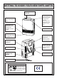
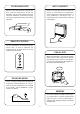
GETTING TO KNOW YOUR NEW RHFE-308FTR REMOTE CONTROL BRACKET CONTROL PANEL Concealed panel with clock, room and preset temperature selection. Time, temperature and appliance error codes are shown here. LOUVRE Warm air discharge duct. HUMIDIFIER TRAY Built into the warm air discharge duct. Humidifies the warm air flow. ON/OFF SWITCH BOTTOM TRIM Pulls off to allow filling of humidifier tray. AIR FILTER Helps to protect the interior of the appliance and fan from dust particles.
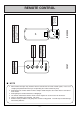
Power source for operating remote control. REVERSE R2032 C OPEN FRONT Increases or decreases the temperature setting. TEMPERATURE ADJUSTMENT Stops heater manually. OFF ON Operates the heater manually. ON BUTTON OFF BUTTON TO REPLACE BATTERY Simply open the back of the remote control and replace Lithium battery.
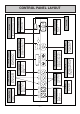
–5– Selects energy saving function. ECONOMY Temporarily changes operation from ON to OFF or OFF to ON, until next programmed setting is reached. OVERRIDE Selects clock and/or Timers for adjusting or programming. SET TIMES REMOTE CONTROL RECEIVER Main switch for turning ON/OFF. Increases or decreases the temperature setting as well as changing hours or minutes. ON / OFF ON Filter Selects operating mode for Timer 1 or 2. off Locks all controls when pressed.
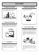
FEATURES FORCED FLUE SYSTEM PUSH BUTTON IGNITION Air for combustion is taken from outside the room and the flue products are exhausted outside, keeping the room air clean. Only one touch of the ON/OFF switch is required to operate the heater. EXHAUST ONE TOUCH AIR INLET WARM AIR DISCHARGE Warm air flows from the bottom of the appliance through the louvres, assisting in even heat distribution. An integral humidifier tray is built into the warm air discharge duct.
FILTER INDICATOR AUTO COMFORT When the fan filter becomes covered with dust and the temperature inside the appliance rises, the filter indicator will flash. The filter should be vacuumed at regular intervals to avoid unnecessary strain on the appliance. Ensures that the flow of warm air from the louvres is maintained at a comfortable volume during the warm-up period by a 8 step modulating convection fan, in conjunction with the thermostat, reducing cool draughts.
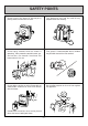
SAFETY POINTS Do not restrict the warm air discharge by placing articles in front of the heater. This appliance must not be used for any purpose other than heating. Do not spray aerosols whilst the heater is operating. Most aerosols contain butane gas, and can be a fire hazard if used near this heater when it is in use. Flue guard is recommended where children may be able to touch the flue terminal. Do not allow curtains or other flammable or combustible materials to come into contact with the heater.
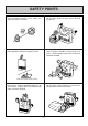
SAFETY POINTS Keep flammable materials, trees, shrubs, etc, away from the flue terminal. Do not allow anyone to post articles through the louvres. GAS Gasoline LPGAS Filter should be cleaned at regular intervals. Young children should be supervised at all times. Hand or body contact with the louvres should be avoided. Clean with vacuum cleaner, weekly. Do not allow young children or the infirm to sleep directly in front of the heater. Do not place articles containing liquids on top of the heater.
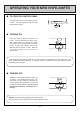
OPERATING YOUR NEW RHFE-308FTR ■ TO OPEN THE CONTROL PANEL Lift lightly in the centre of the lid where there is a catch. The control panel lid will then drop backward to an angle. LIFT ■ TURNING ON Press the ON/OFF button to operate the heater. The ON indicator will glow green. After approximately 20 seconds the spark generator will be heard before the burner ignites and the ON indicator glows red, indicating that the burner is alight. Warm air can be felt coming from the louvres 15 seconds later.
■ ROOM TEMPERATURE ADJUSTMENT The room temperature and pre-set temperatures can only be displayed and adjusted when the heater is running. 1 Press the “ ” button to increase the temperature setting or “ ” button to decrease the temperature setting.
■ CHILD LOCK The Child lock will help to prevent accidental operation as well as small children from altering the controls. 1 To operate the Child lock simply press the Child Lock button. The function is activated immediately and the Child lock indicator will glow. Child Lock Economy Timer 1 Timer 2 Override Child Lock Economy Timer 1 Timer 2 Override 2 To deactivate the Child lock simply press the Child Lock button for 2 seconds and the Child lock indicator will go out.
■ FAN FILTER To protect the room air fan from dust particles or lint, a filter is situated at the rear of the appliance. When this filter becomes blocked, the filter indicator will flash to indicate that it should be cleaned. Clean the filter weekly during the heating season to avoid unnecessary strain on the appliance. Do not remove filter when appliance is operating. When the filter requires cleaning, clean filter before using the appliance, or whilst the appliance is not operating.
SETTING THE CLOCK When the appliance is first plugged in and then turned on, the Digital Display will show As an example, let’s set the clock to 10:35 am. . TIMER/CLOCK SET INDICATOR DIGITAL DISPLAY ON-OFF SWITCH INDICATOR TIMER/TEMP ADJUSTMENT ON-OFF SWITCH TIMER/CLOCK SET OPEN THE CONTROL PANEL - SEE PAGE 10. 1 When the appliance is first plugged in or after a power failure, the Digital Display will show .
PROGRAMMING THE ON/OFF TIMER(S) Before programming the Timers you must ensure that the clock has been set to the correct time. See page 14. As an example let’s programme Timer 1 to heat the room by 7:10 AM and finish at 9:00 AM. 1 Press the Set Times button twice. The Digital Display will show AM 6:00. Timer 1 indicator will flash.
OPERATING THE TIMER(S) Before operating the Timer(s), the clock time must be correct, and a starting time and finishing time for the Timer(s) must be programmed. See pages 14 and 15. The two Timers operate in the same way. This heater does not commence operation at the programmed starting time. It will attempt to heat a room by the programmed starting time. See Pre-heat page 17, for further explanation.
PRE-HEAT 1 This function operates automatically in conjunction with either of the Timers. When a Timer is selected, the heater may operate anywhere within an hour prior to the programmed starting time of the Timer. The Pre-heat function will heat a room to the pre-set temperature by the programmed On Time. This function is called Pre-heat due to the way it operates. The room temperature is sensed one hour before reaching the programmed time of either Timer.
OVERRIDE FUNCTION This function is intended to be used to manually override the current operation of the heater, For example; if the heater is in standby mode (i.e. between finishing time and starting time of a Timer), and the Override button is selected, then the heater will begin to operate, and heat the room. 1 To operate the Override simply press the Override button. The Override indicator will flash.
CARING FOR YOUR NEW RHFE-308FTR This appliance is controlled by a micro computer. If there is something wrong with the appliance then it will stop, as it is protected by the following safety devices. Ignition Safety Device Burner Safety Device Overheat Safety Device Power Failure Safety Device Power Surge Safety Device Fan Delay Safety Device Your RHFE-308FTR requires very little maintenance, simply clean the rear fan filter once a week and wipe the outer case and louvre section with a damp cloth.
PRE-SERVICE CHECK Before asking for a service call please check the following points. These points are part of the normal operation of the unit. ■ At Ignition: Heater does not operate. R Is the heater plugged in? Have the fuses or breaker blown at the switch board? Is there a power failure? Is the air filter blocked? Is anything blocking the outlet for the hot air? Is the flue blocked? Are Timers set? Clear Timers and operate again. Warm air does not flow when the burner lights.
ERROR MESSAGES The Rinnai RHFE-308FTR has the ability to check its own operation continuously. If a fault occurs, an error message will flash on the Digital Display of the control panel. This assists will diagnosing the fault, and may enable you to overcome a problem without a service call. Please quote the code when enquiring about service. Code Displayed Fault Remedy Ignition Failure Check gas in ON. Service call if repeated Flame Failure Check gas in ON.
INSTALLATION INSTRUCTIONS Important Safety Instructions 1. Gas Safety (Installation & Use) Regulations 1998 are the ‘Rules in Force’. In your own interest and that of safety, it is law that all gas appliances shall be installed by competent persons in accordance with the above regulations. Failure to install appliances correctly could lead to prosecution. Other persons should NOT attempt to install this equipment. 2. Unpack the appliance and check it carefully.
INSTALLATION INSTRUCTIONS Specification Input: Ignition: Flue: Gas Control: Electrical Supply: 3.4kW Burner: Stainless Steel Bunsen Type Continuous Spark Gas Inlet: 1/2 in. BSP Forced Flue (Components supplied separately.) Rinnai Electronic Modulating Control 230V, 50Hz. This unit has a supply lead and 3 pin plug. Remove parts from carton and check that all parts shown below are included in the installation kit.
LOCATION When positioning the heater the main points governing the location are: This heater is not designed to be built in. 1. Flueing 2. Warm air distribution This heater must not be installed where curtains or other combustible materials could come into contact with it. In some cases curtains may need restraining. See diagram for other recommended clearances. 300 The flue is not designed to be positioned under floors, or below the level of the heater.
LOCATION Do not flue into natural draught flues or fireplaces, this unit can only be used with one of the six types of Rinnai flue kits. Do not flue unit into other rooms. Flue terminal must be outside. STANDARD INSTALLATION OF FLUE MANIFOLD. Diagram below shows minimum clearances and distances from obstructions. Also check local regulations.
LOCATION Do not install the heater in an unusually dusty area. FLUE MANIFOLD POSITION Important The centre of the hole for the flue manifold must only be drilled in the position indicated on the diagram below. Drill Hole 80mmφ thru wall 115 677 Flue Elbow 265 • Use a flue guard if the terminal is easily accessible to children. • Check local regulations. • Guards are available as an optional extra. 217 Guard All measurements are taken from the extremities of the appliance.
INSTALLING THE FLUE General. The flue must be installed in accordance with: Manufacturers Installation Instructions British Standards including BS 5440 and BS EN 1319:1999 Gas Safety (Installation and Use) Regulations IGE/UP/10 Part 1 Edition 2. Building Regulation J The flue must be installed by a competent, authorised person. It is the installer’s responsibility to ensure that the unit has been installed to all current requirements.
POSITIONING THE FLUE TERMINAL Q I Q Q P F D,E G Dimension N O C M B L N H A I H M J Terminal Position K Distance A Directly below an opening, air brick, opening windows, etc. 300mm B Above an opening, air brick, opening window, etc. 300mm C Horizontally to an opening, air brick, opening window, etc. 300mm D Below gutters, soil pipes or drain pipes. 75mm E Below eaves. 200mm F Below balconies or car port roof. 200mm G From a vertical drain pipe or soil pipe.
SLEEVE AND MANIFOLD INSTALLATION METHOD FOR STANDARD WALLS 1. Dis-assemble Manifold from Sleeve. The flue consists of 3 parts, sleeve, inside connectors and tube, outside terminal; (disassemble by pulling hard on outside terminal and inner connections, then pull sleeve off outer terminal). Connections Sleeve Terminal 2. Adjustment of Sleeve Length. Measure wall thickness through previously drilled 80mm hole. End of sleeve should protrude 5-10mm from outside wall.
SLEEVE AND MANIFOLD INSTALLATION METHOD FOR STANDARD WALLS 5. Check rubber seal is in place on terminal. Terminal seal (Add "weather board" seal here) * For weather board walls, add spare rubber seal provided to compensate for weatherboard angle. 6. Installation of Terminal "TOP" mark "A" Label From outside, insert terminal into sleeve with the “A” mark at the top. Left hand side fixing tie is marked “LEFT” (from inside). Fixing Tie Terminal Cut (leave 20mm free) 7.
FITTING UNIT AIR INLET HOSE 2. Locking clamp a Hook Elbow b Locking Clamp Manifold Fit the locking clamp over the connection between the flue elbow and the manifold. Engage the hook and rotate it until it snaps against the body of the clamp. Attach the Air Inlet Hose to the flue manifold on either inlet position a or b. The unused inlet is plugged with the rubber cap supplied on the manifold. 3.
FORCED FLUE HEATER EXTENSION KITS EXTENSION KIT PARTS AND INSTALLATION GUIDE FOT - 155 0.5m EXTENSION KIT FOT - 156 1.0m EXTENSION KIT FOT - 157 2.0m EXTENSION KIT FOT - 158 BENT ELBOW KIT FOT - 160 LONG FLEX TUBE 600 KIT • This extension set is to be used for installations requiring extra distance. MAXIMUM FLUE LENGTH 4.
FLUE EXTENSION KITS INSTALLING AN EXTENSION KIT FOR THE RHFE-308 FTR Installing an extension kit requires construction of an air line and the flue line. The air line is connected between the Air Supply Elbow at the rear of the heater and the air inlet port on the Flue Pipe. Similarly, the flue line is connected between the joint pipe at the rear of the heater and the flue port on the flue pipe. Caution: Check to see there is no debris in the pipe or hose. HOW TO INSTALL Example.
FLUE EXTENSION KITS 1. How to connect the flue pipes. To connect the rigid flue pipes fit the male end into the female end and clamp with pipe stopper A to prevent slipping. The flue pipe can be telescoped to the required length: DO NOT CUT IT. Male end Female end Exhaust pipe Exhaust pipe Connect bent pipe Fit inside Male end Pipe stopper B Pipe stopper A Male end Female end Fit inside Female end Pipe stopper B Pipe stopper A 2. How to connect air intake hose.
FLUE EXTENSION KITS ■ CAUTIONS 1. Maximum extendable length FOR BEST ROOM AIR HUMIDITY, KEEP WATER IN THE HUMIDIFIER TRAY. 2. To prevent water condensation Condensed water may accumulate here, and cause a blockage preventing combustion. • 7.0 Metres less 1m per bend to a max 3 bends. • The bend where the hose and pipes leave the body is not counted. • The air intake hose should run along the exhaust pipe.
CONVERSION The following procedure must be followed to convert the unit from Nat. Gas to LPG. 1. Hold both ends of the bottom cover. (Undercover ass’y) and pull toward you to remove the cover. Cover is snapped into place. (See fig #1) 2. Remove the 7 screws that secure the front panel and the louver assembly and remove panel from the unit. Pull the panel out at the bottom about 100mm and lift up over clips that hold it in place at the unit’s top.
CONNECTING GAS AND ELECTRICAL SERVICES 1. GAS CONNECTION. Purge any air or swarf from the gas line. Connect up the appliance to the gas supply using a union service cock to facilitate servicing. Inlet connection size Gas (1/2 inch male BSP) Check gas soundness using leak detection fluid, not naked flame. Connection can be easily reached from right hand side rear of appliance. Remove bottom trim (pulls off). Remove louvres (6 screws) and front panel. 2. ELECTRICAL CONNECTION.
TESTING Testing Unit Fault - Finding Procedure Purge air from gas line. Refer to pipe sizing chart if in doubt about the size of the gas line. Connection can easily be reached from the top, rear or the unit. Check for leaks using soapy water or leak detection spray after turning gas on. If unable to get the unit to operate correctly, contact Rinnai UK. Do not use this heater if any part has been under water.
GAS PRESSURE SETTING The working gas pressure on the water heater is electronically controlled and factory set. Under normal circumstances it does not require adjustment during installation. Perform this procedure only if the unit is not operating correctly and all other possible causes for incorrect operation have been eliminated, or you have converted the Gas Type. Contact Rinnai UK before attempting to alter the gas pressure. Turn the appliance to the OFF position. 1.
GAS PRESSURE SETTING 1. With your manometer gauge zeroed and connected to both pressure taps, press the On/Off button and operate appliance. 2. Press the SW1 test switch. 78 or 7≡ will be displayed on the incidator LED. 3. Press the SW1 switch again to put the appliance in Low pressure mode. PL will appear on the LED display. Set Temp RoomTemp Temp Control 4. Adjust the low pressure using the UP and DOWN arrows until the pressure differential shown on the manometer is: Gas Pressure Nat.
FITTING TOP SPACER AND WALL CLIP Once Commissioning is complete the last thing to do is fix the top spacer. • INSTRUCT CUSTOMER ON USE OF HEATER When you are satisfied that the appliance is operating correctly explain operation of heater to the customer. 1. Fit the spacer bracket to the top spacer. Fault-Finding Procedure If you are unable to get the heater to operate correctly contact Rinnai UK directly. Some items are not covered by the manufacturer’s warranty.
BLOCK DIAGRAM Mark MS R, TH TF F ER TR PARTS NAME MAIN SWITCH THERMISTOR THERMAL FUSE FUSE ELECTRODE TRANSFORMER Mark FR RC CF OH, TH OHS1, 2 FM PARTS NAME FLAME ROD REMOTE CONTROLLER CONVECTION FAN OVER HEAT THERMISTOR OVER HEAT SWITCH 1, 2 CONVECTION FAN MOTOR – 42 – Mark SP SV1, 2 BL RCR TB PS POV PARTS NAME SPARKER MAIN SOLENOID VALVE 1, 2 COMBUSTION FAN MOTOR REMOTE CONTROL RECEIVER TERMINAL BLOCK PRESSURE SENSOR MODULATING SOLENOID VALVE
WIRING DIAGRAM RHFE-308FTR AC230V TB r r 3 TR2 bk bk PS M r bk w CODE bk bl gr gr / y pk r w y gy or br lb – 43 – COLOUR black blue green green/yellow pink red white yellow grey orange brown light blue
DIMENSIONS (mm) WALL CLIP 260 165 85 GAS CONNECTION 335 117 335 618 677 121 426 25 – 44 –
FLUE POSITION THROUGH WALL 88 WALL OPENING POSITION (CENTRE OF FLUE) 109.5 676.5 121 83 616 15 264.5 64 R1 296.
SPECIFICATION Model ........................................................................................................................................ RHFE-308 FTR Installation .................................................................................................................. Internal location only Fuel ............................................................................................................................... Natural Gas or LPG** Control ............................
NOTES – 47 –
SERVICE CONTACT UK LTD. 9 Christleton Court Manor Park Runcorn Cheshire WA7 1ST Tel. 01928 531870 Fax. 01928 531880 E-mail. info@rinnaiuk.com Web. www.rinnaiuk.com 308F-1092 2007.