WARNING AVERTISSEMENT If the information in these instructions is not followed exactly, a fire or explosion may result causing property damage, personal injury, or death. Assurezvous de bien suivre les instructions données dans cette notice pour réduire au minimum le risque d’incendie ou d’explosion ou pour éviter tout dommage matériel, toute blessure ou la mort. • It is recommended that a trained and qualified professional who has attended a Rinnai training class complete your installation.
For installations in Canada, the conversion shall be carried out in accordance with the requirements of the provincial authorities having jurisdiction and in accordance with the requirements of the CSAB149.1, Natural Gas and Propane Installation Code. Si l’appareil est installé au Canada, la conversion doit être effectuée conformément aux exigences des autorités provinciales compétentes et conformément aux exigences de la norme CSA-B149.1, Code d’installation du gaz naturel et du propane.
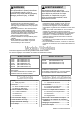
IMPORTANT The French manual continues on page 15. (Le manuel en français continue à la page 15.) IMPORTANT This manual provides instructions on converting the Rinnai indoor tankless water heater (applicable models1) to an outdoor installation. For detailed information on the water heater, such as specifications, installation instructions, and operating information, refer to the “Tankless Water Heater Installation and Operation Manual” supplied with the unit, or located online at www.rinnai.us.
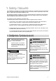
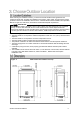
When selecting an installation location, you must ensure that all water heater guidelines and clearances will be met. Consider the installation environment, water quality, and the need for freeze protection. Refer to the installation sections in the “Tankless Water Heater Installation and Operation Manual” for gas line, water lines, electrical and condensate disposal requirements.
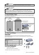
Clearances for Outdoor Installations Clearances to Combustibles and Non-combustibles Location Top 2 in. (51 mm) Bottom/Ground 12 in. (305 mm) Figure 3 Top Outdoor Vent Cap Exhaust Outlet 0 in. Clearance for servicing is 24 in. (610 mm) in front of water heater. Front Front Do not block the exhaust outlet opening. Back 0 in. Sides (Left and Right) 2 in. (51 mm) Front Exhaust 24 in.
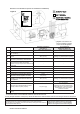
Non-Direct Vent Clearances (Room Air and Outdoor Installations) Figure 5 TERMINATION V SNOW I Regulator vent outlet. In the event no regulator is present, H and I can be disregarded. Ref Canadian Installations1 (CSA B149.1) Other than direct vent (Outdoor unit and/or Room Air) Description A Clearance above grade, veranda, porch, deck, or balcony 12 in. (30 cm) 12 in. (30 cm) B Clearance to window or door that may be opened 36 in. (91 cm) 4 ft (1.
WARNING • Do not use an extension cord or adapter plug with this water heater. • The water heater must be electrically grounded in accordance with local codes and ordinances or, in the absence of local codes, in accordance with the National Electrical Code, ANSI/ NFPA No. 70. • This water heater is equipped with a three-prong (grounding) plug for your protection against shock hazard and should be plugged directly into a properly grounded three-prong receptacle.
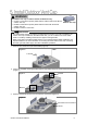
WARNING The outdoor vent cap is used for outdoor installations only. • DO NOT install internal (indoor) water heaters outdoors without the Rinnai Outdoor Vent Cap outdoor vent cap. • DO NOT install internal (indoor) water heaters indoors with the Rinnai outdoor vent cap. • DO NOT install in a recess box. IMPORTANT • The water heater must be mounted to the wall before the outdoor vent cap is installed.
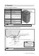
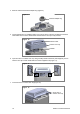
4. Remove and discard exhaust adapter ring (Figure 9). Figure 9 Exhaust adapter ring 5. Inspect gaskets prior to installing outdoor vent cap as shown in Figure 10. Make sure exhaust outlet faces the front of the water heater and the outdoor vent cap is fully inserted. Figure 10 Exhaust outlet Outdoor vent cap Gaskets 6. Open front door of outdoor vent cap. Using a Phillips head screwdriver (field-supplied), secure outdoor vent cap to water heater with two screws supplied in kit (Figure 11).
This tankless water heater is set up for natural gas and indoor installations as default. When power is connected for the first time, you need to choose the correct gas type and outdoor setting. 2. Supply power to the tankless water heater for the first time. The controller displays “SEt” and the “Priority” button LED light on the controller is blinking.
7. Follow the steps in the Rinnai Central™ app to change your tankless water heater settings. 8. When settings are complete, the controller display will appear blank (the display will turn off). 9. Tankless water heater setup is complete. Press the “On/Off” button to turn on the tankless water heater. 1. Supply power to the tankless water heater for the first time. The controller displays “SEt” and the “Priority” button LED light on the controller is blinking.
3(B). If using propane gas: Press the up or down arrow button. The controller displays “LPG” (Liquid Propane Gas). Press the “On/Off” button to confirm propane gas. Then, proceed to step 4. 6. The controller displays “nG” or “LPG,” and “In” or “Out” alternatively while the “Priority” button LED light is flashing. The controller is showing the current gas setting and indoor/outdoor setting.
IMPORTANT The controller is automatically locked after 30 minutes of inactivity. To unlock the controller: 1. Press and hold down the “Priority” button. 2. While holding down the “Priority” button, press the up arrow button until a beep is heard (approximately 5 seconds). Then, release both buttons at the same time. Note: The key symbol on the controller will not illuminate, indicating the controller is unlocked.
IMPORTANT The French manual continues below. (Le manuel français se poursuit ci-après.) IMPORTANT Le présent manuel fournit les instructions nécessaires à la conversion de chauffe-eau instantanés en intérieur Rinnai (modèles concernés1) pour permettre une installation en extérieur.
Lorsqu’il faut choisir un emplacement pour l’installation, s’assurer que toutes les consignes relatives au chauffe -eau et tous les dégagements sont respectés. Tenir compte de l’environnement, de la qualité de l’eau et des besoins éventuels concernant la protection contre le gel.
Dégagements pour les installations en extérieur Dégagement par rapport aux matériaux combustibles et non combustibles Emplacement Haut 51 mm (2 po) Bas/sol 305 mm (12 po) Figure 3 Chapeau de ventilation extérieure Évacuation des fumées 0 cm (0 po) Le dégagement prévu pour l’entretien est de 610 mm (24 po) en face du chauffe-eau. Avant Côté Ne pas bloquer l’évacuation des gaz de combustion.
Dégagements en cas de ventilation indirecte (air ambiant ou installations en extérieur) Figure 5 EXTRÉMITÉ X Aperçu des angles intérieurs ENTRÉE D’AIR V TERMINAISON D’ÉVACUATION Les dégagements relatifs à la Réf. A s’appliquent également à la hauteur de neige prévue. ZONE OÙ AUCUN TERMINAL N’EST AUTORISÉ NEIGE Fermé (fixe) Actionnable Fermé (fixe) I Extrémité d’évacuation du régulateur. Si aucun régulateur n’est présent, les points H et I peuvent être ignorés.
AVERTISSEMENT • Ne pas utiliser de rallonge ou d’adaptateur avec ce chauffe-eau. • Une fois installé, le chauffe-eau doit être mis à la terre conformément aux codes locaux ou, en l’absence de codes locaux, au National Electrical Code, ANSI/NFPA No. 70. • Ce chauffe-eau est équipé d’un connecteur tripolaire (fil de terre) pour vous protéger contre les risques d’électrocution et doit être branché directement dans une prise femelle tripolaire adéquate.
AVERTISSEMENT Le chapeau de ventilation extérieure est utilisé uniquement dans les installations en extérieur. • NE PAS installer de chauffe-eau prévu pour l’intérieur à l’extérieur sans le • • chapeau de ventilation extérieure Rinnai. NE PAS installer de chauffe-eau prévu pour l’intérieur à l’intérieur avec le chapeau de ventilation extérieure Rinnai. NE PAS installer dans un boîtier encastrable.
4. Retirer et mettre au rebut la bague adaptatrice d’évacuation (figure 9). Figure 9 Bague adaptatrice d’évacuation 5. Inspecter les joints avant d’installer le chapeau de ventilation extérieure, comme l’illustre la figure 10. S’assurer que la sortie d’évacuation est orientée vers l’avant du chauffe-eau et que le chapeau de ventilation extérieure est inséré à fond. Figure 10 Évacuation des fumées Chapeau de ventilation extérieure Joints 6. Ouvrir le capot avant du chapeau de ventilation extérieure.
Ce chauffe-eau instantané est conçu par défaut pour le gaz naturel et les installations en intérieur. À la première mise sous tension de l’appareil, sélectionner le type de gaz approprié ainsi que le réglage extérieur. 2. À la mise route initiale de l’alimentation électrique du chauffe-eau, le contrôleur affiche « SEt » et le voyant LED de la touche Priority (Priorité) du contrôleur se met à clignoter.
7. Suivre les instructions de l’application Rinnai Central™ pour modifier les réglages du chauffeeau instantané. 8. Une fois les réglages terminés, l’écran du contrôleur est vierge (le contrôleur s’éteint). 9. L’installation du chauffe-eau instantané est terminée. Appuyer sur la touche « ON/ OFF » (Marche/Arrêt) pour mettre le chauffeeau instantané en marche. 1. SEt Touche « ON/ OFF » (Marche/ Arrêt) IMPORTANT Le contrôleur est automatiquement verrouillé après 30 minutes d’inactivité.
3(B). Pour du propane: Appuyer sur la touche fléchée haut ou bas. Le contrôleur affiche « LPG » (gaz propane liquide). 6. Appuyer sur la touche « ON/OFF » (Marche/ Arrêt) pour valider l’utilisation de gaz propane. Passer ensuite à l’étape 4. LPG Par exemple, si le contrôleur affiche « nG » et « Out », en alternance, cela indique que le chauffe-eau est réglé pour du gaz naturel et l’installation est en extérieur. 7.
IMPORTANT Le contrôleur est automatiquement verrouillé après 30 minutes d’inactivité. Déverrouiller le contrôleur: 1. maintenir enfoncée la touche « Priority » (Priorité). 2. Tout en maintenant la touche « Priority » (Priorité) enfoncée, appuyer sur la touche fléchée vers le haut jusqu’à ce qu’un bip se fasse entendre (environ 5 secondes). Ensuite, relâcher simultanément les deux touches. Remarque: La clé présente sur le contrôleur ne s’allume pas, ce qui indique que le contrôleur est déverrouillé.
Outdoor Conversion Manual
Outdoor Conversion Manual 27