DE GB FR ES Bedienungsanleitung User’s manual Manuel d’utilisation Manual de usuario SWING pro JAZZ pro HIPHOP pro
DE Inhaltsverzeichnis 1 2 3 4 5 6 7 8 9 10 11 12 13 14 15 16 17 18 19 20 21 22 23 24 25 26 27 28 29 30 31 32 Gewährleistung................................................................................................................................................................ 6 Kontaktadresse der Vertriebsgesellschaft ....................................................................................................................... 6 Vorwort ............................................
GB Contents 33 34 35 36 37 38 39 40 41 42 43 44 45 46 47 48 49 50 51 52 53 54 55 56 57 58 59 60 61 62 63 64 Warranty ........................................................................................................................................................................ 26 Distributor’s address ...................................................................................................................................................... 26 General Information ................
FR Contents 65 66 67 68 69 70 71 72 73 74 75 76 77 78 79 80 81 82 83 84 85 86 87 88 89 90 91 92 93 94 95 Garantie ......................................................................................................................................................................... 46 Adresse du Distributeur ................................................................................................................................................. 46 Informations générales ..................
ES Índice 96 Garantía......................................................................................................................................................................... 66 97 Dirección del distribuidor ............................................................................................................................................... 66 98 Información General ......................................................................................................................
1 Gewährleistung RIPEnergy AG ist nicht Hersteller der angebotenen Produkte. Alle technischen Informationen, Daten und Abmessungen basieren auf den Angaben der betreffenden Hersteller und sind keine Zusicherungen der RIPEnergy AG für spezifische Eigenschaften. Für allfällige Druck- und Übermittlungsfehler kann keine Haftung übernommen werden. Bei Arbeiten, die nicht in Übereinstimmung mit den gültigen Richtlinien, Anweisungen und Spezifikationen erfolgen, können erhebliche Schäden entstehen.
5 Haftungs-Ausschluss Die Einhaltung der jeweils gültigen lokalen Normen und Sicherheitsrichtlinien, aller Montage- und Installationsvorschriften, wie auch die Kontrolle des sachgemässen Betriebes liegen beim Installateur resp. Kunden. RIPEnergy AG kann deshalb keinerlei Verantwortung, Haftung oder Garantie übernehmen, falls das Gerät durch fehlerhafte Montage resp. Installation oder bei unsachgemässer Verwendung zerstört wird. Ebenso ausgeschlossen sind Forderungen infolge von Personenschäden.
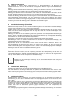
10 Blockschaltbild 11 Sicherheits-Hinweise 11.1 Generelle Hinweise Informieren Sie sich bei den zuständigen Stellen über die geltenden Installations-/Betriebsvorschriften! Alle Arbeiten am Gerät (dessen Montage, elektrische Installation und Inbetriebnahme) müssen gemäss den nationalen Bestimmungen und den örtlichen Vorschriften ausgeführt werden.
12 Problemlösungen Warnung - Das Gerät nie öffnen! Versuchen sie nie das Gerät selber zu reparieren. Elektrische Schläge, ernsthafte Verletzungen oder Feuer könnten die Folgen sein. Keine Funktion Überprüfen Sie die LED-Anzeige um einen Hinweis auf die mögliche Ursache zu finden. Entsprechend der Fehlermeldung, wie weiter unten beschrieben vorgehen. Überprüfen Sie die Verkabelung auf korrekten und festen Sitz. Überprüfen Sie die Batterie-Sicherungen und die Sicherung im AC-Verteiler.
15 Planung, Montage In diesem Abschnitt erfahren Sie, was es alles braucht um eine korrekte Installation durchführen zu können und wie Sie dabei vorgehen müssen. Vergewissern Sie sich, dass Sie alle vorhergenannten Sicherheits-Hinweise kennen und stellen Sie sicher, dass alle Schutzmassnahmen eingehalten werden. 15.
16 Inbetriebnahme SWING pro Serie 16.1 Elektrischer Anschluss DC-Seite Der Schalter auf der Frontseite des Gerätes muss auf OFF stehen. Direkt an der Batterie muss eine Hochleistung Schmelz-Sicherung oder ein entsprechender Schütz eingebaut werden. (Ausnahme Swing pro 200-12-230). DC - Strom gemäss Datenblatt. Ist diese Sicherung nicht vorhanden, so kann dies im Falle eines Kurzschlusses der beiden Batterie-Kabel zu einem Brand führen.
17 Fernsteuerung (Remote Anschluss) nur Swing pro 350 Das Kabel des optional erhältlichen Fernsteuerungsmoduls wird auf der Inverter Rückseite eingesteckt. Damit lässt sich das Gerät ferngesteuert Ein- und Ausschalten. Der Schalter auf der Frontplatte des Inverters muss auf „ON“ gestellt werden. Remote Anschluss 18 Betrieb Der Inverter wird über den Schalter an der Vorderseite des Gerätes bedient. Einschalten Schalten Sie den Schalter auf „ON“, es ertönen drei kurze akustische Signale.
20 Technische Daten 200VA 350VA 13/85 V 1.
21 Inbetriebnahme JAZZ pro Serie 21.1 Elektrischer Anschluss DC-Seite Der Schalter auf der Frontseite des Gerätes muss auf OFF stehen. Vorsicht! Die konfektionierten Kabel zuerst am Inverter anschliessen. Erst in einem zweiten Schritt mit der Batterie verbinden! Immer zuerst das Massekabel mit der Batterie verbinden! Direkt an der Batterie muss eine Hochleistung Schmelz-Sicherung oder ein entsprechender Schütz eingebaut werden. DC - Strom gemäss nachfolgender Tabelle.
22 Fernsteuerung und Fernüberwachung (Remote Anschluss) Als Option ist eine die Bedieneinheit erhältlich, welche das ferngesteuerte Bedienen und Überwachen des Inverters ermöglichen. Der Anschluss der Bedieneinheit erfolgt über den Stecker „RS232C“ auf der Rückseite des Inverters. Der Inverter erkennt die angeschlossene Fernsteuerung automatisch. Wir empfehlen die Option: Bedieneinheit „Remote Panel pro Serie“. Das Anschlusskabel ist im Lieferumfang der Bedieneinheit enthalten.
24 Betrieb Der Inverter wird über den Schalter an der Vorderseite des Gerätes bedient. Einschalten Schalten Sie den Schalter auf „ON“; es ertönen drei kurze akustische Signale. Danach ertönt ein längerer Alarmton und die AC Ausgangsspannung erscheint auf der Anzeige. Der Inverter ist Betriebsbereit. Ausschalten Schalten Sie den Schalter auf „OFF“.
VAC Bereich 100120 Genauigkeit +/- 1% AMP WATT VDC 200240 0-20 0-2KW 10-16 20-32 +/- 1% +/- 1% +/- 3% +/- 2% +/- 2% TEMP Hz 42-62 0-120°C 50 +/- 2% +/- 1% +/- 0.01 +/- 0.01 60 25.7 Überspannungsschutzanzeige: (OVP) Bei zu hoher Eingangsspannung (Batteriespannung) schaltet der Inverter automatisch aus. Die Anzeige OVP erscheint im Display. Vorsicht! Der Inverter schaltet automatisch wieder ein, wenn die Spannung wieder im zulässigen Bereich liegt. 25.
26 Technische Daten JAZZ pro 700 JAZZ pro 1000 18/85 V 1.
27 Inbetriebnahme HIPHOP pro Serie 27.1 Elektrischer Anschluss DC-Seite Der Schalter auf der Frontseite des Gerätes muss auf OFF stehen. Vorsicht! Die konfektionierten Kabel zuerst am Inverter anschliessen. Erst in einem zweiten Schritt mit der Batterie verbinden! Immer zuerst das Massekabel mit der Batterie verbinden! Direkt an der Batterie muss eine Hochleistung Schmelz-Sicherung oder ein entsprechender Schütz eingebaut werden. DC - Strom gemäss nachfolgender Tabelle.
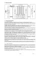
27.2 Elektrischer Anschluss AC-Seite HIPHOP pro 1500 & HIPHOP pro 2000 Für den Anschluss auf der AC-Seite benützen Sie den mitgelieferten Stecker. HIPHOP pro 3000 Für den Anschluss auf der ACSeite öffnen Sie die Abdeckung durch das lösen der sechs Schrauben. Führen Sie das AC Kabel durch die Zugentlastung in der Abdeckung und schliessen Sie es an den Klemmen an. L = Phase, N = Neutral, Erdung Befestigen Sie die Abdeckung und sichern Sie das AC Kabel mit der Zugentlastung.
28 Fernsteuerung und Fernüberwachung (Remote Anschluss) Als Option ist eine die Bedieneinheit erhältlich, welche das ferngesteuerte Bedienen und Überwachen des Inverters ermöglichen. Der Anschluss der Bedieneinheit erfolgt über den Stecker „RS232C“ auf der Rückseite des Inverters. Der Schalter auf der Frontplatte des Inverters muss auf „ON“ gestellt werden. Wir empfehlen die Option: Bedieneinheit „Remote Panel pro Serie“. Das Anschlusskabel ist im Lieferumfang der Bedieneinheit enthalten.
30 Betrieb Der Inverter wird über den Schalter an der Vorderseite des Gerätes bedient. Einschalten Schalten Sie den Schalter auf „ON“; es ertönen drei kurze akustische Signale. Danach ertönt ein längerer Alarmton und die AC Ausgangsspannung erscheint auf der Anzeige. Der Inverter ist Betriebsbereit. Ausschalten Schalten Sie den Schalter auf „OFF“.
VAC Bereich 100120 Genauigkeit +/- 1% AMP WATT VDC 200240 0-20 0-3KW 10-16 20-32 +/- 1% +/- 1% +/- 3% +/- 2% +/- 2% TEMP Hz 42-62 0-120°C 50 +/- 2% +/- 1% +/- 0.01 +/- 0.01 60 31.7 Überspannungsschutzanzeige: (OVP) Bei zu hoher Eingangsspannung (Batteriespannung) schaltet der Inverter automatisch aus. Die Anzeige OVP erscheint im Display. Vorsicht! Der Inverter schaltet automatisch wieder ein, wenn die Spannung wieder im zulässigen Bereich liegt. 31.
32 Technische Daten HIPHOP pro 1500 HIPHOP pro 2000 24/85 V 1.
HIPHOP pro 3000 25/85 V 1.
33 Warranty RIPEnergy is not manufacturer of these units. All technical information’s, data’s and dimensions rely on information’s given by the manufacturer. Therefore RIPEnergy AG is not responsible for the data’s provided in this manual. Should work take place, which is not in accordance with guidelines, local rules, instructions or specification’s, damage may occur. All of these matters will lead to loss of warranty.
37 Limitation of liability RIPEnergy AG is not responsible or liable for any loss, damage or costs arising from operating these inverters. The products supplied by RIPEnergy AG are not for applications in any medical equipment intended for use as a component of any life support system. If products are used in such systems, a specific written agreement between the manufacturer, RIPEnergy AG and the installer/manufacturer of the system is needed.
42 Block Diagram 43 Safety Information 43.1 General information Read the manual carefully before installing or operating the inverter. If you do not understand or are uncertain about any operation or information please contact your dealer. Before installation you must be aware of local standards and rules applicable to use such equipment. For installation and use of the inverter pay attention to local applicable standards, all relevant safety guidelines and measures.
44 Trouble shooting Warning – Never remove the cover of the inverter! Do not self repair the inverter, no serviceable parts are inside the unit. No function DC-Low voltage Check LED-Display to identify the reason. According the failure indicated by the display see sections below to solve the problem. Check wiring for correct size, damage or loose screws. Check batteries, battery fuse or fuse installed on AC-output. The battery voltage dropped below 1.75V/Cell. Check battery fuse.
47 Planning and mounting the inverter This section will provide you information’s about configuring and installing your inverter. Make sure that you are aware of local rules and safety measurements. 47.1 Required power draw Before connecting your appliances to the inverter, always check the power draw required. The inverter is affordable to supply surge power for a short time, so as to start up electrical equipment such as pumps, motors, etc. Some equipment needs more power while starting up.
48 Setting-up Swing pro Series 48.1 DC-Wiring Position of the switch on the front panel must be OFF. A high power fuse must be installed direct to the battery to protect the DC-Wiring (not for Swing pro 200-12-230). DC – current according to the datasheet. Not installing a fuse may result in melting or even burning DC-Cables in case of excessive overload or failure of the inverter. The way of wiring has influence on the EMC behaviour of the system.
49 Remote control unit Swing pro 350 only The optional available remote control unit enables remote control of the inverter. The remote control unit must be connected to the remote port located on the rear side of the inverter. When using the remote control unit the main switch of the inverter must be in the “ON” position. Remote port 50 Operation The Inverter is controlled by a single switch located on the front panel of the inverter. Engaging Switch to “ON-Position“.
52 Technical data 200VA 350VA 33/85 V 1.
53 Setting-up Jazz pro Series 53.1 DC-Wiring Position of the switch on the front panel must be OFF. Caution! First connect the assembled DC-Cables with the inverter and in a second step connect it with the battery! Always connect first the negative wire with the battery! A high power fuse must be installed direct to the battery to protect the DC-Wiring. DC – current according to the table below.
55 Configure the inverter prior to operation 55.1 Frequency setting The AC-Frequency may be selected by DIP-Switch S4 on the front panel as follows. AC-Frequency (Hz) S1 50 0 60 1 To activate the new selected value, the inverter must be turned ON and OFF (Reset) . 55.2 Sleep mode/ Power saving mode (automatic load detection) Power Saving Mode S6 enable 1 disable 0 To activate the new selected value, the inverter must be turned ON and OFF (Reset) . 55.
57 Display Select Key When sequentially push “Select Key”, it will display various status on the screen, such as VAC, AMP, WATT… and so on. When malfunction is occurred, its display will be flashed on the screen. 57.1 Output Voltage Indicator LED displays light on VAC as show as output voltage value 57.2 Output Current Indictor LED displays light on AMP as show as output current value 57.3 Output Watts Indictor LED displays light on WATT as show as output watts value 57.
57.7 Over voltage protection indicator: (OVP) The over voltage indicator indicates that the power inverter has shut itself down because its input voltage exceeded the maximum input voltage. 57.8 Under voltage protection indicator: (UVP) The under voltage indicator indicates that the power inverter has shut itself down because its input voltage fell below minimum input voltage. 57.
58 Technical data JAZZ pro 700 JAZZ pro 1000 38/85 V 1.
59 Setting-up HIPHOP pro 59.1 DC-Wiring Position of the switch on the front panel must be OFF. Caution! First connect the assembled DC-Cables with the inverter and in a second step connect it with the battery! Always connect first the negative wire with the battery! A high power fuse must be installed direct to the battery to protect the DC-Wiring. DC – current according to the table below.
59.2 AC-Wiring HIPHOP pro 1500 & HIPHOP pro 2000 Use the included AC-Connector or use ring terminal to assemble AC-Cables to connect the AC-Load to the output of inverter. HIPHOP pro 3000 To connect the AC-wire, open the front plate (6 screws). Pull the AC-wire through the cord grip of the front plate and connect it to the AC-clamps. L = Phase, N = Neutral, Ground Close the front plate with the screws and secure the AC-wire by cord grip.
61 Configure the inverter prior to operation 61.1 Frequency setting The AC-Frequency may be selected by DIP-Switch S4 on the front panel as follows. AC-Frequency (Hz) S1 50 0 60 I To activate the new selected value, the inverter must be turned ON and OFF (Reset) . 61.2 Sleep mode/ Power saving mode (automatic load detection) Power Saving Mode S4 enable 0 disable I To activate the new selected value, the inverter must be turned ON and OFF (Reset) . 61.
63 Display Select Key When sequentially push “Select Key”, it will display various status on the screen, such as VAC, AMP, WATT… and so on. When malfunction is occurred, its display will be flashed on the screen. 63.1 Output Voltage Indicator LED displays light on VAC as show as output voltage value 63.2 Output Current Indictor LED displays light on AMP as show as output current value 63.3 Output Watts Indictor LED displays light on WATT as show as output watts value 63.
63.7 Over voltage protection indicator: (OVP) The over voltage indicator indicates that the power inverter has shut itself down because its input voltage exceeded the maximum input voltage. 63.8 Under voltage protection indicator: (UVP) The under voltage indicator indicates that the power inverter has shut itself down because its input voltage fell below minimum input voltage. 63.
64 Technical data HIPHOP pro 1500 HIPHOP pro 2000 44/85 V 1.
HIPHOP pro 3000 45/85 V 1.
65 Garantie RIPEnergy n’est pas le fabricant de ces produits. Toutes les informations, les données et les dimensions reposent sur les informations fournies par le constructeur. Par conséquent, RIPEnergy n’est pas responsable des données fournies dans ce manuel. En cas d’utilisation qui ne serait pas en accord avec les conseils, les régulations locales, les instructions ou les spécifications, et qui pourrait être la cause de dommages, toutes ces raisons conduiront à une perte de garantie.
69 Limitation de responsabilité RIPEnergy AG n’est pas responsable pour toute perte, dommage ou coûts pouvant résulter du fonctionnement de ces onduleurs. Les produits fournis par RIPEnergy AG ne sont pas destinés à des applications concernant tout équipement médical utilisé comme composant d’un système de maintien en vie des patients. Si des produits sont utilisés dans de tels systèmes, un accord écrit spécifique entre le fabricant, RIPEnergy AG et l’installateur/fabricant du système est nécessaire.
74 Synoptique 75 Informations relatives à la sécurité 75.1 Informations générales Lire le manuel avec soin avant d’installer ou de mettre en service l’onduleur DC/AC. Si vous ne comprenez pas, ou si vous avez un doute au sujet d’une opération ou d’une information, n’hésitez pas à contacter votre revendeur. Avant la mise en service, vous devez être informé des normes locales et des règles en usage pour utiliser un tel équipement.
76 Localisation d’une panne Attention : Ne jamais enlever le couvercle de l’onduleur DC/AC. Ne pas réparer soi-même l’onduleur DC/AC, il n’y a pas de pièces de rechange utilisables pour la maintenance dans l’appareil. Vérifier l’affichage des LED pour identifier la cause selon le défaut indiqué par l’affichage, voir les paragraphes ci-dessous pour résoudre le problème.
79 Préparation et montage de l’onduleur DC/AC Ce paragraphe vous fournira des informations au sujet de la configuration et de l’installation de votre onduleur DC/AC. Vérifier que vous êtes informé des régulations locales et des mesures de sécurité. 79.1 Puissance demandée en sortie L’onduleur DC/AC est capable de fournir un surcroît de puissance pendant une courte de temps, pour démarrer des équipements électriques tels que des pompes, des moteurs, etc.
80 Installation SWING pro Series 80.1 Raccordement de l’entrée continue (DC) L’interrupteur sur la face avant doit être sur la position « OFF ». Un fusible de puissance doit être installé à proximité de la batterie pour protéger le raccordement de l’entrée continue (DC) (sauf pour le Swing pro 200-12-230). Le calibre du fusible doit être choisi selon la fiche technique.
81 Télécommande seulement pour Swing pro 350 La télécommande, disponible en option, permet la commande à distance de l’onduleur DC/AC. La télécommande doit être connectée au port de report à distance situé à l’arrière de l’onduleur DC/AC. Avant d’utiliser la télécommande, l’interrupteur principal de l’onduleur DC/AC doit être sur la position « ON ». Port de report à distance 82 Utilisation L’onduleur DC/AC est contrôlé par un interrupteur ON/OFF situé sur la face avant de l’onduleur DC/AC.
84 Caractéristiques techniques 200VA 350VA 53/85 V 1.
85 Installation JAZZ pro Series 85.1 Raccordement de l’entrée continue (DC) L’interrupteur sur le panneau avant doit être sur la position OFF. Attention ! D’abord connecter l’ensemble des câbles pour l’entrée DC avec l’onduleur DC/AC, et dans un second temps avec la batterie. Toujours connecter d’abord le pôle négatif de la batterie. Un fusible de puissance doit être installé à côté de la batterie pour protéger le câblage de l’entrée DC.
86 Télécommande La télécommande, disponible en option, permet la commande à distance de l’onduleur DC/AC. La télécommande doit être connectée au port de report à distance (connecteur RS-232) situé à l’arrière de l’onduleur DC/AC. Avant d’utiliser la télécommande, l’interrupteur principal de l’onduleur DC/AC doit être sur la position « ON ». 87 Configuration de l’onduleur avant l’opération 87.
88 Utilisation L’onduleur DC/AC est contrôlé par un interrupteur ON/OFF situé sur la face avant de l’onduleur DC/AC. Démarrage Mettre l’interrupteur sur la position ON, vous entendrez trois bips. Après cela, vous entendrez le son continu de l’alarme interne. Puis, la tension alternative (AC) apparaît sur l’afficheur. L’onduleur DC/AC est prêt pour l’utilisation. Arrêt Mettre l’interrupteur sur la position OFF. Toutes les LED sont éteintes. La sortie de l’onduleur n’est plus alimentée.
Sélection VAC AMP WATT VDC Gamme de mesure 100-120 200-240 0-20 0-2KW 10-16 20-32 Précision +/- 1% +/- 3% +/- 2% +/- 2% +/- 1% +/- 1% TEMP Hz 42-62 0-120°C 50 60 +/- 2% +/- 1% +/- 0.01 +/- 0.01 89.7 Affichage de la protection contre la surtension (OVP) L’affichage de la surtension (OVP) indique que l’onduleur DC/AC s’est arrêté parce que sa tension d’entrée était supérieure à la limite maximale admise. 89.
90 Caractéristiques techniques JAZZ pro 700 JAZZ pro 1000 58/85 V 1.
91 Installation HIPHOP pro Series 91.1 Raccordement de l’entrée continue (DC) L’interrupteur sur le panneau avant doit être sur la position OFF. Attention ! D’abord connecter l’ensemble des câbles pour l’entrée DC avec l’onduleur DC/AC, et dans un second temps avec la batterie. Toujours connecter d’abord le pôle négatif de la batterie. Un fusible de puissance doit être installé à côté de la batterie pour protéger le câblage de l’entrée DC.
91.2 Câblage de la sortie AC HIPHOP pro 1500 et HIPHOP pro 2000 Utiliser le connecteur AC inclus, ou utiliser le bornier en forme d’anneau pour monter les câbles de raccordement à la sortie AC et connecter la charge à alimenter à la sortie AC de l’onduleur DC/AC. HIPHOP pro 3000 Pour connecter la sortie AC, ouvrir la face avant (6 vis) Tirer le câble AC à travers le serre-câble de la face avant et le connecter aux bornes de la sortie AC.
92 Configuration de l’onduleur avant l’opération 92.1 Réglage de la fréquence La fréquence de la sortie AC (alternative) peut être sélectionnée par le DIP-switch S1 sur la face avant, comme suit Fréquence de la tension de sortie (Hz) S1 50 0 60 1 Pour mettre en service la nouvelle valeur choisie, l’onduleur DC/AC doit être mis sur les positions ON puis OFF (Reset). 92.
93 Utilisation L’onduleur DC/AC est contrôlé par un interrupteur ON/OFF situé sur la face avant de l’onduleur DC/AC. Démarrage Mettre l’interrupteur sur la position ON, vous entendrez trois bips. Après cela, vous entendrez le son continu de l’alarme interne. Puis, la tension alternative (AC) apparaît sur l’afficheur. L’onduleur DC/AC est prêt pour l’utilisation. Arrêt Mettre l’interrupteur sur la position OFF. Toutes les LED sont éteintes. La sortie de l’onduleur n’est plus alimentée.
Sélection VAC Gamme de 100mesure 120 Précision +/- 1% AMP WATT VDC 200240 0-20 0-3KW 10-16 20-32 +/- 1% +/- 1% +/- 3% +/- 2% +/- 2% TEMP Hz 42-62 0-120°C 50 +/- 2% +/- 1% +/- 0.01 +/- 0.01 60 94.7 Affichage de la protection contre la surtension (OVP) L’affichage de la surtension (OVP) indique que l’onduleur DC/AC s’est arrêté parce que sa tension d’entrée était supérieure à la limite maximale admise. 94.
95 Caractéristiques techniques HIPHOP pro 1500 HIPHOP pro 2000 64/85 V 1.
HIPHOP pro 3000 65/85 V 1.
96 Garantía RIPEnergy no es el fabricante de estas unidades. Toda la información técnica, los datos y las dimensiones se basan en la información proporcionada por el fabricante. Por lo tanto, RIPENERGY AG no es el responsable de los datos proporcionados en este manual. Si se produce algún tipo de funcionamiento, que no es equivalente a las pautas, las reglas locales, las instrucciones o la especificación, podrían producirse daños. Todos estos asuntos conducirán a la pérdida de la garantía.
100 Limitación de responsabilidad RIPEnergy AG no es responsable ni está obligado por ninguna pérdida, daño o gastos que provengan del funcionamiento de estos inversores. Los productos suministrados por RIPEnergy AG no son para aplicaciones en ningún equipo médico requerido para uso como componente de ningún sistema de mantenimiento de vida. Si los productos son usados en tales sistemas, es necesario un acuerdo escrito específico entre el fabricante, RIPEnergy AG y el instalador/fabricante del sistema.
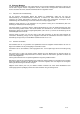
105 Diagrama de Bloques interno Filtración AC Suministrador potencia interna Panel microprocesador Unidad visor Entrada/salida remota Consumibles AC (TV, PC, refrigerador, luz, bombas, etc.) Fusible Panel de potencia Fusible Filtración DC Fuente DC (Batería, Pila de combustible, Aerodinámico, PV, suministrados de potencia, etc.) Fusible 106 Información de Seguridad 106.1 Información general Lea el manual detenidamente antes de instalar o hacer funcionar el inversor.
106.2 Funcionamiento con baterías La utilización de baterías de un modo incorrecto puede causar peligro para personas, animales o el medioambiente. Compruebe la información del fabricante de las baterías para una instalación y funcionamiento seguros. Si el ácido de la batería entra en contacto con la piel o la ropa, lávese inmediatamente con jabón y agua. Si el ácido se pone en contacto con los ojos, deje correr inmediatamente agua fría durante al menos 20 minutos y consiga asistencia médica cuanto antes.
108 Mantenimiento Sólo se requiere un poco de mantenimiento para mantener su inversor y un sistema confiable que funcione. El inversor debe ser apagado durante las actividades de reparación y/o mantenimiento. También debe ser asegurado contra un encendido inesperado e involuntario. Por lo tanto, apague la conexión entre las baterías y el inversor y esté seguro de que terceros no pueden invertir las medidas tomadas. Los pasos siguientes deben ser emprendidos al menos una vez al año.
111 Instalación SWING pro modelo 111.1 Cableado de la corriente continua La posición del interruptor en el panel delantero debe ser OFF. Un fusible de alta potencia debe ser instalado directo a la batería para proteger el cableado de la corriente continua (no para la Swing pro 200-12-230).
112 Mando a distancia del Swing pro 350 sólo El mando a distancia disponible opcional permite el control a distancia del inversor. El mando a distancia debe estar conectado al puerto remoto localizado en la parte de atrás del inversor. Usando el mando a distancia el interruptor principal del inversor debe estar en la posición "ON". Puerto remoto 113 Operación El Inversor está controlado por un interruptor ON / OFF localizado en el panel delantero del inversor.
115 Datos técnicos 200VA 350VA 73/85 V 1.
116 Instalación JAZZ pro modelo 116.1 Cableado de la corriente continua La posición del interruptor en el panel delantero debe estar en OFF. Precaución: Primero conecte los cables de la corriente continua reunidos con el inversor y en un segundo paso conéctelo con la batería. Advertencia: siempre conecte primero el cable negativo con la batería. Un fusible de alta potencia debe ser instalado directo a la batería para proteger el cableado de la corriente continua. Corriente continua según la tabla de abajo.
117 Mando a distancia El mando a distancia disponible opcional permite controlar a distancia el inversor. El mando a distancia debe estar conectado al puerto remoto (conector RS-232) localizado en la parte trasera del inversor. Antes de usar el mando a distancia el interruptor principal del inversor debe estar en la posición "ON". 118 Configuración del inversor antes de la operación 118.
119 Operación El Inversor está controlado por un interruptor ON / OFF localizado en el panel delantero del inversor. Encendido Ponga el interruptor de potencia en la posición ON; usted oirá tres bip. Después de esto, usted oirá el sonido continuo de la alarma interna. Entonces, el voltaje de la corriente alterna se muestra en el visor. El Inversor está listo para usarse. Apagado Apague en la posición "OFF". Todos los LED'S son oscuros. La salida de inversor está en OFF.
Seleccione VAC Intervalo 100120 Precisión +/- 1% AMP WATT VDC 200240 0-20 0-2KW 10-16 20-32 +/- 1% +/- 1% +/- 3% +/- 2% +/- 2% TEMP Hz 42-62 0-120°C 50 +/- 2% +/- 1% +/- 0.01 +/- 0.01 60 120.7 Indicador de protección de sobrevoltaje: (OVP) El indicador de sobrevoltaje indica que el inversor de potencia se ha apagado porque su voltaje de entrada excedió el voltaje de entrada máximo. 120.
121 Datos técnicos JAZZ pro 700 JAZZ pro 1000 78/85 V 1.
122 Instalación HIPHOP pro modelo 122.1 Cableado de la corriente continua La posición del interruptor en el panel delantero debe estar en OFF. Precaución: Primero conecte los cables de la corriente continua reunidos con el inversor y en un segundo paso conéctelo con la batería. Advertencia: siempre conecte primero el cable negativo con la batería. Un fusible de alta potencia debe ser instalado directo a la batería para proteger el cableado de la corriente continua.
122.2 Cableado de la corriente alterna HIPHOP pro 1500 & HIPHOP pro 2000 Use el conector de la corriente alterna incluido para conectar la carga de la corriente alterna a la salida del inversor. HIPHOP pro 3000 Para conectar el cable AC, abra la placa delantera (6 tornillos). Tire del cable AC a través de la rejilla del terminal de la placa delantera y conéctelo a la abrazadera de AC.
123 Mando a distancia El mando a distancia disponible opcional permite controlar a distancia el inversor. El mando a distancia debe estar conectado al puerto remoto (conector RS-232) localizado en la parte trasera del inversor. Antes de usar el mando a distancia el interruptor principal del inversor debe estar en la posición "ON". 124 Configuración del inversor antes de la operación 124.
125 Operación El Inversor está controlado por un interruptor ON / OFF localizado en el panel delantero del inversor. Encendido Ponga el interruptor de potencia en la posición ON; usted oirá tres bip. Después de esto, usted oirá el sonido continuo de la alarma interna. Entonces, el voltaje de la corriente alterna se muestra en el visor. El Inversor está listo para usarse. Apagado Apague en la posición "OFF". Todos los LED'S son oscuros. La salida de inversor está en OFF.
Seleccione VAC Intervalo 100120 Precisión +/- 1% AMP WATT VDC 200240 0-20 0-3KW 10-16 20-32 +/- 1% +/- 1% +/- 3% +/- 2% +/- 2% TEMP Hz 42-62 0-120°C 50 +/- 2% +/- 1% +/- 0.01 +/- 0.01 60 126.7 Indicador de protección de sobrevoltaje: (OVP) El indicador de sobrevoltaje indica que el inversor de potencia se ha apagado porque su voltaje de entrada excedió el voltaje de entrada máximo. 126.
127 Datos técnicos HIPHOP pro 1500 HIPHOP pro 2000 84/85 V 1.
HIPHOP pro 3000 85/85 V 1.