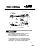
Install guide 6030 HEAT OFF COOL MENU FAN ON AUTO PROG Caution • Your thermostat is a precise instrument, handle it with care. • Turn off electricity to the appliance before installing or servicing thermostat or any part of the system. • Do not turn electricity back on until work is completed. • Do not short (jumper) across electric terminals at control on furnace or air conditioner to test the system. This will damage the thermostat and void your warranty.
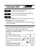
Install guide 6030 Caution Tools To avoid electrical shock and to prevent damage to the furnace, air conditioner, and thermostat, disconnect the power supply before beginning work. This can be done at the circuit breaker, or at the appliance. You will need a small Phillips screwdriver and possibly a drill with 3/16-in. (4.8mm) bit for wall mounting. Location Replacement installations - mount the new thermostat in place of the old one. New installations - follow the guidelines listed below.
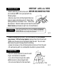
Remove old unit IMPORTANT : LABEL ALL WIRES BEFORE DISCONNECTING THEM! Caution W • Switch electricity to the furnace and air conditioner OFF; then proceed with the following steps. • Remove cover from old thermostat. Most are snap-on types and simply pull off. Some have locking screws on the side or front. These must be loosened. Note the letters printed near the terminals. Attach labels (enclosed) to each wire for identification.
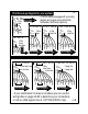
PG Before you Connect Wires 5 Please follow these guidelines for safe and secure wire connections. • Easy Terminals do not require stripping the wire. • Clip any bare wire from previous installation. • Take care not to damage the labels for each wire in handling. • Fan wires out as illustrated with 6030 below the wall opening. • Wires will dress behind the 6030 and up over the terminal area. • Use the Step-By-Step diagram as your guide. • Do not bunch wires behind 6030.
PG Find the set-up diagram for your system WIRES • Find the referenece page with your wiring diagram and jumper set-up information. Remember, the C wire is optional.
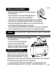
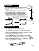
Mount the 6030 Wall • Hold the 6030 against the wall, with the wires coming over the top above terminal block. The 6030 will cover the hole 6030 in the wall. • Position 6030 for best appearance. Use the optional standoffs if more space for wires is needed behind the 6030. • Attach the base to the wall with the screws provided. • If you are mounting the base to sheet rock or if you are using the old mounting holes, use the plastic anchors provided. Drill a 3/16-in.(4.
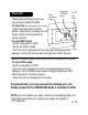
Check Unit Touch Temperature Display Temperature UP/DOWN Arrows PG Follow these procedures to verify you have correctly installed the 6030. To check Fan: (If you connected the G wire - fan relay) • Switch the FAN switch to the ON position. Verify that air is blowing from the system. Return to AUTO position for normal operation. To check HEAT mode: • Set the mode switch to HEAT. • Set the fan switch to AUTO. • Touch the room temperature and the heat target temperature will be displayed.
PG 13 Power Options BATTERIES ONLY - This thermostat can run on batteries only using 2AAA alkaline batteries. The batteries will last at least 1 year; replace the batteries once a year or when the low battery icon comes on the display. If the batteries are not replaced, the thermostat will shut off the HVAC and then stop working. 24VAC - This thermostat can run on the HVAC 24VAC (C wire) if available.
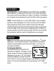
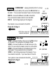
WIRES 2 WIRE HEAT Heating GAS MILLIVOLT or 24vac PG 15 STEP 1 - Connect the R (or RH) wire to the RH terminal on SET the 6030. This connects the Heater Power to the thermostat. JUMPERS STEP 2 - Connect the W wire to the W on the 6030. 12 A45 This connects the heater control line to the 6030. B STEP 3 - Set Config jumpers per this diagram. 3 GAS Milivolt Heat Your Heater is now connected to the 6030. Please Go To Page 9 C OPTIONAL POWER W R 6030 NOTE: Wires marked with dotted line are optional.
WIRES W Y RH G 4 Wire Heat/Cool PG 17 STEP 1 - Connect the W wire to the W terminal on the SET JUMPERS thermostat. This connects to the heater control line. STEP 2 - Connect the Y wire to the Y terminal on the 3 or 12 A45 6030. This connects to the Cooler compressor. STEP 3 - Connect the RH or R wire to the RH terminal on B the thermostat. This connects the Heater/Cooler Power. STEP 4 - Connect the G wire to the G terminal on the Thermostat. This connects to the Fan.
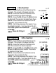
WIRES B or O Y R G 4 Wire Heat Pump w/o Aux PG 19 STEP 1 - Connect O wire to the O terminal or B wire to the B terminal on the 6030. (If you have both O and B - connect O wire to O terminal DO NOT connect B to B terminal - see pg 24 Trane for B wire terminal) This connects the change-over valve. 3 STEP 2 - Connect the Y wire to Y on the 6030. 12 A45 This connects the Compressor. SET B STEP 3 - Connect the R wire to RH on the 6030. JUMPERS This connects to the 24vac power.
WIRES W2 W Y Y2 RH G 2 Stage Heat and Cool STEP 1 - Connect the W wire to the W terminal and W2 to W2 on the 6030. This connects 2 stages of heat. STEP 2 - Connect the Y wire to the Y terminal and Y2 wire to Y2 on the 6030. This connects 2 stages of cool. STEP 3 - Connect the RH or R wire to the RH terminal on the thermostat. This connects the Heater/Cooler Power. STEP 4 - Connect the G wire to the G terminal on the Thermostat. This connects to the Fan. STEP 5 - Set Config jumpers per this diagram.
6030 Features PG 23 This thermostat can be used with all millivolt and 24VAC heating and cooling systems. It cannot be used with line voltage systems. This thermostat is digital and your desired heat or cool temperatures can be easily be set on the large touch screen with the UP/DOWN arrows. A minimum 4 minute off time protects heating and cooling systems from damage. This thermostat uses a new technique called sequential staging for more comfort with faster reaction to requested temperature changes.
Wire Reference cont Your Wires PG Zoned Systems 25 Your Wires Ritetemp Terminal 2 wire Zoned Hot Water R RH W W Ritetemp Terminal Lennox Heat Pump V or VR or R RH M or Y Y Y or W or W2 W2 F or G G R or O O X or X2 or C C 3 Wire Zoned Hot Water Motor Driven Valves R RH W W Y (the 3rd wire) A Trane Products [American Standard] B C W or W1 W2 3 Wire Zoned Hot Water Solenoid Valves R RH W A Y (the 3rd wire) W Jumper Reference 3 2 1 A 4 B Configuration jumpers allow your 6030 to be adapted to man
HEAT OFF COOL MENU FAN ON AUTO PROG Customer Support: 877-505-2353 or Visit our website www.ritetemp-thermostats.