
Quick Start Manual


STEP 1 - Connect O wire to the O terminal or B wire to the B terminal on
the 6030. (If you have both O and B - connect O wire to O terminal
DO NOT connect B to B terminal - see pg 24 Trane for B wire terminal)
This connects the change-over valve.
STEP 2 - Connect the Y wire to Y on the 6030.
This connects the Compressor.
STEP 3 - Connect the R wire to RH on the 6030.
This connects to the 24vac power.
STEP 4 - Connect the G wire to the G terminal on the
6030. This connects the Fan.
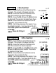
STEP 5 - Set Config jumpers per this diagram.
Your HVAC system is now connected
to the 6030.
Please Go T o Page 9
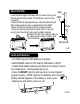
B
or
O Y R G
PG 19
PG 20
4 Wire Heat Pump w/o Aux
OPTIONAL POWER
WIRES
STEP 1 - Connect O wire to the O terminal or B wire to the B terminal on
the 6030. (If you have both O and B -connect O wire to O terminal DO NOT
connect B to B terminal - see pg 24 Trane for B wire terminal)
STEP 2 - Connect the W2 wire to W2 on the 6030.
STEP 3 - Connect the Y wire to Y on the 6030.
STEP 4 - Connect the R wire to RH on the 6030.
STEP 5 - Connect the G wire to G on the 6030.
STEP 6 - Set Config jumpers per this diagram.
Set jumper 1 if you have Gas or Oil aux heat.
Your HVAC system is now connected
to the 6030.
Please Go T o Page 9
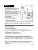
B
or
O W2 Y RH G
5 Wire Heat Pump w/ Aux Heat
WIRES
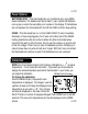
6030
Terminals
YB
R G
C
HEAT PUMP SYSTEM
O
C B O
W2
W
Y Y2 RH RC G A
C B O
W2
W
Y Y2 RH RC G A
SET
JUMPERS
or
or
SET
JUMPERS
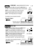
6030
Terminals
Y
W2
B
R G
C
HEAT PUMP SYSTEM
O
OPTIONAL POWER
or
or
?
1 2 4 5
3
B
A
1 2 4 5
3
B
A