CC-Link Communication Converter COM-JC [For FB100/FB400/FB900] Instruction Manual ® RKC INSTRUMENT INC.
z CC-Link is a registered trademark of Mitsubishi Electric Co. Ltd. z Modbus is a registered trademark of Schneider Electric. z The name of each programmable controller (PLC) means the products of each manufacturer. z Company names and product names used in this manual are the trademarks or registered trademarks of the respective companies. All Rights Reserved, Copyright © 2005, RKC INSTRUMENT INC.
Thank you for purchasing this RKC product. In order to achieve maximum performance and ensure proper operation of your new instrument, carefully read all the instructions in this manual. Please place the manual in a convenient location for easy reference. SYMBOLS WARNING : This mark indicates precautions that must be taken if there is danger of electric shock, fire, etc., which could result in loss of life or injury.
CAUTION z This product is intended for use with industrial machines, test and measuring equipment. (It is not designed for use with medical equipment and nuclear energy.) z This is a Class A instrument. In a domestic environment, this instrument may cause radio interference, in which case the user may be required to take additional measures. z This instrument is protected from electric shock by reinforced insulation.
CONTENTS Page 1. OUTLINE ............................................................................ 1 1.1 Product Check ................................................................................................ 2 1.2 Model Code .................................................................................................... 2 1.3 Parts Description ............................................................................................ 3 2. HANDLING PROCEDURES ...............................
Page 7. COMMUNICATION DATA LIST ....................................... 26 7.1 Remote Input/Output .................................................................................... 26 7.1.1 1 station occupied 1 time .................................................................................. 27 7.1.2 4 stations occupied 1 time ................................................................................ 29 7.1.3 4 stations occupied 2 times .......................................................
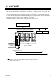
1. OUTLINE This manual describes the communication specifications, mounting, wiring, setting and data instructions for the CC-Link communication converter COM-JC. CC-Link communication converter COM-JC (hereafter called COM-JC) is communication converter to connect the RKC temperature controller (FB100/400/900) to a programmable controller (Mitsubishi Electric PLC MELSEC series: hereafter called PLC) for CC-Link. In addition, COM-JC is connected to CC-Link as the Remote device station.
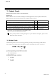
1. OUTLINE 1.1 Product Check Before using this product, check each of the following. z Model code z Check that there are no scratches or breakage in external appearance (case, front panel, terminal, etc). z Check that all of the accessories delivered are complete.
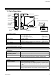
1. OUTLINE 1.3 Parts Description Terminal cover Terminal base Mainframe Indication lamps DIP switch Station number setting switch [Details of Indication lamps] RD SD RUN FAIL CC-Link connection terminals (COM.
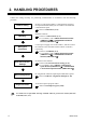
2. HANDLING PROCEDURES Conduct the setting necessary for performing communication in accordance with the following procedure. COM-JC Setting Mounting Wiring and Connection PLC and Controller Settings Device Assignment Program Creation Set the CC-Link station number, Communication speed and Occupied station/Extended cyclic of COM-JC and Controller communication speed. Refer to 5. SETTING (P. 16) Install the COM-JC. • Refer to 3. MOUNTING (P.
3. MOUNTING This chapter describes installation environment, mounting cautions, dimensions and mounting procedures. ! WARNING To prevent electric shock or instrument failure, always turn off the power before mounting or removing the instrument. 3.1 Mounting Cautions (1) This instrument is intended to be used under the following environmental conditions.
3. MOUNTING 3.2 Dimensions (Unit: mm) 9.5 30 3 5 78 125 109.5 3.3 DIN Rail Mounting Mounting procedures 1. Pull down the mounting bracket at the bottom of the instrument (A). Attach the hooks on the top of the instrument to the DIN rail and push the lower section into place on the DIN rail (B). 2. Slide the mounting bracket up to secure the instrument to the DIN rail (C).
3. MOUNTING Removal procedures 1. Turn the power OFF. 2. Remove the wiring. 3. Pull down a mounting bracket with a blade screwdriver (A). Lift the instrument from bottom, and take it off (B). (B) Lift and take off (A) Pull down 3.4 Panel Mounting Mounting procedures 1. Pull down the mounting bracket (A) until locked and that a mounting hole appears. 2.
4. WIRING This chapter describes wiring cautions, terminal configuration and connections. 4.1 Wiring Cautions ! WARNING z To prevent electric shock or instrument failure, do not turn on the power until all wiring is completed. Make sure that the wiring is correct before applying power to the instrument. z To prevent electric shock or instrument failure, turn off the power before connecting or disconnecting the instrument and peripheral equipment.
4. WIRING 4.2 Terminal Configuration The terminal layout is as follows. Controller communication Upper-side terminal RS-485 T/R(A) 1 T/R(B) 3 2 7 6 5 1 5 SG 4 4 : The part of internal wiring Power supply 11 10 14 9 13 9 8 Ground 12 8 12 + DC 24 V − Lower-side terminal FG As controller communication terminal No. 1, 4 and 5 are internally connected to terminal No. 3, 6 and 7, any terminals can be used. As ground and power supply terminal No.
4. WIRING 4.3 Connection to PLC Connection method The PLC (Master station) and COM-JC make multi-drop connection in CC-Link dedicated cable Ver. 1.10. PLC Master station COM-JC Termination resistor Termination resistor CC-Link dedicated cable Ver. 1.10 Up to 61 stations Station to station cable length: 20 cm or more Up to 64 stations: 1 station occupied 1 time z Communication speed and maximum transmitter distance (Use the CC-Link dedicated cable Ver. 1.10) Communication speed 10 Mbps 5 Mbps 2.
4. WIRING Terminal numbers and signal details CC-Link connection terminals 1: DA 2: DB 3: DG 4: SLD 5: FG Terminal screws Screws size: M3 Recommended tightening torque: 0.4 N⋅m (4 kgf⋅cm) Terminal No. 1 2 3 4 5 Signal name Data A Data B Data ground Shield Frame ground Symbol DA DB DG SLD FG Cable color Blue White Yellow Grounding wire (Shield) ⎯ The CC-Link connecting terminal cannot do on-line installation or dismount for terminal block of dismount impossibility.
4. WIRING Connection diagram Always connect a termination resistor between the DA and DB terminals of the module to be located at the far end. Termination resistor: 110 Ω ± 5 % 1/2 W Master station TR COM-JC COM-JC DA DA DA DB DB DB DG DG DG SLD SLD SLD FG CC-Link dedicated cable Ver. 1.10 FG CC-Link dedicated cable Ver. 1.10 TR FG TR: Termination resistor The CC-Link dedicated cable Ver. 1.10 is provided by the customer.
4. WIRING 4.4 Connection to Controller Conduct wiring between the COM-JC and controller (FB100/400/900) as shown in the following. When conducting wiring to the FB100/400/900, always conduct wiring to the Communication 1 terminal. Communication terminal number and signal details Terminal No.
4. WIRING 4.5 Installation of Termination Resistor If communication errors occur frequently due to the operation environment or the communication distance, connect termination resistors to the COM-JC and the controller. Procedure for setting a termination resistor to Controller communication (RS-485) and its setting position are described in the following.
4. WIRING 3. Turn on the termination resistor transfer switch in the terminal base. The COM-JC is shipped from the factory with the selector switch set to “ON: Termination resistor connected.” ON OFF Termination resistor transfer switch Termination resistor OFF Termination resistor ON (120 Ω 1/2 W) Factory set value: ON A terminal base of the state which removed module mainframe 4. Push the mainframe thus separated in the terminal base until firmly locked.
5. SETTING ! WARNING z To prevent electric shock or instrument failure, always turn off the power before setting the switch. z To prevent electric shock or instrument failure, never touch any section other than those instructed in this manual. CAUTION Do not separate the mainframe from the terminal base with the power turned on. If so, instrument failure may result. 5.1 Station Number Setting Set the station number of CC-Link. For this setting, use a small blade screwdriver.
5. SETTING 5.2 Communication Speed Setting The rotary switch at the left side of the mainframe sets the communication speed of the CC-Link. For this setting, use a small slotted screwdriver. When set to any value out of the setting range, the COM-JC becomes the FAIL state. Communication speed setting switch Left side view Setting range: 0 to 4 Factory set value: 0 (156 kbps) z Communication speed and maximum transmitter distance (Use the CC-Link dedicated cable Ver. 1.
5. SETTING 5.3 Occupied Station/Extended Cyclic and Controller Communication Speed Setting The DIP switch at the left side of the mainframe sets the occupied station/extended cyclic and controller communication speed.
5. SETTING 5.4 Controller Setting [Controller communication conditions: Use communication 1 side] • Device address: 1 to 99 (Zero is not settable) The device address numbers must be continuous starting from 1. • Communication protocol: Modbus-RTU • Communication speed: 9600 bps, 19200 bps, 38400 bps Match the communication speed of the FB series controller to that of the COM-JC. The communication speed of the COM-JC can be adjusted with a DIP switch.
6. CC-Link COMMUNICATION 6.1 Communication Between Master Station and COM-JC (Remote Device Station) The COM-JC which is a remote device station can process Remote input (RX), Remote output (RY) and Remote registers (RWw and RWr).
6. CC-Link COMMUNICATION (6) The transmission data of the CPU device set with the automatic refresh parameters is stored in the Remote register RWw buffer memory. [Writing to the Remote register RWw] (7) The data stored in the Remote register RWw buffer memory is automatically sent to the Remote register RWw of COM-JC (Remote device station). (8) The Remote register RWr data of a COM-JC (Remote device station) is automatically stored in the Remote register RWr buffer memory of the master station.
6. CC-Link COMMUNICATION 6.2 CC-Link Flag Operation Remote input/output and Remote register flag operations are as follows. [Example] When the Occupied station/Extended cyclic of COM-JC is set to 1 station occupied 1 time. Initialize request processing at power on z Initialize processing request from Remote device station (COM-JC) If the COM-JC is initialized at power on, the Initialize data processing request flag [RX(n+1)8] is turned on.
6. CC-Link COMMUNICATION Error flag/Error reset processing If the Error reset request flag [RY(n+1)A] is turned on while the Error status flag [RX(n+1)A] is turned on, the Error status flag history is cleared and the flag [RX(n+1)A] turns off. Error status flag [RX(n+1)A] ON OFF Error reset request flag [RY(n+1)A] ON OFF ON Remote ready [RX(n+1)B] OFF Extension number for display selection processing The content of the extended display remote register is selected.
6. CC-Link COMMUNICATION Extension number for setting selection processing The content of the extended setting remote register is selected and the set value is changed. After the Extension number for setting [RYn6 to RYnB] is set, turn on the Extended setting flag (Setting update flag) [RYnD]. After the content of the Remote register [RWwn to RWwn+3] is set, check that Extended setting completion [RXnD] is turned on and then turn off the Extended setting flag (Setting update flag) [RYnD].
6. CC-Link COMMUNICATION 6.3 Processing of Numeric Data Values Numeric data values used via communication with the PLC and processed by COM-JC include those with and without decimal points and also those with minus signs. z For numeric data value without decimal point If there is no decimal point, the value is processed as it is. In parameters which only have ON or OFF status, 1 = ON, 0 = OFF. [Example] A signal wire for temperature input is disconnected and the burnout state occurs.
7. COMMUNICATION DATA LIST 7.1 Remote Input/Output Remote input (RX) and Remote output (RY) is ON/OFF data. “n” in the table is the address assigned to the master station by the station number setting. It can be calculated by the following equation. However, the computing equation is when a network is configured only by using our COM-JCs and the number of all Occupied station/Extended cyclic are at the same setting.
7. COMMUNICATION DATA LIST 7.1.
7.
7. COMMUNICATION DATA LIST 7.1.
7. COMMUNICATION DATA LIST Continued from the previous page.
7. COMMUNICATION DATA LIST Continued from the previous page.
7. COMMUNICATION DATA LIST Continued from the previous page.
7.
7. COMMUNICATION DATA LIST Continued from the previous page.
7. COMMUNICATION DATA LIST 7.1.
7. COMMUNICATION DATA LIST Continued from the previous page.
7. COMMUNICATION DATA LIST Continued from the previous page.
7. COMMUNICATION DATA LIST Continued from the previous page.
7. COMMUNICATION DATA LIST Continued from the previous page.
7. COMMUNICATION DATA LIST Continued from the previous page.
7. COMMUNICATION DATA LIST Continued from the previous page.
7. COMMUNICATION DATA LIST Continued from the previous page.
7.
7. COMMUNICATION DATA LIST Continued from the previous page.
7. COMMUNICATION DATA LIST 7.2 Remote Register Remote registers (RWr, RWw) are numeric data. “n” in the table is the address assigned to the master station by the station number setting. It can be calculated by the following equation. However, the computing equation is when a network is configured only by using our COM-JCs and the number of all Occupied station/Extended cyclic are at the same setting.
7. COMMUNICATION DATA LIST 7.2.1 1 station occupied 1 time (1 controller assignment) Remote register (RWr) Data direction: COM-JC (Remote device station) → Master station (PLC) Data capacity: 4-word Address RWrn Communication item Device address 1 RWrn+1 Measured value (PV) Manipulated output value (MV1) Unused For extended area display RWrn+2 RWrn+3 Data range Input scale low to Input scale high −5.0 to +105.
7. COMMUNICATION DATA LIST 7.2.
7. COMMUNICATION DATA LIST 7.2.
7. COMMUNICATION DATA LIST 7.2.
7. COMMUNICATION DATA LIST 7.2.
7.
7. COMMUNICATION DATA LIST 7.2.
7.
7. COMMUNICATION DATA LIST 7.3 Extension Number Communication items which are handled in the extension areas of the Remote registers (RWr and RWw) are specified by the extension number, If the necessary data is selected from a list of extension numbers and that extension number is set by remote output, the data can be handled in the Remote registers (RWr and RWw).
7. COMMUNICATION DATA LIST When write data z Setting of extension number for setting Extension number for setting sets it with Remote output RYn6 to RynB and RY(n+1)8 to RY(n+1)A. Bit image RY(n+1)A RY(n+1)9 RY(n+1)8 RYnB RYnA RYn9 RYn8 RYn7 RYn6 Bit 8 Bit 7 Bit 6 Bit 5 Bit 4 Bit 3 Bit 2 Bit 1 Bit 0 Bit data: 0: OFF 1: ON [Decimal number: 0 to 511] For the 1 station occupied 1 time setting, setting range of extension number becomes RYn6 to RYnB [Decimal number: 0 to 63].
7. COMMUNICATION DATA LIST Extension number list Attribute: RO: Read only data [Remote device station (COM-JC) → Master station (PLC)] R/W: Read and Write data [Remote device station (COM-JC) ↔ Master station (PLC)] Data related multi-memory area function Reading data of unused setting items are factory set values. Unused setting items may not be written. To do so will not cause an error however and data will be rejected.
7. COMMUNICATION DATA LIST Continued from the previous page. Extension Communication item number 9 Event 1 set value 10 Event 2 set value 11 Reserved AttriData range bute R/W Deviation: −Input span to +Input span Varies with the setting of the Decimal point position selection. Process and set value: Input scale low to Input scale high Varies with the setting of the Decimal R/W point position selection. Manipulated output value (MV1 or MV2): −5.0 to +105.
7. COMMUNICATION DATA LIST Continued from the previous page. Extension Communication item number 24 Heater break alarm 1 (HBA1) set value 25 26 27 Decimal point position Manipulated output value (MV2) monitor [cool-side] Proportional band [cool-side] AttriData range bute R/W 0.0 to 30.0 A (CTL-6-P-N) 0.0 to 100.0 A (CTL-12-S56-10L-N) (0.0: Unused) If there is no Current transformer 1 (CT1) or CT1 is assigned to “0: None,” set to RO (Read only data).
7. COMMUNICATION DATA LIST Continued from the previous page. Extension Communication item number 31 Set value (SV) monitor 32 Error code 33 34 Memory area transfer Control response parameter 35 36 Unused Input type AttriData range bute RO Setting limiter low to Setting limiter high Varies with the setting of the Decimal point position selection.
7. COMMUNICATION DATA LIST Continued from the previous page. Extension Communication item number 37 Setting change rate limiter (up) 41 Event 1 differential gap 42 Event 2 differential gap AttriData range bute R/W 0 to Input span/unit time * (0: Unused) Varies with the setting of the Decimal point position selection.
7. COMMUNICATION DATA LIST Continued from the previous page. Extension Communication item number 47 Output limiter low [MV1] 48 49 50 Unused Unused Control loop break alarm (LBA) time 51 LBA deadband 52 53 54 Unused Unused Event 3 set value (EV3) 55 Event 4 set value (EV4) 56 Event 3 type 57 Event 4 type AttriData range bute R/W −5.0 % to Output limiter high [MV1] Position proportioning PID control: Becomes valid only when there is Feedback resistance (FBR) input and it does not break.
7. COMMUNICATION DATA LIST Continued from the previous page. Extension Communication item number 58 Event 3 differential gap 59 Event 4 differential gap AttriData range bute R/W c Deviation, process or set value: 0 (0.0, 0.00) to Input span (Unit: °C [°F]) Varies with the setting of the Decimal point position selection. d MV: 0.0 to 110.
7. COMMUNICATION DATA LIST Continued from the previous page.
7. COMMUNICATION DATA LIST Continued from the previous page. Extension Communication item number 111 Area soak time 112 Integral time [cool-side] 113 Derivative time [cool-side] 114 Unused AttriData range bute R/W 0 to 11999 seconds or 0 to 5999 minutes Data range of Area soak time can be selected on the Soak time unit. [FB100] When the Digital input (DI) assignment (Extension No. 170) value is 6 to 12, this data becomes RO (Read only data). R/W 0 to 3600 seconds or 0.0 to 1999.
7. COMMUNICATION DATA LIST Continued from the previous page.
7. COMMUNICATION DATA LIST Continued from the previous page. Extension Communication item number 152 Heater break determination point 2 153 Heater melting determination point 2 154 Unused AttriData range bute R/W 0.0 to 100.0 % of HBA2 set value (0.0: Heater break determination is invalid) If there is no Current transformer 2 (CT2) or CT2 is assigned to “0: None,” set to RO (Read only data). If Heater break alarm 2 (HBA2) corresponds to “0: Type A,” set to RO (Read only data). R/W 0.0 to 100.
7. COMMUNICATION DATA LIST Continued from the previous page. Extension Communication item number 165 Burnout direction 171 Unused AttriData range bute R/W 0: Upscale 1: Downscale Valid only when the TC input and Voltage (low) input are selected. R/W 0: Unused 1: Used R/W 0: 50 Hz 1: 60 Hz If power frequency measurement was made possible with CT input and/or Power feed forward (PFF) input applied, set to RO (Read only data).
7. COMMUNICATION DATA LIST Continued from the previous page. Extension Communication item number 181 Timer 1 a 182 Timer 2 183 Timer 3 AttriData range bute R/W 0.0 to 600.0 seconds R/W Customization tool is necessary when the timer function is availed. R/W 184 Timer 4 R/W 185 186 Unused Energized/De-energized ⎯ R/W 187 Alarm (ALM) lamp lighting condition 1 a R/W 188 Alarm (ALM) lamp lighting condition 2 a R/W 189 Output status at STOP mode R/W Factory set value 0.0 0.0 0.0 0.
7. COMMUNICATION DATA LIST Continued from the previous page.
7. COMMUNICATION DATA LIST Continued from the previous page. Extension Communication item number 205 Unused 206 Event 2 interlock 216 Event 4 delay timer Unused AttriFactory Data range bute set value ⎯ ⎯ ⎯ R/W 0: Unused 0 1: Used R/W 0.0 to 600.0 seconds 0.
7. COMMUNICATION DATA LIST Continued from the previous page.
7. COMMUNICATION DATA LIST Continued from the previous page. Extension Communication item number 232 Unused 233 Unused 234 SV tracking 235 236 237 238 239 240 241 242 243 244 245 246 247 248 AttriFactory Data range bute set value ⎯ ⎯ ⎯ ⎯ ⎯ ⎯ R/W 0: Unused 1 1: Used R/W 0: MV1 or MV2 in Auto mode is used. 0 MV transfer function 1: When selected by Digital input (DI): [Action taken when changed to Manual mode from Auto MV1 or MV2 in previous Manual mode mode] is used.
7. COMMUNICATION DATA LIST Continued from the previous page. Extension Communication item number 249 Power feed forward selection [Unused on the FB100] 250 Power feed forward gain [Unused on the FB100] 251 Derivative action 252 Attribute R/W 0: Unused 1: Used R/W 0.01 to 5.00 R/W 0: Measured value derivative 1: Deviation derivative In Position proportioning PID control, action becomes Measured value derivative regardless of the setting. 0.000 to 1.
7. COMMUNICATION DATA LIST Continued from the previous page. Extension Communication item number 265 Integrated output limiter 266 267 268 269 270 271 272 273 274 275 276 277 278 AttriFactory Data range bute set value R/W 0.0 to 200.0 % of control motor time 150.0 (0.0: OFF) Becomes invalid when there is Feedback resistance (FBR) input.
7. COMMUNICATION DATA LIST Continued from the previous page. Extension Communication item number 279 Integral time adjusting factor [cool-side] 280 Derivative time adjusting factor [cool-side] 281 Proportional band limiter high [heat-side] AttriData range bute R/W 0.01 to 10.00 times R/W R/W Factory set value 1.00 1.00 TC/RTD inputs: 0 to Input span, 0.0 to Input span or 0.00 to Input span (Unit: °C [°F]) Varies with the setting of the Decimal point position selection. Voltage (V)/Current (I) inputs: 0.
7. COMMUNICATION DATA LIST Continued from the previous page. Extension Communication item number 321 Bar graph display 324 Direct key 2 [Unused on the FB100] 325 Direct key 3 [Unused on the FB100] 326 Unused AttriData range bute R/W 0: No display 1: MV1 or MV2 2: PV 3: SV monitor 4: Deviation value 5: CT1 input value 6: CT2 input value R/W 1 to 100 digit/dot Becomes valid when the Bar graph display is “4: Deviation value,” “5: CT1 input value” or “6: CT2 input value.
7. COMMUNICATION DATA LIST Continued from the previous page. Extension Communication item number 343 Power feed forward input value monitor [Unused on the FB100] 344 Unused y y y 349 350 AttriData range bute RO 0.0 to 160.0 % Display in the percentage of the load voltage (Rated value).
7. COMMUNICATION DATA LIST Continued from the previous page.
7.
7.
8. USAGE EXAMPLE This chapter describes a usage example of CC-Link communication. 8.1 Handling Procedures Preparations of Configuration Instrument Mounting and Wiring Refer to 8.2 System Configuration (P. 82) • For mounting and wiring of the COM-JC, refer to 3. MOUNTING (P. 5) and 4. WIRING (P. 8). • For mounting and wiring of the controller (FB400), refer to FB400/FB900 Installation Manual (IMR01W01-E). • For mounting and wiring of PLC, refer to PLC Instruction Manual.
8. USAGE EXAMPLE 8.2 System Configuration In this usage example, described the following system configuration. Mitsubishi PLC MELSEC Q series CC-Link system Master local unit QJ 61BT11N (Master station) Station number: 0 Communication speed: 156 kbps CPU unit Q02HCPU CC Link Ver. 1.
8. USAGE EXAMPLE 8.3 Use Instruments Setting Set the PLC, COM-JC and controller as the following. PLC setting For operating of CC-Link system master local unit QJ61BT11N and MELSEC sequencer programming software GX Developer, refer to PLC Instruction Manual.
8.
8. USAGE EXAMPLE 8.4 Device Assignments Example According to the contents set by 8.3 Use Instruments Setting (P. 83), each device is assigned.
8. USAGE EXAMPLE Continued from the previous page.
8.
8. USAGE EXAMPLE 8.5 Sample Program Program conditions Station number of COM-JC: 1 Number of Occupied station/Extended cyclic: 1 station occupied 1 time (2 controllers assignment) Automatic refresh device assignment: Refer to 8.4 Device Assignments Example (P. 84).
8. USAGE EXAMPLE Sample program When the PLC initial processing (PLC STOP → RUN). BKRST RST Y100F Control STOP of controller. Turn off the control RUN/STOP transfer (Y100F: RY0F). SET Y1019 Turn on the Initialize data setting request flag (Y1019: RY19). K3 Turn off the Extension number setting flag for display (M0). M0 When no initial data processing is finished with the initial data processing requested.
8. USAGE EXAMPLE Continued from the previous page. When the COM-JC is in the remote ready state and no display extension number setting is processed yet. Remote ready (X101B: RX1B) ON Extension number setting flag for display (M0) OFF X101B M0 When Measured value (PV)/Manipulated output M1 value (M1) is transferred to Measured value (PV). RST Y1000 When Measured value (PV)/Manipulated output value (M1) is transferred to Manipulated output M1 value (M1). SET Y1000 Set the extension number for display.
8. USAGE EXAMPLE Continued from the previous page. When Measured value (PV)/Manipulated output value (M1) is transferred to M1 Manipulated output value (M1). MOV W2 D2 MOV W3 D3 Store the Manipulated output value (MV1) of controller 1 into the data register D2. Store the Extension area for display (W002: RWr2) of controller 1 into the data register D2. Store the Manipulated output value (MV1) of controller 2 into the data register D3.
8. USAGE EXAMPLE Continued from the previous page. RST Y100D The Extension setting completion flag (X100D: RX0D) is turned OFF. X100D SET Y100D SET M2 When the extension setting is finished and the setting extension number has been set. Extended setting completion flag (X100D: RX0D) ON Extension number setting flag for setting (M2) ON X100D M2 Y100F Turn off the Extended setting flag (Y100D: RY0D) Turn on the Extended setting flag (Y100D: RY0D). Extension number setting end for setting.
9. TROUBLESHOOTING This section explains possible causes and solutions if any abnormality occurs in the instrument. For any inquiries or to confirm the specifications of the product, please contact RKC sales office or the agent. If it is necessary to replace a device, always strictly observe the warnings below. ! WARNING z To prevent electric shock or instrument failure, always turn off the system power before replacing the instrument.
9. TROUBLESHOOTING COM-JC Problem FAIL lamp flashes RUN lamp OFF SD/RD lamp OFF Possible cause Solution No connection, disconnection, breakage or wrong wiring of CC-Link cable Confirm the connection method or condition and connect correctly A termination resistor of CC-Link is not connected Confirm the termination resistor, and connected correctly The number of Occupied station/ Extended cyclic setting of the COM-JC differs from that of the master instrument (PLC).
10. SPECIFICATIONS CC-Link communication Protocol: CC-Link Ver. 2.00/Ver. 1.10 Communication speed: 156 kbps, 625 kbps, 2.5 Mbps, 5 Mbps, 10 Mbps Communication distance: Refer to table shown below Communication speed 10 Mbps 5 Mbps 2.5 Mbps 625 kbps 156 kbps Maximum network length 100 m 200 m 400 m 900 m 1200 m Station number: 1 to 61 (4 stations occupied 1 time, 4 stations occupied 2 times) 1 to 64 (1 station occupied 1 time) Connection cable: CC-Link dedicated cable Ver. 1.
10.
10. SPECIFICATIONS Operating environment: Avoid the following conditions when selecting the mounting location. • Rapid changes in ambient temperature which may cause condensation. • Corrosive or inflammable gases. • Direct vibration or shock to the mainframe. • Water, oil, chemicals, vapor or steam splashes. • Direct air flow from an air conditioner. • Exposure to direct sunlight. • Excessive heat accumulation. Weight: Approx. 220 g Dimensions: 30 × 125 × 109.
MEMO 98 IMR01Y06-E6
The first edition: APR. 2005 [IMQ00] The sixth edition: SEP.
R RKC INSTRUMENT INC. HEADQUARTERS: 16-6, KUGAHARA 5-CHOME, OHTA-KU TOKYO 146-8515 JAPAN PHONE: 03-3751-9799 (+81 3 3751 9799) FAX: 03-3751-8585 (+81 3 3751 8585) E-mail: info@rkcinst.co.jp Website: http://www.rkcinst.com/ IMR01Y06-E6 SEP.