
Instruction manual

7. COMMUNICATION DATA LIST
IMR01Y06-E6
65
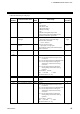
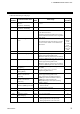
Continued from the previous page.
Extension
number
Communication item
Attri-
bute
Data range
Factory
set value
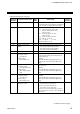
143
PV low input cut-off
R/W
0.00 to 25.00 % of input span
If the Input square root extraction corresponds
to “0: Unused,” set to RO (Read only data).
0.00
144
Set lock level
R/W
Bit data
Bit 0: Lock only setting items other
than SV and Event set value
(EV1 to EV4).
Bit 1: Lock only Event set value
(EV1 to EV4)
Bit 2: Lock only Set value (SV)
Bit 3 to Bit 15: Unused
Data 0: Unlock 1: Lock
[Decimal number: 0 to 7]
0
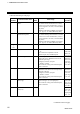
145 Unused
⎯ ⎯ ⎯
146
Backup memory state
monitor
RO
0: The content of the backup memory does
not coincide with that of the RAM.
1: The content of the backup memory
coincides with that of the RAM.
⎯
147 Unused
⎯
⎯
⎯
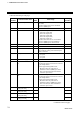
148
RS bias
Cascade control:
Cascade bias
Ratio setting:
Ratio setting bias
R/W
−
Input span to +Input span
Varies with the setting of the Decimal point
position selection.
[FB100]
When the Remote setting (RS) input is not
provided, this data becomes RO (Read only
data).
0, 0.0, 0.00
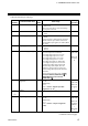
149
RS digital filter
Cascade control:
Cascade digital filter
Ratio setting:
Ratio setting digital
filter
R/W
0.0 to 100.0 seconds
(0.0: Unused)
[FB100]
When the Remote setting (RS) input is not
provided, this data becomes RO (Read only
data).
0.0
150
RS ratio
Cascade control:
Cascade ratio
Ratio setting:
Ratio setting ratio
R/W
0.001 to 9.999
[FB100]
When the Remote setting (RS) input is not
provided, this data becomes RO (Read only
data).
1.000
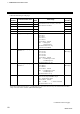
151
Heater break alarm 2
(HBA2) set value
R/W
When CT is CTL-6-P-N:
0.0 to 30.0 A (0.0: Not used)
When CT is CTL-12-S56-10L-N:
0.0 to 100.0 A (0.0: Not used)
If there is no Current transformer 2 (CT2) or
CT2 is assigned to “0: None,” set to RO (Read
only data).
0.0
Continued on the next page.