
Instruction manual

7. COMMUNICATION DATA LIST
IMR01Y06-E6
67
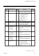
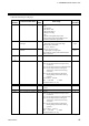
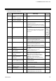
Continued from the previous page.
Extension
number
Communication item
Attri-
bute
Data range
Factory
set value
165
Burnout direction
R/W
0: Upscale
1: Downscale
Valid only when the TC input and Voltage
(low) input are selected.
0
166
Square root extraction
R/W
0: Unused
1: Used
0
167
Power supply frequency
R/W
0: 50 Hz
1: 60 Hz
If power frequency measurement was made
possible with CT input and/or Power feed
forward (PFF) input applied, set to RO (Read
only data).
0
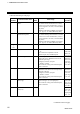
168
Sampling cycle
R/W
0: 50 ms
1: 100 ms
2: 250 ms
1
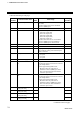
169
Remote setting input type
R/W
14: Current input 0 to 20 mA DC
15: Current input 4 to 20 mA DC
16: Voltage (high) input 0 to 10 V DC
17: Voltage (high) input 0 to 5 V DC
18: Voltage (high) input 1 to 5 V DC
19: Voltage (low) input 0 to 1 V DC
20: Voltage (low) input 0 to 100 mV DC
21: Voltage (low) input 0 to 10 mV DC
If changed to Voltage (high) inputs from
Current/Voltage (low) inputs, select the
hardware by the input selector switch [for
Remote setting (SR) input] at the side of the
instrument.
For the selecting procedure, refer to FB100
Instruction Manual (IMR01W16-E) or
FB400/FB900 Instruction Manual
(IMR01W03-E).
Based on
model code.
When not
specifying:
15
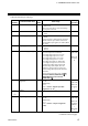
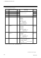
170
Digital input (DI)
assignment
R/W
[FB100]
1 to 26
[FB400/900]
1 to 8
Refer to Table 1 “Digital input (DI)
assignment” (P. 79).
Based on
model code.
When not
specifying:
1
171 Unused
⎯
⎯
⎯
y
y
y
179
180
Output assignment
R/W
[FB100]
1 to 15
[FB400/900]
1 to 7
Refer to Table 2 “Output assignment”
(P. 80).
Based on
model code.
When not
specifying:
FB100:
1
FB400/900:
2
Continued on the next page.