
Instruction manual

7. COMMUNICATION DATA LIST
IMR01Y06-E6
69
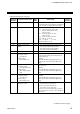
Continued from the previous page.
Extension
number
Communication item
Attri-
bute
Data range
Factory
set value
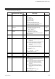
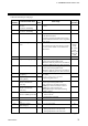
190
Transmission output type
R/W
0: None
1: PV
2: SV monitor
3: Deviation value
4: MV1 [heat-side] *
5: MV2 [cool-side]
6: SV
7: Remote setting (RS) input value
* For Position proportioning PID control:
Feedback resistance input value
1
191
Transmission output
scale high
R/W
When the PV, SV, SV monitor and RS:
Input scale low to Input scale high
When the MV1 and MV2:
−5.0 to +105.0 %
When the deviation value:
−Input span to +Input span
Varies with the setting of the Decimal point
position selection.
Input scale
high
192
Transmission output
scale low
R/W
Input scale
low
193 Unused
⎯
⎯
⎯
y
y
y
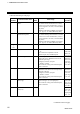
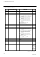
199
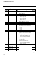
200
Force ON of Event 1 action
R/W
Bit data
Bit 0: Event output turned on at input error
occurrence
Bit 1: Event output turned on in Manual mode
Bit 2: Event output turned on during the
Autotuning (AT) function is being
executed
Bit 3: Event output turned on during the
Setting change rate limiter is being
operated
Bit 4 to Bit 15: Unused
Data 0: Invalid 1: Valid
[Decimal number: 0 to 15]
0
201 Unused
⎯ ⎯ ⎯
202
Event 1 interlock
R/W
0: Unused
1: Used
0
203
Event 1 delay timer
R/W
0.0 to 600.0 seconds
0.0
204
Force ON of Event 2 action
R/W
Bit data
Bit 0: Event output turned on at input error
occurrence
Bit 1: Event output turned on in Manual mode
Bit 2: Event output turned on during the
Autotuning (AT) function is being
executed
Bit 3: Event output turned on during the
Setting change rate limiter is being
operated
Bit 4 to Bit 15: Unused
Data 0: Invalid 1: Valid
[Decimal number: 0 to 15]
0
Continued on the next page.