
Instruction manual

7. COMMUNICATION DATA LIST
IMR01Y06-E6
74
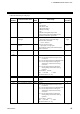
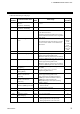
Continued from the previous page.
Extension
number
Communication item
Attri-
bute
Data range
Factory
set value
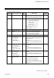
265
Integrated output limiter
R/W
0.0 to 200.0 % of control motor time
(0.0: OFF)
Becomes invalid when there is Feedback
resistance (FBR) input.
150.0
266
Control motor time
R/W
5 to 1000 seconds
10
267
Valve action at STOP
R/W
0: Close-side output OFF,
Open-side output OFF
1: Close-side output ON,
Open-side output OFF
2: Close-side output OFF,
Open-side output ON
Becomes valid when there is no Feedback
resistance (FBR) input or the Feedback
resistance (FBR) input is disconnected.
0
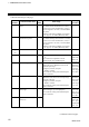
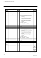
268 Unused
⎯ ⎯ ⎯
269 Unused
⎯ ⎯ ⎯
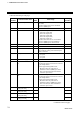
270
AT bias
R/W
−
Input span to +Input span
Varies with the setting of the Decimal point
position selection.
0, 0.0 or 0.00
271
AT cycles
R/W
0: 1.5 cycles
1: 2.0 cycles
2: 2.5 cycles
3: 3.0 cycles
1
272
AT differential gap time
R/W
0.0 to 50.0 seconds
10.0
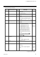
273
Output value with AT turned
on
R/W
Output value with AT turned off to +105.0 %
Actual output values become those restricted
by the Output limiter.
Position proportioning PID control:
Becomes valid only when there is
Feedback resistance (FBR) input and it
does not break (high limit of Feedback
resistance input at AT).
105.0
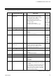
274
Output value with AT turned
off
R/W
−
105.0 % to Output value with AT turned on
Actual output values become those restricted
by the Output limiter.
Position proportioning PID control:
Becomes valid only when there is
Feedback resistance (FBR) input and it
does not break (low limit of Feedback
resistance input at AT).
−105.0
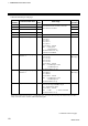
275
Proportional band adjusting
factor [heat-side]
R/W
0.01 to 10.00 times
1.00
276
Integral time adjusting
factor [heat-side]
R/W 1.00
277
Derivative time adjusting
factor [heat-side]
R/W 1.00
278
Proportional band adjusting
factor [cool-side]
R/W 1.00
Continued on the next page.