
Instruction manual

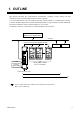

1. OUTLINE
IMR01Y06-E6
3
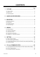
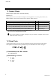
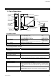
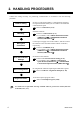
1.3 Parts Description
Station number
setting switch
Indication
lamps
Terminal cove
r
Front view
Left side view
Terminal base
Mainframe
CC-Link communication
speed setting switch
Terminal cove
r
Mounting
bracket
CC-Link
connection
terminals
(COM.PORT)
FAIL
RUN
SD
RD
[Details of Indication lamps
]
DIP switch
z Indication lamps
FAIL [Red]
• When instrument abnormally: ON
• CC-Link setting error: ON
• CC-Link operation error: Flashes slowly
• CC-Link setting is changed: Flashes rapidly
RUN [Green]
• When normally: ON
• Operation error: Flashes slowly
• During controller communication initialization: Flashes rapidly
SD [Green]
During CC-Link data send: ON
RD [Green]
During CC-Link data receive: ON
z CC-Link connection terminals
COM. PORT
Terminals for PLC (Master) connection
z Switches
Station number setting switch
Set the station number for CC-Link
CC-Link communication
peed setting switch
Set the communication speed for CC-Link
DIP switch
• Set the number of Occupied station/Extension cyclic for CC-Link
• Set the communication speed for controller communication
z Other
Terminal cover
Terminal cover above and below the COM-JC
Mounting bracket
• Used for the DIN rail mounting
• When panel mounted, two mounting brackets are required for the
upper and lower sides (one required for the upper side: separately
sold).
Terminal base
Part of the terminal and base of COM-JC
(There is the termination resistor transfer switch in the inside of
terminal base)
Mainframe
Part of the mainframe of COM-JC