RKC INSTRUMENT INC. Temperature Controller Driver 1 System Configuration....................................................................................................... 3 2 Selection of External Device .......................................................................................... 11 3 Example of Communication Setting ............................................................................... 12 4 Setup Items ....................................................................
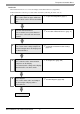
Temperature Controller Driver Introduction This manual describes how to connect the Display and the External Device (target PLC). In this manual, the connection procedure will be described by following the below sections: 1 System Configuration This section shows the types of External Devices which can be connected and SIO type. )"1 System Configuration" (page 3) 2 Selection of External Device Select a model (series) of the External Device to be connected and connection method.
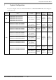
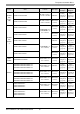
Temperature Controller Driver 1 System Configuration The system configuration in the case when the External Device of RKC INSTRUMENT INC. and the Display are connected is shown. CB FB*2 SIO Type Setting Example Cable Diagram Terminal Block on RS422/485 the controller.
Temperature Controller Driver HA*3 Link I/F SIO Type Setting Example Cable Diagram Terminal Block on the controller.
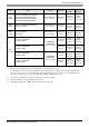
Temperature Controller Driver Link I/F SIO Type Setting Example Cable Diagram Modular connector 1 on the controller. RS232C Setting Example 38 (page 86) Cable Diagram 11 (page 152) Setting Modular connector RS422/485 Example 39 on the controller.
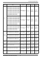
Temperature Controller Driver CPU*1 Series Link I/F SIO Type Setting Example Cable Diagram RS232C G9 - * - -1/A Terminal Block on the controller. Setting Example 26 (page 62) Cable Diagram 2 (page 114) REX-G9 G9 - * - -4/A Setting Terminal Block on RS422/485 Example 27 the controller. (4 wire) (page 64) Cable Diagram 10 (page 148) G9 - * - -2/A Setting Terminal Block on RS422/485 Example 28 the controller.
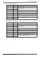
Temperature Controller Driver CPU*1 Series SRZ (Z-TIO) Z-TIO-A Z-TIO-B Z-TIO-C Z-TIO-D - SRZ (Z-DIO) Z-DIO-A Z-DIO-A - SRZ (Z-CT) Z-CT-A / Z-CT-A /N Link I/F SIO Type Setting Example Cable Diagram / / N / / N - Setting Terminal Block on RS422/485 Example 40 the controller. (2 wire) (page 90) Cable Diagram 13 (page 154) / /N Setting Terminal Block on RS422/485 Example 41 the controller.
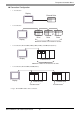
Temperature Controller Driver Connection Configuration • 1:1 Connection Display External Drive • 1:n Connection External Drive External Drive External Drive Display Maximum number of connections: 16 units • 1:n Connection (For the SRZ (Z-TIO), SRZ (Z-DIO), and SRZ (Z-CT) Series) Display External Drive Maximum number of connections: 16 units • 1:n Connection (For the SRZ (Z-COM) Series) Display External Drive Z-COM module *1 *1 Up to 16 Z-COM modules can be connected.
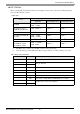
Temperature Controller Driver IPC COM Port When connecting IPC with an External Device, the COM port used depends on the series and SIO type. Please refer to the IPC manual for details.
Temperature Controller Driver DIP switch setting: RS-422/485 (4 wire) DIP switch Setting Description 1 OFF 2 ON 3 ON 4 OFF Output mode of SD (TXD) data: Always output 5 OFF Terminal resistance (220Ω) insertion to SD (TXD): None 6 OFF Terminal resistance (220Ω) insertion to RD (RXD): None 7 OFF Short-circuit of SDA (TXA) and RDA (RXA): Not available 8 OFF Short-circuit of SDB (TXB) and RDB (RXB): Not available 9 OFF 10 OFF Reserved (always OFF) SIO type: RS-422/485 RS (RTS) Auto
Temperature Controller Driver 2 Selection of External Device Select the External Device to be connected to the Display. Setup Items Setup Description Maker Select the maker of the External Device to be connected. Select "RKC INSTRUMENT INC.". Driver Select a model (series) of the External Device to be connected and connection method. Select "Temperature Controller". Check the External Device which can be connected in "Temperature Controller" in system configuration.
Temperature Controller Driver 3 Example of Communication Setting Examples of communication settings of the Display and the External Device, recommended by Pro-face, are shown. 3.1 Setting Example 1 Settings of GP-Pro EX Communication Settings To display the setting screen, select [Device/PLC Settings] from [System setting window] in workspace.
Temperature Controller Driver Settings of External Device Communication setting of the external device is set with the SET, Shift, UP and Down keys located on the front face of the temperature controller. Please refer to the temperature controller manual for details. Procedure 1. While depressing the SET key, press the Shift key to change from PV/SV display mode to communication setting mode. 2. Press the SET key and select parameters. 3. Press UP/Down keys to change the setting. 4.
Temperature Controller Driver 3.2 Setting Example 2 Settings of GP-Pro EX Communication Settings To display the setting screen, select [Device/PLC Settings] from [System setting window] in workspace. Device Setting To display the setting screen, click ([Setting]) of External Device you want to set from [Device-Specific Settings] of [Device/PLC Settings].
Temperature Controller Driver Settings of External Device Communication setting of the external device is set with the SET, Shift, UP and Down keys located on the front face of the temperature controller. Please refer to the temperature controller manual for details. Procedure 1. While depressing the SET key, press the Shift key and hold until display mode changes from PV/SV display mode to engineering mode. 2. Press the Up key several times to set the F60, and press the SET key. 3.
Temperature Controller Driver 3.3 Setting Example 3 Settings of GP-Pro EX Communication Settings To display the setting screen, select [Device/PLC Settings] from [System setting window] in workspace. Device Setting To display the setting screen, click ([Setting]) of External Device you want to set from [Device-Specific Settings] of [Device/PLC Settings].
Temperature Controller Driver Settings of External Device Communication setting of the external device is set with the SET, Shift, UP and Down keys located on the front face of the temperature controller. Please refer to the temperature controller manual for details. Procedure 1. While depressing the SET key, press the Shift key and hold until display mode changes from PV/SV display mode to engineering mode. 2. Press the Up key several times to set the F60, and press the SET key. 3.
Temperature Controller Driver 3.4 Setting Example 4 Settings of GP-Pro EX Communication Settings To display the setting screen, select [Device/PLC Settings] from [System setting window] in workspace. Device Setting To display the setting screen, click ([Setting]) of External Device you want to set from [Device-Specific Settings] of [Device/PLC Settings].
Temperature Controller Driver Settings of External Device Communication setting of the external device is set with the SET, Shift, UP and Down keys located on the front face of the temperature controller. Please refer to the temperature controller manual for details. Procedure 1. While depressing the SET key, press the Shift key and hold until display mode changes from PV/SV display mode to engineering mode. 2. Press the Up key several times to set the F60, and press the SET key. 3.
Temperature Controller Driver 3.5 Setting Example 5 Settings of GP-Pro EX Communication Settings To display the setting screen, select [Device/PLC Settings] from [System setting window] in workspace. Device Setting To display the setting screen, click ([Setting]) of External Device you want to set from [Device-Specific Settings] of [Device/PLC Settings].
Temperature Controller Driver Settings of External Device Communication setting of the external device is set with the SET, Shift, UP and Down keys located on the front face of the temperature controller. Please refer to the temperature controller manual for details. Procedure 1. While depressing the SET key, press the Shift key to change from SV setting & monitor mode to setup setting mode. 2. Press the SET key and select parameters. 3. Press UP/Down keys to change the setting. 4.
Temperature Controller Driver 3.6 Setting Example 6 Settings of GP-Pro EX Communication Settings To display the setting screen, select [Device/PLC Settings] from [System setting window] in workspace. Device Setting To display the setting screen, click ([Setting]) of External Device you want to set from [Device-Specific Settings] of [Device/PLC Settings].
Temperature Controller Driver Settings of External Device Communication setting of the external device is set with the SET, Shift, UP and Down keys located on the front face of the temperature controller. Please refer to the temperature controller manual for details. Procedure 1. While depressing the SET key, press the Shift key to change from SV setting & monitor mode to setup setting mode. 2. Press the SET key and select parameters. 3. Press UP/Down keys to change the setting. 4.
Temperature Controller Driver 3.7 Setting Example 7 Settings of GP-Pro EX Communication Settings To display the setting screen, select [Device/PLC Settings] from [System setting window] in workspace. Device Setting To display the setting screen, click ([Setting]) of External Device you want to set from [Device-Specific Settings] of [Device/PLC Settings].
Temperature Controller Driver Settings of External Device Communication setting of the external device is set with the SET, Shift, UP and Down keys located on the front face of the temperature controller. Please refer to the temperature controller manual for details. Procedure 1. While depressing the SET key, press the Shift key to change from SV setting & monitor mode to setup setting mode. 2. Press the SET key and select parameters. 3. Press UP/Down keys to change the setting. 4.
Temperature Controller Driver 3.8 Setting Example 8 Settings of GP-Pro EX Communication Settings To display the setting screen, select [Device/PLC Settings] from [System setting window] in workspace. Device Setting To display the setting screen, click ([Setting]) of External Device you want to set from [Device-Specific Settings] of [Device/PLC Settings].
Temperature Controller Driver Settings of External Device Communication setting of the external device is set with the SET, Shift, UP and Down keys located on the front face of the temperature controller. Please refer to the temperature controller manual for details. Procedure 1. While depressing the SET key, press the
Temperature Controller Driver 3.9 Setting Example 9 Settings of GP-Pro EX Communication Settings To display the setting screen, select [Device/PLC Settings] from [System setting window] in workspace. Device Setting To display the setting screen, click ([Setting]) of External Device you want to set from [Device-Specific Settings] of [Device/PLC Settings].
Temperature Controller Driver Settings of External Device Communication setting of the external device is set with the SET, Shift, UP and Down keys located on the front face of the temperature controller. Please refer to the temperature controller manual for details. Procedure 1. While depressing the SET key, press the
Temperature Controller Driver 3.10 Setting Example 10 Settings of GP-Pro EX Communication Settings To display the setting screen, select [Device/PLC Settings] from [System setting window] in workspace. Device Setting To display the setting screen, click ([Setting]) of External Device you want to set from [Device-Specific Settings] of [Device/PLC Settings].
Temperature Controller Driver Settings of External Device Communication setting of the external device is set with the SET, Shift, UP and Down keys located on the front face of the temperature controller. Please refer to the temperature controller manual for details. Procedure 1. While depressing the SET key, press the
Temperature Controller Driver 3.11 Setting Example 11 Settings of GP-Pro EX Communication Settings To display the setting screen, select [Device/PLC Settings] from [System setting window] in workspace. Device Setting To display the setting screen, click ([Setting]) of External Device you want to set from [Device-Specific Settings] of [Device/PLC Settings].
Temperature Controller Driver Settings of External Device Communication setting of the external device is set with the SET, Shift, UP and Down keys located on the front face of the temperature controller. Please refer to the temperature controller manual for details. Procedure 1. While depressing the Shift key, press the SET key to change from PV display mode to communication setting mode. Device address of setting item is displayed. 2. Press the SET key to display the communication item to be set.
Temperature Controller Driver 3.12 Setting Example 12 Settings of GP-Pro EX Communication Settings To display the setting screen, select [Device/PLC Settings] from [System setting window] in workspace. Device Setting To display the setting screen, click ([Setting]) of External Device you want to set from [Device-Specific Settings] of [Device/PLC Settings].
Temperature Controller Driver Settings of External Device Communication setting of the external device is set with the SET, Shift, UP and Down keys located on the front face of the temperature controller. Please refer to the temperature controller manual for details. Procedure 1. While depressing the Down key, press the SET key to change from PV display mode to device configuration setting mode. Communication parameter group is displayed. 2.
Temperature Controller Driver 3.13 Setting Example 13 Settings of GP-Pro EX Communication Settings To display the setting screen, select [Device/PLC Settings] from [System setting window] in workspace. Device Setting To display the setting screen, click ([Setting]) of External Device you want to set from [Device-Specific Settings] of [Device/PLC Settings].
Temperature Controller Driver Settings of External Device Communication setting of the external device is set with the SEL, MODE, UP and Down keys located on the front face of the temperature controller. Please refer to the temperature controller manual for details. Procedure 1. Set the external device to operation STOP status. Press the MODE key to display "Operation execution (RUN) /STOP transfer," and press the Down key to set the mode to STOP. 2.
Temperature Controller Driver 3.14 Setting Example 14 Settings of GP-Pro EX Communication Settings To display the setting screen, select [Device/PLC Settings] from [System setting window] in workspace. Device Setting To display the setting screen, click ([Setting]) of External Device you want to set from [Device-Specific Settings] of [Device/PLC Settings].
Temperature Controller Driver Settings of External Device Communication setting of the external device is set with the rotary switch on the front face of the temperature controller and the dip switch in the temperature controller. Please refer to the temperature controller manual for details. Procedure 1. Set module address with the rotary switch on the front face of the temperature controller. 2.
Temperature Controller Driver 3.15 Setting Example 15 Settings of GP-Pro EX Communication Settings To display the setting screen, select [Device/PLC Settings] from [System setting window] in workspace. Device Setting To display the setting screen, click ([Setting]) of External Device you want to set from [Device-Specific Settings] of [Device/PLC Settings].
Temperature Controller Driver Settings of External Device Communication setting of the external device is set with the rotary switch on the front face of the temperature controller and the dip switch in the temperature controller. Please refer to the temperature controller manual for details. Procedure 1. Set module address with the rotary switch on the front face of the temperature controller. 2.
Temperature Controller Driver 3.16 Setting Example 16 Settings of GP-Pro EX Communication Settings To display the setting screen, select [Device/PLC Settings] from [System setting window] in workspace. Device Setting To display the setting screen, click ([Setting]) of External Device you want to set from [Device-Specific Settings] of [Device/PLC Settings].
Temperature Controller Driver Settings of External Device Communication setting of the external device is set with the SET, Shift, UP and Down keys located on the front face of the temperature controller. Please refer to the temperature controller manual for details. Procedure 1. While depressing the SET key, press the Shift key to change from PV/SV display mode to communication setting mode. 2. Press the SET key and select parameters. 3. Press UP/Down keys to change the setting. 4.
Temperature Controller Driver 3.17 Setting Example 17 Settings of GP-Pro EX Communication Settings To display the setting screen, select [Device/PLC Settings] from [System setting window] in workspace. Device Setting To display the setting screen, click ([Setting]) of External Device you want to set from [Device-Specific Settings] of [Device/PLC Settings].
Temperature Controller Driver Settings of External Device Communication setting of the external device is set with the SET, Shift, UP and Down keys located on the front face of the temperature controller. Please refer to the temperature controller manual for details. Procedure 1. While depressing the SET key, press the Shift key to change from PV/SV display mode to communication setting mode. 2. Press the SET key and select parameters. 3. Press UP/Down keys to change the setting. 4.
Temperature Controller Driver 3.18 Setting Example 18 Settings of GP-Pro EX Communication Settings To display the setting screen, select [Device/PLC Settings] from [System setting window] in workspace. Device Setting To display the setting screen, click ([Setting]) of External Device you want to set from [Device-Specific Settings] of [Device/PLC Settings].
Temperature Controller Driver Settings of External Device Communication setting of the external device is set with the SEL, MONI/MODE, UP and Down keys located on the front face of the temperature controller. Please refer to the temperature controller manual for details. Procedure 1. Depress the SEL key for 2 seconds to change from PV display mode to engineer setting mode. Parameter group is displayed. 2. Press the Up/Down keys to display the parameter group, "PG8." 3.
Temperature Controller Driver 3.19 Setting Example 19 Settings of GP-Pro EX Communication Settings To display the setting screen, select [Device/PLC Settings] from [System setting window] in workspace. Device Setting To display the setting screen, click ([Setting]) of External Device you want to set from [Device-Specific Settings] of [Device/PLC Settings].
Temperature Controller Driver Settings of External Device Communication setting of the external device is set with the SEL, MONI/MODE, UP and Down keys located on the front face of the temperature controller. Please refer to the temperature controller manual for details. Procedure 1. Depress the SEL key for 2 seconds to change from PV display mode to engineer setting mode. Parameter group is displayed. 2. Press the Up/Down keys to display the parameter group, "PG8." 3.
Temperature Controller Driver 3.20 Setting Example 20 Settings of GP-Pro EX Communication Settings To display the setting screen, select [Device/PLC Settings] from [System setting window] in workspace. Device Setting To display the setting screen, click ([Setting]) of External Device you want to set from [Device-Specific Settings] of [Device/PLC Settings].
Temperature Controller Driver Settings of External Device Communication setting of the external device is set with the rotary switch on the front face of the temperature controller and the dip switch in the temperature controller. Please refer to the temperature controller manual for details. Procedure 1. Unit address is set with the rotary switch on the front face of the temperature controller. 2.
Temperature Controller Driver 3.21 Setting Example 21 Settings of GP-Pro EX Communication Settings To display the setting screen, select [Device/PLC Settings] from [System setting window] in workspace. Device Setting To display the setting screen, click ([Setting]) of External Device you want to set from [Device-Specific Settings] of [Device/PLC Settings].
Temperature Controller Driver Settings of External Device Communication setting of the external device is set with the rotary switch on the front face of the temperature controller and the dip switch in the temperature controller. Please refer to the temperature controller manual for details. Procedure 1. Unit address is set with the rotary switch on the front face of the temperature controller. 2.
Temperature Controller Driver 3.22 Setting Example 22 Settings of GP-Pro EX Communication Settings To display the setting screen, select [Device/PLC Settings] from [System setting window] in workspace. Device Setting To display the setting screen, click ([Setting]) of External Device you want to set from [Device-Specific Settings] of [Device/PLC Settings].
Temperature Controller Driver Settings of External Device Communication setting of the external device is set with the rotary switch on the front face of the temperature controller and the dip switch in the temperature controller. Please refer to the temperature controller manual for details. Procedure 1. Unit address is set with the rotary switch on the front face of the temperature controller. 2.
Temperature Controller Driver 3.23 Setting Example 23 Settings of GP-Pro EX Communication Settings To display the setting screen, select [Device/PLC Settings] from [System setting window] in workspace. Device Setting To display the setting screen, click ([Setting]) of External Device you want to set from [Device-Specific Settings] of [Device/PLC Settings].
Temperature Controller Driver Settings of External Device Communication setting of the external device is set with the SEL, MODE, UP and Down keys located on the front face of the temperature controller. Please refer to the temperature controller manual for details. Procedure 1. Set the external device to the operation STOP status. Press the MODE key several times to display "Operation execution (RUN) /STOP transfer," and press the Down key to set the mode to STOP. 2.
Temperature Controller Driver 3.24 Setting Example 24 Settings of GP-Pro EX Communication Settings To display the setting screen, select [Device/PLC Settings] from [System setting window] in workspace. Device Setting To display the setting screen, click ([Setting]) of External Device you want to set from [Device-Specific Settings] of [Device/PLC Settings].
Temperature Controller Driver Settings of External Device Communication setting of the external device is set with the SEL, MODE, UP and Down keys located on the front face of the temperature controller. Please refer to the temperature controller manual for details. Procedure 1. Set the external device to the operation STOP status. Press the MODE key several times to display "Operation execution (RUN) /STOP transfer," and press the Down key to set the mode to STOP. 2.
Temperature Controller Driver 3.25 Setting Example 25 Settings of GP-Pro EX Communication Settings To display the setting screen, select [Device/PLC Settings] from [System setting window] in workspace. Device Setting To display the setting screen, click ([Setting]) of External Device you want to set from [Device-Specific Settings] of [Device/PLC Settings].
Temperature Controller Driver Settings of External Device Communication setting of the external device is set with the SEL, MODE, UP and Down keys located on the front face of the temperature controller. Please refer to the temperature controller manual for details. Procedure 1. Set the external device to the operation STOP status. Press the MODE key several times to display "Operation execution (RUN) /STOP transfer," and press the Down key to set the mode to STOP. 2.
Temperature Controller Driver 3.26 Setting Example 26 Settings of GP-Pro EX Communication Settings To display the setting screen, select [Device/PLC Settings] from [System setting window] in workspace. Device Setting To display the setting screen, click ([Setting]) of External Device you want to set from [Device-Specific Settings] of [Device/PLC Settings].
Temperature Controller Driver Settings of External Device Communication setting of the external device is set with the MODE, PARA, >>>, UP and Down keys located on the front face of the temperature controller. Please refer to the temperature controller manual for details. Procedure 1. Press the MODE key to display "Operation execution (RUN)/STOP transfer." Press the >>> key to stop operation. 2. Press PARA key to display "Setting (PARA) screen.
Temperature Controller Driver 3.27 Setting Example 27 Settings of GP-Pro EX Communication Settings To display the setting screen, select [Device/PLC Settings] from [System setting window] in workspace. Device Setting To display the setting screen, click ([Setting]) of External Device you want to set from [Device-Specific Settings] of [Device/PLC Settings].
Temperature Controller Driver Settings of External Device Communication setting of the external device is set with the MODE, PARA, >>>, UP and Down keys located on the front face of the temperature controller. Please refer to the temperature controller manual for details. Procedure 1. Press the MODE key to display "Operation execution (RUN)/STOP transfer." Press the >>> key to stop operation. 2. Press PARA key to display "Setting (PARA) screen.
Temperature Controller Driver 3.28 Setting Example 28 Settings of GP-Pro EX Communication Settings To display the setting screen, select [Device/PLC Settings] from [System setting window] in workspace. Device Setting To display the setting screen, click ([Setting]) of External Device you want to set from [Device-Specific Settings] of [Device/PLC Settings].
Temperature Controller Driver Settings of External Device Communication setting of the external device is set with the MODE, PARA, >>>, UP and Down keys located on the front face of the temperature controller. Please refer to the temperature controller manual for details. Procedure 1. Press the MODE key to display "Operation execution (RUN)/STOP transfer." Press the >>> key to stop operation. 2. Press PARA key to display "Setting (PARA) screen.
Temperature Controller Driver 3.29 Setting Example 29 Settings of GP-Pro EX Communication Settings To display the setting screen, select [Device/PLC Settings] from [System setting window] in workspace. Device Setting To display the setting screen, click ([Setting]) of External Device you want to set from [Device-Specific Settings] of [Device/PLC Settings].
Temperature Controller Driver Settings of External Device Communication setting of the external device is set with the SET, MODE, UP and Down keys located on the front face of the temperature controller. Please refer to the temperature controller manual for details. Procedure 1. Press the SET key for 2 seconds to change from PV display mode to engineer setting mode. Parameter group is displayed. 2. Press the Up/Down keys to display the parameter group, "PG60." 3.
Temperature Controller Driver 3.30 Setting Example 30 Settings of GP-Pro EX Communication Settings To display the setting screen, select [Device/PLC Settings] from [System setting window] in workspace. Device Setting To display the setting screen, click ([Setting]) of External Device you want to set from [Device-Specific Settings] of [Device/PLC Settings].
Temperature Controller Driver Settings of External Device Communication setting of the external device is set with the SET, MODE, UP and Down keys located on the front face of the temperature controller. Please refer to the temperature controller manual for details. Procedure 1. Press the SET key for 2 seconds to change from PV display mode to engineer setting mode. Parameter group is displayed. 2. Press the Up/Down keys to display the parameter group, "PG60." 3.
Temperature Controller Driver 3.31 Setting Example 31 Settings of GP-Pro EX Communication Settings To display the setting screen, select [Device/PLC Settings] from [System setting window] in workspace. Device Setting To display the setting screen, click ([Setting]) of External Device you want to set from [Device-Specific Settings] of [Device/PLC Settings].
Temperature Controller Driver Settings of External Device Communication setting of the external device is set with the SET, MODE, UP and Down keys located on the front face of the temperature controller. Please refer to the temperature controller manual for details. Procedure 1. Press the SET key for 2 seconds to change from PV display mode to engineer setting mode. Parameter group is displayed. 2. Press the Up/Down keys to display the parameter group, "PG60." 3.
Temperature Controller Driver 3.32 Setting Example 32 Settings of GP-Pro EX Communication Settings To display the setting screen, select [Device/PLC Settings] from [System setting window] in workspace. Device Setting To display the setting screen, click ([Setting]) of External Device you want to set from [Device-Specific Settings] of [Device/PLC Settings].
Temperature Controller Driver Settings of External Device Communication setting of the external device is set with the SET, UP and Down keys located on the front face of the temperature controller. Please refer to the temperature controller manual for details. Procedure 1. While lifting up the stopper located at the lower section of the external device with a finger, pull and remove it from the case. 2. Turn on the internal switch A at upper external device and put it back in the case. 3.
Temperature Controller Driver 3.33 Setting Example 33 Settings of GP-Pro EX Communication Settings To display the setting screen, select [Device/PLC Settings] from [System setting window] in workspace. Device Setting To display the setting screen, click ([Setting]) of External Device you want to set from [Device-Specific Settings] of [Device/PLC Settings].
Temperature Controller Driver Settings of External Device Communication setting of the external device is set with the SET, UP and Down keys located on the front face of the temperature controller. Please refer to the temperature controller manual for details. Procedure 1. While lifting up the stopper located at the lower section of the external device with a finger, pull and remove it from the case. 2. Turn on the internal switch A at upper external device and put it back in the case. 3.
Temperature Controller Driver 3.34 Setting Example 34 Settings of GP-Pro EX Communication Settings To display the setting screen, select [Device/PLC Settings] from [System setting window] in workspace. Device Setting To display the setting screen, click ([Setting]) of External Device you want to set from [Device-Specific Settings] of [Device/PLC Settings].
Temperature Controller Driver Settings of External Device Communication setting of the external device is set with the SEL, MODE, UP and Down keys located on the front face of the temperature controller. Please refer to the temperature controller manual for details. Procedure 1. Depress the SEL key for 2 seconds to change from PV display mode to engineer setting mode. Parameter group is displayed. 2. Press the Up/Down keys to display the parameter group, "PG9." 3.
Temperature Controller Driver 3.35 Setting Example 35 Settings of GP-Pro EX Communication Settings To display the setting screen, select [Device/PLC Settings] from [System setting window] in workspace. Device Setting To display the setting screen, click ([Setting]) of External Device you want to set from [Device-Specific Settings] of [Device/PLC Settings].
Temperature Controller Driver Settings of External Device Communication setting of the external device is set with the SEL, MODE, UP and Down keys located on the front face of the temperature controller. Please refer to the temperature controller manual for details. Procedure 1. Depress the SEL key for 2 seconds to change from PV display mode to engineer setting mode. Parameter group is displayed. 2. Press the Up/Down keys to display the parameter group, "PG9." 3.
Temperature Controller Driver 3.36 Setting Example 36 Settings of GP-Pro EX Communication Settings To display the setting screen, select [Device/PLC Settings] from [System setting window] in workspace. Device Setting To display the setting screen, click ([Setting]) of External Device you want to set from [Device-Specific Settings] of [Device/PLC Settings].
Temperature Controller Driver Settings of External Device Communication setting of the external device is set with the SEL, MODE, UP and Down keys located on the front face of the temperature controller. Please refer to the temperature controller manual for details. Procedure 1. Depress the SEL key for 2 seconds to change from PV display mode to engineer setting mode. Parameter group is displayed. 2. Press the Up/Down keys to display the parameter group, "PG6." 3.
Temperature Controller Driver 3.37 Setting Example 37 Settings of GP-Pro EX Communication Settings To display the setting screen, select [Device/PLC Settings] from [System setting window] in workspace. Device Setting To display the setting screen, click ([Setting]) of External Device you want to set from [Device-Specific Settings] of [Device/PLC Settings].
Temperature Controller Driver Settings of External Device Communication setting of the external device is set with the SEL, MODE, UP and Down keys located on the front face of the temperature controller. Please refer to the temperature controller manual for details. Procedure 1. Depress the SEL key for 2 seconds to change from PV display mode to engineer setting mode. Parameter group is displayed. 2. Press the Up/Down keys to display the parameter group, "PG9." 3.
Temperature Controller Driver 3.38 Setting Example 38 Settings of GP-Pro EX Communication Settings To display the setting screen, select [Device/PLC Settings] from [System setting window] in workspace. Device Setting To display the setting screen, click ([Setting]) of External Device you want to set from [Device-Specific Settings] of [Device/PLC Settings].
Temperature Controller Driver Settings of External Device Communication setting of the external device is set with the slave address setting switch on the front face of the temperature controller and the dip switch in the temperature controller. Please refer to the temperature controller manual for details. Procedure 1. Set slave address for the host link with the slave address setting switch on the front face of the temperature controller. 2.
Temperature Controller Driver 3.39 Setting Example 39 Settings of GP-Pro EX Communication Settings To display the setting screen, select [Device/PLC Settings] from [System setting window] in workspace. Device Setting To display the setting screen, click ([Setting]) of External Device you want to set from [Device-Specific Settings] of [Device/PLC Settings].
Temperature Controller Driver Settings of External Device Communication setting of the external device is set with the slave address setting switch on the front face of the temperature controller and the dip switch in the temperature controller. Please refer to the temperature controller manual for details. Procedure 1. Set slave address for the host link with the slave address setting switch on the front face of the temperature controller. 2.
Temperature Controller Driver 3.40 Setting Example 40 Settings of GP-Pro EX Communication Settings To display the setting screen, select [Device/PLC Settings] from [System setting window] in workspace.
Temperature Controller Driver Device Setting To display the setting screen, click ([Setting]) of the External Device you want to set from [Device-Specific Settings ] of [Device/PLC Settings ]. Settings of External Device Use the unit address setting switch on the front of the Temperature Controller and the DIP switch on the side of the Temperature Controller for communication settings of the External Device. Please refer to the manual of the Temperature Controller for more details. Procedure 1.
Temperature Controller Driver 3.41 Setting Example 41 Settings of GP-Pro EX Communication Settings To display the setting screen, select [Device/PLC Settings] from [System setting window] in workspace.
Temperature Controller Driver Device Setting To display the setting screen, click ([Setting]) of the External Device you want to set from [Device-Specific Settings ] of [Device/PLC Settings ]. Settings of External Device Use the unit address setting switch on the front of the Temperature Controller and the DIP switch on the side of the Temperature Controller for communication settings of the External Device. Please refer to the manual of the Temperature Controller for more details. Procedure 1.
Temperature Controller Driver 3.42 Setting Example 42 Settings of GP-Pro EX Communication Settings To display the setting screen, select [Device/PLC Settings] from [System setting window] in workspace.
Temperature Controller Driver Device Setting To display the setting screen, click ([Setting]) of the External Device you want to set from [Device-Specific Settings ] of [Device/PLC Settings ]. Settings of External Device Use the unit address setting switch on the front of the Temperature Controller and the DIP switch on the side of the Temperature Controller for communication settings of the External Device. Please refer to the manual of the Temperature Controller for more details. Procedure 1.
Temperature Controller Driver 3.43 Setting Example 43 Settings of GP-Pro EX Communication Settings To display the setting screen, select [Device/PLC Settings] from [System setting window] in workspace.
Temperature Controller Driver Device Setting To display the setting screen, click ([Setting]) of the External Device you want to set from [Device-Specific Settings ] of [Device/PLC Settings ]. Settings of External Device Use the unit address setting switch on the front of the Temperature Controller and the DIP switch on the side of the Temperature Controller for communication settings of the External Device. Please refer to the manual of the Temperature Controller for more details. Procedure 1.
Temperature Controller Driver 3.44 Setting Example 44 Settings of GP-Pro EX Communication Settings To display the setting screen, select [Device/PLC Settings] from [System setting window] in workspace.
Temperature Controller Driver Device Setting To display the setting screen, click ([Setting]) of the External Device you want to set from [Device-Specific Settings ] of [Device/PLC Settings ]. Settings of External Device Use the unit address setting switch on the front of the Temperature Controller and the DIP switch on the side of the Temperature Controller for communication settings of the External Device. Please refer to the manual of the Temperature Controller for more details. Procedure 1.
Temperature Controller Driver 3.45 Setting Example 45 Settings of GP-Pro EX Communication Settings To display the setting screen, select [Device/PLC Settings] from [System setting window] in workspace.
Temperature Controller Driver Device Setting To display the setting screen, click ([Setting]) of the External Device you want to set from [Device-Specific Settings ] of [Device/PLC Settings ]. Settings of External Device Use the unit address setting switch on the front of the Temperature Controller and the DIP switch on the side of the Temperature Controller for communication settings of the External Device. Please refer to the manual of the Temperature Controller for more details. Procedure 1.
Temperature Controller Driver 3.46 Setting Example 46 Settings of GP-Pro EX Communication Settings To display the setting screen, select [Device/PLC Settings] from [System setting window] in workspace.
Temperature Controller Driver Device Setting To display the setting screen, click ([Setting]) of the External Device you want to set from [Device-Specific Settings ] of [Device/PLC Settings ]. Settings of External Device Use the unit address setting switch on the front of the Temperature Controller and the DIP switch on the side of the Temperature Controller for communication settings of the External Device. Please refer to the manual of the Temperature Controller for more details. Procedure 1.
Temperature Controller Driver 4 Setup Items Set communication settings of the Display with GP-Pro EX or in off-line mode of the Display. The setting of each parameter must be identical to that of External Device. )"3 Example of Communication Setting" (page 12) 4.1 Setup Items in GP-Pro EX Communication Settings To display the setting screen, select [Device/PLC Settings] from [System setting window] in workspace.
Temperature Controller Driver Device Setting o display the setting screen, click ([Setting]) of External Device you want to set from [Device-Specific Settings] of [Device/PLC Settings]. When you connect multiple External Device, click from [Device-Specific Settings] of [Device/PLC Settings] to add another External Device. Setup Items Setup Description Series Select the External Device series. Device Address Enter the address of the External Device, using 0 to 99.
Temperature Controller Driver 4.2 Setup Items in Off-Line Mode • Refer to the Maintenance/Troubleshooting manual for information on how to enter off-line mode or about the operation. Cf. Maintenance/Troubleshooting Manual "2.2 Off-line Mode" Communication Settings To display the setting screen, touch [Device/PLC Settings] from [Peripheral Settings] in off-line mode. Touch the External Device you want to set from the displayed list.
Temperature Controller Driver Setup Items Wait To Send Setup Description Use an integer from 0 to 255 to enter standby time (ms) for the Display from receiving packets to transmitting next commands. Device Setting To display the setting screen, touch [Device/PLC Settings] from [Peripheral Settings]. Touch the External Device you want to set from the displayed list, and touch [Device]. Setup Items Setup Description Device/PLC Name Select the External Device for device setting.
Temperature Controller Driver Option To display the setting screen, touch [Device/PLC Settings] from [Peripheral Settings]. Touch the External Device you want to set from the displayed list, and touch [Option]. Setup Items RI/VCC Setup Description You can switch RI/VCC of the 9th pin when you select RS232C for SIO type. It is necessary to change RI/5V by changeover switch of IPC when connect with IPC. Please refer to the manual of the IPC for more detail.
Temperature Controller Driver 5 Cable Diagram The cable diagram shown below may be different from the cable diagram recommended by RKC INSTRUMENT INC. Please be assured there is no operational problem in applying the cable diagram shown in this manual. • The FG pin of the External Device body must be D-class grounded. Please refer to the manual of the External • SG and FG are connected inside the Display. When connecting SG to the External Device, design the system Device for more details.
Temperature Controller Driver *3 All GP models except GP-3200 series and AGP-3302B *4 Only the COM port which can communicate by RS-422/485 (2 wire) can be used.
Temperature Controller Driver • 1:n Connection Display D-Sub 9 pin (Socket) Termination resistance 120Ω (1/2W) Display Pin Signal name 1 RDA External Device Terminal block 2 RDB Signal name 3 SDA T/R(B) T/R(B) 7 SDB T/R(A) T/R(A) 5 SG SG SG 4 ERA 8 CSA 9 ERB 6 CSB Shield External Device Terminal block Signal name Shield Termination resistance 120Ω (1/2W) FG Shell C) When using the online adapter (CA4-ADPONL-01), the terminal block conversion adapter (CA3-ADPTRM01) by Pr
Temperature Controller Driver • 1:n Connection Display D-Sub 9 pin (Plug) Termination resistance 120Ω (1/2W) Pin Signal name 1 TERMRX 2 RDA External Device Terminal block 7 RDB Signal name 3 SDA T/R(B) T/R(B) 8 SDB T/R(A) T/R(A) 5 SG SG SG 9 TERMTX Shell FG Display CA4-ADPONL-01 Shield External Device Terminal block Signal name Shield Termination resistance 120Ω (1/2W) Your own cable E) When using the COM port conversion adapter (CA3-ADPCOM-01), the terminal block conversi
Temperature Controller Driver • 1:n Connection Termination resistance 120Ω (1/2W) Display External Device Terminal block Display D-Sub 9 pin (Socket) Pin Signal name Shield Signal name Shield External Device Terminal block Signal name 1 DATA+ T/R(B) T/R(B) 2 DATA- T/R(A) T/R(A) 3 NC SG SG 7 NC 5 GND(SG) 4 ERA 8 CSA 9 ERB 6 CSB Shell FG GP-Pro EX Device/PLC Connection Manual 113 Termination resistance 120Ω (1/2W)
Temperature Controller Driver Cable Diagram 2 Display (Connection Port) GP (COM1) ST (COM1) LT (COM1) IPC*1 PC/AT *1 Cable Notes Your own cable The cable length must be 15m or less. Only the COM port which can communicate by RS-232C can be used.
Temperature Controller Driver Cable Diagram 3 Display (Connection Port) GP*1 (COM1) AGP-3302B (COM2) ST*2 (COM2) LT (COM1) IPC*3 Cable Notes A COM port conversion adapter by Pro-face CA3-ADPCOM-01 + Terminal block conversion adapter by Pro-face CA3-ADPTRM-01 + Your own cable B Your own cable C Online adapter by Pro-face CA4-ADPONL-01 + Terminal block conversion adapter by Pro-face CA3-ADPTRM-01 + Your own cable D Online adapter by Pro-face CA4-ADPONL-01 + Your own cable GP*4 (COM2) The cable l
Temperature Controller Driver • 1:n Connection Display Shield Display Termination resistance 120Ω (1/2W) External Device Terminal block External Device Terminal block Shield Signal name Signal name Signal name RDA T(B) T(B) RDB T(A) T(A) SDA R(B) R(B) SDB R(A) R(A) SG SG SG CA3-ADPCOM-01 CA3-ADPTRM-01 Termination resistance 120Ω (1/2W) Termination resistance 120Ω (1/2W) Termination resistance 120Ω (1/2W) FG Your own cable B) When using your own cable • 1:1 Connection Display
Temperature Controller Driver • 1:n Connection Display Signal name External Device Terminal block Signal name RDA T(B) T(B) RDB T(A) T(A) SDA R(B) R(B) SDB R(A) R(A) SG SG SG Shield Display Termination resistance 120Ω (1/2W) CA4-ADPONL-01 CA3-ADPTRM-01 Termination resistance 120Ω (1/2W) External Device Terminal block Signal name Shield Termination resistance 120Ω (1/2W) Termination resistance 120Ω (1/2W) FG Your own cable D) When using the online adapter (CA4-ADPONL-01) by Pro-f
Temperature Controller Driver Cable Diagram 4 Display (Connection Port) GP*1 (COM1) AGP-3302B (COM2) ST*2 (COM2) LT (COM1) IPC*3 Cable Notes A COM port conversion adapter by Pro-face CA3-ADPCOM-01 + Terminal block conversion adapter by Pro-face CA3-ADPTRM-01 + Your own cable B Your own cable C Online adapter by Pro-face CA4-ADPONL-01 + Terminal block conversion adapter by Pro-face CA3-ADPTRM-01 + Your own cable D Online adapter by Pro-face CA4-ADPONL-01 + Your own cable GP*4 (COM2) The cable l
Temperature Controller Driver • 1:n Connection Display External Device COM.PORT 1 Modular 6 pin Shield CA3-ADPCOM-01 CA3-ADPTRM-01 External Device COM.PORT 1 Modular 6 pin Shield External Device COM.
Temperature Controller Driver C) When using the online adapter (CA4-ADPONL-01), the terminal block conversion adapter (CA3-ADPTRM01) by Pro-face and your own cable • 1:1 Connection Display Display External Device COM.PORT 1 Modular 6 pin Shield Signal name Pin Signal name RDA 4 T(B) RDB 5 T(A) SDA 2 R(B) SDB 1 R(A) SG 3 SG FG 6 Shield CA4-ADPONL-01 CA3-ADPTRM-01 Your own cable • 1:n Connection Display Display CA4-ADPONL-01 CA3-ADPTRM-01 Shield External Device COM.
Temperature Controller Driver D) When using the online adapter (CA4-ADPONL-01) by Pro-face and your own cable • 1:1 Connection Display D-Sub 9 pin (Plug) CA4-ADPONL-01 Display External Device COM.PORT 1 Modular 6 pin Pin Signal name 1 TERMRX Pin Signal name 2 RDA 4 T(B) 7 RDB 5 T(A) 3 SDA 2 R(B) R(A) Shield 8 SDB 1 5 SG 3 SG 9 TERMTX 6 Shield Shell FG Your own cable • 1:n Connection Display D-Sub 9 pin (Plug) CA4-ADPONL-01 Display External Device COM.
Temperature Controller Driver Cable Diagram 5 Display (Connection Port) GP*1 (COM1) AGP-3302B (COM2) ST*2 (COM2) LT (COM1) Cable A COM port conversion adapter by Pro-face CA3-ADPCOM-01 + Terminal block conversion adapter by Pro-face CA3-ADPTRM-01 + Your own cable B Your own cable C Online adapter by Pro-face CA4-ADPONL-01 + Terminal block conversion adapter by Pro-face CA3-ADPTRM-01 + Your own cable GP*3 (COM2) IPC*4 D Online adapter by Pro-face CA4-ADPONL-01 + Your own cable E COM port conve
Temperature Controller Driver A) When using the COM port conversion adapter (CA3-ADPCOM-01), the terminal block conversion adapter (CA3-ADPTRM-01) by Pro-face and your own cable • 1:1 Connection Display RDA External Device COM.
Temperature Controller Driver B) When using your own cable • 1:1 Connection Display D-Sub 9 pin (Socket) Pin Display Signal name External Device COM.PORT 1 Modular 6 pin RDA 2 RDB Pin Signal name 3 SDA 2 T/R(B) 7 SDB 1 T/R(A) 5 SG 3 SG 4 ERA 6 Shield 8 CSA 9 ERB 6 CSB FG Shell • Shield 1 1:n Connection Display D-Sub 9 pin (Socket) Display External Device COM.PORT 1 Modular 6 pin External Device COM.PORT 2 Modular 6 pin External Device COM.
Temperature Controller Driver C) When using the online adapter (CA4-ADPONL-01), the terminal block conversion adapter (CA3-ADPTRM01) by Pro-face and your own cable • 1:1 Connection Display RDA External Device COM.PORT 1 Modular 6 pin Signal name Display CA4-ADPONL-01 CA3-ADPTRM-01 Shield RDB Pin Signal name SDA 2 T/R(B) SDB 1 T/R(A) SG 3 SG FG 6 Shield Your own cable • 1:n Connection Display Signal name Shield RDA Display CA4-ADPONL-01 CA3-ADPTRM-01 External Device COM.
Temperature Controller Driver D) When using the online adapter (CA4-ADPONL-01) by Pro-face and your own cable • 1:1 Connection Display D-Sub 9 pin (Plug) CA4-ADPONL-01 Display Pin Signal name 1 TERMRX 2 RDA 7 RDB Pin Signal name 3 SDA 2 T/R(B) 8 SDB 1 T/R(A) 5 SG 3 SG 9 TERMTX 6 Shield Shell FG External Device COM.
Temperature Controller Driver E) When using the COM port conversion adapter (CA3-ADPCOM-01), the terminal block conversion adapter (CA3-ADPTRM-01) by Pro-face and your own cable • 1:1 Connection External Device COM.PORT 1 Modular 6 pin Display Signal name Display CA3-ADPCOM-01 CA3-ADPTRM-01 Pin Signal name RDA 2 T/R(B) RDB 1 T/R(A) SDA 3 SG SDB 6 Shield Shield SG FG Your own cable • 1:n Connection External Device COM.
Temperature Controller Driver F) When using your own cable • 1:1 Connection External Device COM.PORT 1 Modular 6 pin Display D-Sub 9 pin (Socket) Display Pin Signal name Pin Signal name 1 DATA+ 2 T/R(B) 2 DATA- 1 T/R(A) 3 NC 3 SG 7 NC 6 Shield 5 GND(SG) 4 ERA 8 CSA 9 ERB 6 CSB FG Shell • Shield 1:n Connection External Device COM.PORT 1 Modular 6 pin Display D-Sub 9 pin (Socket) Display External Device COM.PORT 2 Modular 6 pin Shield External Device COM.
Temperature Controller Driver Cable Diagram 6 Display (Connection Port) GP*1 (COM1) AGP-3302B (COM2) ST*2 (COM2) LT (COM1) IPC*3 Cable Notes A COM port conversion adapter by Pro-face CA3-ADPCOM-01 + Terminal block conversion adapter by Pro-face CA3-ADPTRM-01 + Your own cable B Your own cable C Online adapter by Pro-face CA4-ADPONL-01 + Terminal block conversion adapter by Pro-face CA3-ADPTRM-01 + Your own cable D Online adapter by Pro-face CA4-ADPONL-01 + Your own cable GP*4 (COM2) The cable l
Temperature Controller Driver • 1:n Connection Display External Device COM.PORT 3 Modular 6 pin Shield External Device COM.PORT 3 Modular 6 pin Shield Signal name Pin Signal name Pin Signal name RDA 4 T(B) 4 T(B) RDB 5 T(A) 5 T(A) SDA 2 R(B) 2 R(B) SDB 1 R(A) 1 R(A) SG 3 SG 3 SG FG 6 Shield 6 Shield Display CA3-ADPCOM-01 CA3-ADPTRM-01 Your own cable • Terminal resistance is not required.
Temperature Controller Driver C) When using the online adapter (CA4-ADPONL-01), the terminal block conversion adapter (CA3-ADPTRM01) by Pro-face and your own cable • 1:1 Connection Display Display CA4-ADPONL-01 CA3-ADPTRM-01 External Device COM.PORT 3 Modular 6 pin Shield Signal name Pin Signal name RDA 4 T(B) RDB 5 T(A) SDA 2 R(B) SDB 1 R(A) SG 3 SG FG 6 Shield Your own cable • 1:n Connection Display Display CA4-ADPONL-01 CA3-ADPTRM-01 External Device COM.
Temperature Controller Driver • 1:n Connection Display D-Sub 9 pin (Plug) CA4-ADPONL-01 Display External Device COM.PORT 3 Modular 6 pin External Device COM.PORT 3 Modular 6 pin Pin Signal name 1 TERMRX Pin Signal name Pin Signal name 2 RDA 4 T(B) 4 T(B) 7 RDB 5 T(A) 5 T(A) 3 SDA 2 R(B) 2 R(B) 8 SDB 1 R(A) 1 R(A) 5 SG 3 SG 3 SG 9 TERMTX 6 Shield 6 Shield Shell FG Shield Your own cable • Terminal resistance is not required.
Temperature Controller Driver Cable Diagram 7 Display (Connection Port) GP*1 (COM1) AGP-3302B (COM2) ST*2 (COM2) LT (COM1) Cable A COM port conversion adapter by Pro-face CA3-ADPCOM-01 + Terminal block conversion adapter by Pro-face CA3-ADPTRM-01 + Your own cable B Your own cable C Online adapter by Pro-face CA4-ADPONL-01 + Terminal block conversion adapter by Pro-face CA3-ADPTRM-01 + Your own cable GP*3 (COM2) IPC*4 D Online adapter by Pro-face CA4-ADPONL-01 + Your own cable E COM port conve
Temperature Controller Driver A) When using the COM port conversion adapter (CA3-ADPCOM-01), the terminal block conversion adapter (CA3-ADPTRM-01) by Pro-face and your own cable • 1:1 Connection Display RDA External Device COM.PORT 3 Modular 6 pin Signal name Display CA3-ADPCOM-01 CA3-ADPTRM-01 Shield RDB Pin Signal name SDA 2 T/R(B) SDB 1 T/R(A) SG 3 6 Shield FG SG Your own cable • 1:n Connection Display RDA External Device COM.
Temperature Controller Driver B) When using your own cable • 1:1 Connection Display D-Sub 9 pin (Socket) Signal name 1 RDA 2 RDB Pin Signal name 3 SDA 2 T/R(B) 7 SDB 1 T/R(A) 5 SG 3 SG 4 ERA 6 Shield 8 CSA 9 ERB 6 CSB Display Shield FG Shell • External Device COM.PORT 3 Modular 6 pin Pin 1:n Connection Display D-Sub 9 pin (Socket) Display External Device COM.PORT 3 Modular 6 pin External Device COM.
Temperature Controller Driver C) When using the online adapter (CA4-ADPONL-01), the terminal block conversion adapter (CA3-ADPTRM01) by Pro-face and your own cable • 1:1 Connection Display RDA External Device COM.PORT 3 Modular 6 pin Signal name Display CA4-ADPONL-01 CA3-ADPTRM-01 Shield RDB Pin Signal name SDA 2 T/R(B) SDB 1 T/R(A) SG 3 SG FG 6 Shield Your own cable • 1:n Connection Display Signal name External Device COM.
Temperature Controller Driver D) When using the online adapter (CA4-ADPONL-01) by Pro-face and your own cable • 1:1 Connection Display D-Sub 9 pin (Plug) Pin Signal name 1 TERMRX 2 RDA 7 RDB Pin Signal name 3 SDA 2 T/R(B) 8 SDB 1 T/R(A) 5 SG 3 SG 9 Shell TERMTX 6 Shield CA4-ADPONL-01 Display Shield External Device COM.
Temperature Controller Driver E) When using the COM port conversion adapter (CA3-ADPCOM-01), the terminal block conversion adapter (CA3-ADPTRM-01) by Pro-face and your own cable • 1:1 Connection External Device COM.PORT 3 Modular 6 pin Display Signal name Display CA3-ADPCOM-01 CA3-ADPTRM-01 Pin Signal name RDA 2 T/R(B) RDB 1 T/R(A) SDA 3 6 Shield Shield SDB SG SG FG Your own cable • 1:n Connection External Device COM.
Temperature Controller Driver F) When using your own cable • 1:1 Connection External Device COM.PORT 3 Modular 6 pin Display D-Sub 9 pin (Socket) Display Pin Signal name DATA+ 2 T/R(B) 2 DATA- 1 T/R(A) 3 NC 3 SG 7 NC 6 Shield 5 4 Shield GND(SG) ERA 8 CSA 9 ERB 6 CSB Shell • Signal name 1 Pin FG 1:n Connection External Device COM.PORT 3 Modular 6 pin Display D-Sub 9 pin (Socket) Display External Device COM.
Temperature Controller Driver Cable Diagram 8 Display (Connection Port) GP*1 (COM1) AGP-3302B (COM2) ST*2 (COM2) LT (COM1) IPC*3 Cable A COM port conversion adapter by Pro-face CA3-ADPCOM-01 + Terminal block conversion adapter by Pro-face CA3-ADPTRM-01 + Your own cable B Your own cable C Online adapter by Pro-face CA4-ADPONL-01 + Terminal block conversion adapter by Pro-face CA3-ADPTRM-01 + Your own cable D Online adapter by Pro-face CA4-ADPONL-01 + Your own cable GP*4 (COM2) *1 All GP models
Temperature Controller Driver A) When using the COM port conversion adapter (CA3-ADPCOM-01), the terminal block conversion adapter (CA3-ADPTRM-01) by Pro-face and your own cable • 1:1 Connection Display Display Termination CA4-ADPCOM-01 resistance 120Ω +10% or more CA3-ADPTRM-01 External Device Modular connector 1 Modular 6 pin Shield Signal name Pin Signal name RDA 4 T(B) RDB 5 T(A) SDA 2 R(B) SDB 1 R(A) SG 3 TERM 6 Termination resistance 120Ω +10% or more Termination resistance 12
Temperature Controller Driver C) When using the online adapter (CA4-ADPONL-01), the terminal block conversion adapter (CA3-ADPTRM01) by Pro-face and your own cable • 1:1 Connection Display Termination resistance 120Ω +10% or more CA4-ADPONL-01 Display External Device Modular connector 1 Modular 6 pin Shield Signal name Pin Signal name RDA 4 T(B) RDB 5 T(A) SDA 2 R(B) SDB 1 R(A) SG 3 SG TERM 6 Shield CA3-ADPTRM-01 Termination resistance 120Ω +10% or more Termination resistance 120
Temperature Controller Driver Cable Diagram 9 Display (Connection Port) GP*1 (COM1) AGP-3302B (COM2) ST*2 (COM2) LT (COM1) Cable A COM port conversion adapter by Pro-face CA3-ADPCOM-01 + Terminal block conversion adapter by Pro-face CA3-ADPTRM-01 + Your own cable B Your own cable C Online adapter by Pro-face CA4-ADPONL-01 + Terminal block conversion adapter by Pro-face CA3-ADPTRM-01 + Your own cable GP*3 (COM2) IPC*4 D Online adapter by Pro-face CA4-ADPONL-01 + Your own cable E COM port conve
Temperature Controller Driver A) When using the COM port conversion adapter (CA3-ADPCOM-01), the terminal block conversion adapter (CA3-ADPTRM-01) by Pro-face and your own cable • 1:1 Connection Display Signal name Shield External Device Terminal block Signal name RDA Display CA3-ADPCOM-01 RDB CA3-ADPTRM-01 SDA T/R(B) SDB T/R(A) SG SG FG Your own cable • 1:n Connection Display Signal name Display Shield External Device Terminal block Signal name RDA CA3-ADPCOM-01 RDB CA3-ADPTRM-01 Ex
Temperature Controller Driver C) When using the online adapter (CA4-ADPONL-01), the terminal block conversion adapter (CA3-ADPTRM01) by Pro-face and your own cable • 1:1 Connection Display Signal name Display Shield RDB External Device Terminal block Signal name SDA T/R(B) SDB T/R(A) SG SG RDA CA4-ADPONL-01 CA3-ADPTRM-01 FG Your own cable • 1:n Connection Display Signal name Display CA4-ADPONL-01 CA3-ADPTRM-01 Shield RDA External Device Terminal block External Device Terminal block RDB
Temperature Controller Driver E) When using the COM port conversion adapter (CA3-ADPCOM-01), the terminal block conversion adapter (CA3-ADPTRM-01) by Pro-face and your own cable • 1:1 Connection Display Signal name Display CA3-ADPCOM-01 CA3-ADPTRM-01 Shield External Device Terminal block Signal name RDA T/R(B) RDB T/R(A) SDA SG SDB SG FG Your own cable • 1:n Connection External Device Terminal block Signal name Display Signal name Display CA3-ADPCOM-01 CA3-ADPTRM-01 Shield Shield Extern
Temperature Controller Driver F) When using your own cable • 1:1 Connection External Device Terminal block Display D-Sub 9 pin (Socket) Display Pin Signal name 1 DATA+ T/R(B) 2 DATA- T/R(A) 3 NC 7 NC 5 GND(SG) 4 ERA 8 CSA 9 ERB 6 CSB Signal name SG FG Shell • Shield 1:n Connection External Device Terminal block Display D-Sub 9 pin (Socket) External Device Terminal block Signal name Signal name 1 DATA+ T/R(B) T/R(B) 2 DATA- T/R(A) T/R(A) 3 NC SG SG 7 NC Pin
Temperature Controller Driver Cable Diagram 10 Display (Connection Port) GP*1 (COM1) AGP-3302B (COM2) ST*2 (COM2) LT (COM1) IPC*3 Cable Notes A COM port conversion adapter by Pro-face CA3-ADPCOM-01 + Terminal block conversion adapter by Pro-face CA3-ADPTRM-01 + Your own cable B Your own cable C Online adapter by Pro-face CA4-ADPONL-01 + Terminal block conversion adapter by Pro-face CA3-ADPTRM-01 + Your own cable D Online adapter by Pro-face CA4-ADPONL-01 + Your own cable GP*4 (COM2) The cable
Temperature Controller Driver • 1:n Connection Signal name External Device Terminal block Signal name Display Display CA3-ADPCOM-01 CA3-ADPTRM-01 Shield External Device Terminal block Signal name Shield RDA T(B) RDB T(A) T(B) T(A) SDA R(B) R(B) SDB R(A) R(A) SG SG SG FG Your own cable B) When using your own cable • 1:1 Connection Display D-Sub 9 pin (Socket) Display External Device Terminal block Pin Signal name Signal name 1 RDA T(B) 2 RDB T(A) 3 SDA R(B) 7 SDB R
Temperature Controller Driver C) When using the online adapter (CA4-ADPONL-01), the terminal block conversion adapter (CA3-ADPTRM01) by Pro-face and your own cable • 1:1 Connection Signal name External Device Terminal block Signal name RDA T(B) Shield Display Display CA4-ADPONL-01 CA3-ADPTRM-01 RDB T(A) SDA R(B) SDB R(A) SG SG FG Your own cable • 1:n Connection Display CA4-ADPONL-01 CA3-ADPTRM-01 External Device Terminal block Signal name Signal name External Device Terminal block
Temperature Controller Driver D) When using the online adapter (CA4-ADPONL-01) by Pro-face and your own cable • 1:1 Connection Display D-Sub 9 pin (Plug) External Device Terminal block Pin Signal name 1 TERMRX Signal name 2 RDA T(B) 7 RDB T(A) 3 SDA R(B) 8 SDB R(A) 5 SG SG 9 TERMTX Shell FG CA4-ADPONL-01 Display Shield Your own cable • 1:n Connection Display D-Sub 9 pin (Plug) CA4-ADPONL-01 Display External Device Terminal block External Device Terminal block Pin Signal n
Temperature Controller Driver Cable Diagram 11 Display (Connection Port) GP (COM1) ST (COM1) LT (COM1) IPC*1 PC/AT *1 Cable Notes Your own cable The cable length must be 15m or less. Only the COM port which can communicate by RS-232C can be used.
Temperature Controller Driver Cable Diagram 12 Display (Connection Port) GP (COM1) ST (COM1) LT (COM1) IPC*1 PC/AT *1 Cable Notes Your own cable The cable length must be 15m or less. Only the COM port which can communicate by RS-232C can be used. IPC COM Port (page 9) ) Display D-Sub 9 pin (Socket) Display Shield External Device COM.
Temperature Controller Driver Cable Diagram 13 Display (Connection Port) GP*1 (COM1) AGP-3302B (COM2) ST *2 (COM2) LT (COM1) Cable A COM port conversion adapter by Pro-face CA3-ADPCOM-01 + Terminal block conversion adapter by Pro-face CA3-ADPTRM-01 + User-created cable B User-created cable C Online adapter by Pro-face CA4-ADPONL-01 + Terminal block conversion adapter by Pro-face CA3-ADPTRM-01 + User-created cable GP*3 (COM2) IPC*4 D Online adapter by Pro-face CA4-ADPONL-01 + User-created cable
Temperature Controller Driver A) When using the COM port conversion adapter (CA3-ADPCOM-01), the terminal block conversion adapter (CA3-ADPTRM-01) by Pro-face, and a user-created cable.
Temperature Controller Driver B) When using a user-created cable.
Temperature Controller Driver C) When using the online adapter (CA4-ADPONL-01), the terminal block conversion adapter (CA3-ADPTRM-01) by Pro-face, and a user-created cable.
Temperature Controller Driver D) When using the online adapter (CA4-ADPONL-01) by Pro-face, and a user-created cable.
Temperature Controller Driver E) When using the COM port conversion adapter (CA3-ADPCOM-01), the terminal block conversion adapter (CA3-ADPTRM-01) by Pro-face, and a user-created cable.
Temperature Controller Driver F) When using a user-created cable.
Temperature Controller Driver Cable Diagram 14 Display (Connection Port) GP*1 (COM1) AGP-3302B (COM2) ST*2 (COM2) LT (COM1) IPC*3 Cable A COM port conversion adapter by Pro-face CA3-ADPCOM-01 + Terminal block conversion adapter by Pro-face CA3-ADPTRM-01 + User-created cable + Connection cable from RKC Instrument Inc.*5 W-BF-02 B User-created cable + Connection cable from RKC Instrument Inc.
Temperature Controller Driver A) When using the COM port conversion adapter (CA3-ADPCOM-01), the terminal block conversion adapter (CA3-ADPTRM-01) by Pro-face, a user-created cable, and the connection cable from RKC Instrument Inc.(W-BF-02). • 1:1 Connection Display side Shield Signal name Display CA3-ADPCOM-01 CA3-ADPTRM-01 Termination resistance 120 Ω (1/2W) External Device side Terminal block COM.PORT1 or COM.
Temperature Controller Driver B) When using a user-created cable, and the connection cable from RKC Instrument Inc.(W-BF-02).
Temperature Controller Driver C) When using the online adapter (CA4-ADPONL-01), the terminal block conversion adapter (CA3-ADPTRM01) by Pro-face, a user-created cable, and the connection cable from RKC Instrument Inc.(W-BF-02). • 1:1 Connection Display side Signal name Display CA4-ADPONL-01 CA3-ADPTRM-01 Termination resistance 120 Ω (1/2W) External Device side Terminal block COM.PORT1 or COM.
Temperature Controller Driver D) When using the online adapter (CA4-ADPONL-01) by Pro-face, a user-created cable, and the connection cable from RKC Instrument Inc.(W-BF-02). • 1:1 Connection External Device side Terminal block COM.PORT1 or COM.
Temperature Controller Driver Cable Diagram 15 Display (Connection Port) GP*1 (COM1) AGP-3302B (COM2) ST*2 (COM2) LT (COM1) Cable A COM port conversion adapter by Pro-face CA3-ADPCOM-01 + Terminal block conversion adapter by Pro-face CA3-ADPTRM-01 + User-created cable + Connection cable from RKC Instrument Inc.*5 W-BF-02 B User-created cable + Connection cable from RKC Instrument Inc.
Temperature Controller Driver *4 Only the COM port which can communicate by RS-422/485 (2wire) can be used. IPC COM Port (page 9) *5 To use multiple External Devices, utilize the W-BF-02 connection cable from RKC Instrument Inc. ) A) When using the COM port conversion adapter (CA3-ADPCOM-01), the terminal block conversion adapter (CA3-ADPTRM-01) by Pro-face, a user-created cable, and the connection cable from RKC Instrument Inc.(W-BF-02). • 1:1 Connection External Device side Terminal block COM.
Temperature Controller Driver B) When using a user-created cable, and the connection cable from RKC Instrument Inc.(W-BF-02). • 1:1 Connection Termination resistance 120 Ω (1/2W) Display • Pin Signal name 1 RDA 2 RDB Pin Signal name 3 SDA 2 T/R(B) 7 SDB 1 T/R(A) 5 SG 3 SG 4 ERA 8 CSA 9 ERB 6 CSB Shell FG Shield External Device Connect the terminating resistor connector W-BW-01 for Z-COM to COM.PORT2 or COM.PORT4.
Temperature Controller Driver C) When using the online adapter (CA4-ADPONL-01), the terminal block conversion adapter (CA3-ADPTRM01) by Pro-face, a user-created cable, and the connection cable from RKC Instrument Inc.(W-BF-02). • 1:1 Connection External Device side Terminal block COM.PORT1 or COM.
Temperature Controller Driver D) When using the online adapter (CA4-ADPONL-01) by Pro-face, a user-created cable, and the connection cable from RKC Instrument Inc.(W-BF-02). • 1:1 Connection Display side D-Sub 9 Pin (plug) CA4-ADPONL-01 Display External Device side Terminal block COM.PORT1 or COM.
Temperature Controller Driver E) When using the COM port conversion adapter (CA3-ADPCOM-01), the terminal block conversion adapter (CA3-ADPTRM-01) by Pro-face, a user-created cable, and the connection cable from RKC Instrument Inc.(W-BF-02). • 1:1 Connection Display side External Device side Terminal block COM.PORT1 or COM.
Temperature Controller Driver F) When using a user-created cable, and the connection cable from RKC Instrument Inc.(W-BF-02). • 1:1 Connection Termination resistance 120 Ω (1/2W) Display side D-Sub 9 Pin (socket) Display • External Device side Terminal block COM.PORT1 or COM.
Temperature Controller Driver 6 Supported Device Range of supported device address is shown in the table below. Please note that the actually supported range of the devices varies depending on the External Device to be used. Please check the actual range in the manual of your connecting equipment. Input address of external device in the dialog below. 3 1 4 2 1. Channel number Select the channel number of external device.
Temperature Controller Driver GP data are as follows depending on the address specifying method. Data of display Data of temperature controller Specified same as the address Specified by adding Specified by adding Specified by adding 0x1000 to the address 0x2000 to the address 0x3000 to the address 123 123 1230 12300 23000 123.4 123 1234 12340 23400 12.34 12 123 1234 12340 1.
Temperature Controller Driver For details of the setting value range or decimal point position of each identifier, please refer to the communication manual of the temperature controller made by RKC INSTRUMENT INC. • The decimal position is saved together with the device string.
Temperature Controller Driver 6.1 CB Series This address can be specified as system data area. Device Communication identifier Bit Address Word Address 0000.00-0038.F 0000-0038 32 bits Notes *1 *2 *1 There are cases for which writing is not available depending on the device address. Check the identifying attributes of the external device's manual before use.
Temperature Controller Driver Address Identifier 22 CA Description Control action type selection [SL6] 23 Z1 Energized/de-energized alarm selection, special specification selection 1 [SL7] 24 Z2 Special specification selection 2 [SL8] 25 Z3 Special specification selection 3 [SL9] 26 DH Option selection [SL10] 27 XC SV alarm type selection [SL11] 28 XV Setting limiter (high limit) [SLH] 29 XW Setting limiter (low limit) [SLL] 2A XU Setting the position of decimal point [PGdP] 2B
Temperature Controller Driver 6.2 FB Series This address can be specified as system data area. Device Communication identifier Bit Address Word Address 0000.00-00CD.1F 0000-00CD 32 bits Notes *1 *2 *3 *1 There are cases for which writing is not available depending on the device address. Check the identifying attributes of the external device’s manual before use.
Temperature Controller Driver Address Identifier 22 A4 Description Event 4 set value (EV4) 23 A5 Control loop break alarm (LBA) time 24 N1 LBA deadband 25 S1 Set value (SV) 26 P1 Proportional band [heat-side] 27 I1 Integral time [heat-side] 28 D1 Derivative time [heat-side] 29 CA Control response parameter 2A P2 Proportional band [cool-side] 2B I2 Integral time [cool-side] Derivative time [cool-side] 2C D2 2D V1 Overlap/Deadband 2E MR Manual reset 2F HH Setting cha
Temperature Controller Driver Address Identifier 56 XR Remote setting input type Description 57 H2 Digital input (DI) assignment 58 E0 Output assignment 59 TH Timer 1 5A TI Timer 2 5B TJ Timer 3 Timer 4 5C TK 5D NA Energized/De-energized 5E LY Alarm (ALM) lamp lighting condition 1 5F LZ Alarm (ALM) lamp lighting condition 2 60 SS Output status at STOP mode 61 LA Transmission output type 62 HV Transmission output scale high 63 HW Transmission output scale low 64
Temperature Controller Driver Address Identifier 8A XE Description Control action 8B PK Integral/derivative time decimal point position 8C KA Derivative term operating factor 8D KB Undershoot suppression factor 8E DG Derivative gain 8F IV ON/OFF action differential gap (upper) 90 IW ON/OFF action differential gap (lower) 91 WH Action (high) at input error 92 WL Action (low) at input error 93 OE Manipulated output value at input error 94 OF Manipulated output value (MV1) at
Temperature Controller Driver Address Identifier BE ST Description Startup tuning (ST) BF KI ST proportional band adjusting factor C0 KJ ST integral time adjusting factor C1 KK ST derivative time adjusting factor C2 SU ST start condition C3 Y7 Automatic temperature rise group C4 Y8 Automatic temperature rise learning C5 RT Automatic temperature rise dead time C6 R2 Automatic temperature rise gradient data C7 GQ RUN/STOP group C8 HU Setting change rate limiter unit time C9
Temperature Controller Driver 6.3 HA Series This address can be specified as system data area. Device Communication identifier Bit Address Word Address 0000.00-00E6.1F 0000-00E6 32 bits Notes *1 *2 *3 *1 There are cases for which writing is not available depending on the device address. Check the identifying attributes of the external device’s manual before use.
Temperature Controller Driver Address Identifier 23 N1 LBA1 deadband Description 24 A4 Event 4 set value 25 A6 Control loop break alarm 2 (LBA2) time 26 N2 LBA2 deadband 27 S1 Set value (SV1) of input 1 28 P1 Proportional band of input 1 29 I1 Integral time of input 1 2A D1 Derivative time of input 1 2B CA Control response parameter of input 1 Set value (SV2) of input 2 2C S0 2D P0 Proportional band of input 2 2E I0 Integral time of input 2 2F D0 Derivative time of i
Temperature Controller Driver Address Identifier 57 DE Description 58 DK Auto/manual change key operation selection (A/M) 59 DL Remote/local change key operation selection (R/L) 5A DM RUN/STOP change key operation selection (R/S) 5B XI Input type selection of input 1 Display unit selection of input 1 Bar graph display resolution 5C PU 5D XU Decimal-point position selection of input 1 5E XV Input scale high-limit of input 1 5F XW Input scale low-limit of input 1 60 AV Input ab
Temperature Controller Driver Address Identifier 8B OC Event 3 action at input error Description Event 3 assignment 8C FC 8D XD Event 4 type selection 8E WD Event 4 hold action 8F HD Event 4 differential gap 90 OD Event 4 action at input error 91 FD Event 4 assignment 92 XR CT1 ratio 93 ZF CT1 assignment 94 XS CT2 ratio 95 ZG CT2 assignment 96 XN Hot/Cold start selection 97 KM Usage selection of input 2 98 RR Cascade ratio 99 RB Cascade bias 9A XL SV trackin
Temperature Controller Driver Address Identifier BF HU Setting change rate limiter unit time Description C0 RU Soak time unit C1 SH Setting limiter (high) of input 1 C2 SL Setting limiter (low) of input 1 C3 ST Setting limiter (high) of input 2 C4 SU Setting limiter (low) of input 2 C5 VR ROM version C6 UT Integrated operating time C7 Hp Holding peak value ambient temperature C8 HM Power feed forward input value C9 VG Feedback resistance (FBR) input assignment CA PZ Po
Temperature Controller Driver 6.4 MA Series This address can be specified as system data area. Device Communication identifier Bit Address Word Address 0000.0-002A.F 0000-002A 32 bits Notes *1 *2 *1 There are cases for which writing is not available depending on the device address. Check the identifying attributes of the external device’s manual before use.
Temperature Controller Driver Address Identifier 23 IP Device address Description 24 IR Communication speed 25 IQ Data bit configuration 26 IT Interval time 27 EB EEPROM storage mode 28 EM EEPROM storage status 29 LK Lock level 1 2A LL Lock level 2 • Setting "Use system data area" to GP-Pro EX system area result in improper operation. Do not set "Use system data area." • System area setting that can be used for the temperature controller is reading area size only.
Temperature Controller Driver 6.5 SRV Series This address can be specified as system data area. Device Communication identifier Bit Address Word Address 0000.0-0085.1F 0000-0085 32 bits Notes *1 *2 *3 *1 There are cases for which writing is not available depending on the device address. Check the identifying attributes of the external device’s manual before use.
Temperature Controller Driver Address Identifier 22 D1(ch2) CH2 Derivative time Description 23 CA(ch1) CH1 Control response designation parameter 24 CA(ch2) CH2 Control response designation parameter 25 V1(ch1) CH1 Overlap/Deadband 26 V1(ch2) CH2 Overlap/Deadband 27 HH(ch1) CH1 Setting change rate limiter 28 HH(ch2) CH2 Setting change rate limiter 29 PB(ch1) CH1 PV bias 2A PB(ch2) CH2 PV bias 2B A1(ch1) CH1 Event 1 setting value CH2 Event 1 setting value 2C A1(ch2) 2D A2
Temperature Controller Driver Address Identifier 56 HP(ch2) CH2 Control loop break alarm (LBA) usage selection Description 57 C6(ch1) CH1 Control loop break alarm (LBA) time 58 C6(ch2) CH2 Control loop break alarm (LBA) time 59 V2(ch1) CH1 Control loop break alarm (LBA) deadband 5A V2(ch2) CH2 Control loop break alarm (LBA) deadband 5B E1 5C L1 DI status 5D QA DO1 set 5E QB DO2 set 5F Q1 DO status 60 AR Event interlock release 61 HD(ch1) CH1 Temperature rise completion
Temperature Controller Driver • System area setting that can be used for the temperature controller is reading area size only. Please refer to the GP-Pro EX Reference Manual for system data area. Cf. GP-Pro EX Reference Manual "Appendix 1.4 LS Area (Direct Access Method)" • Please refer to the precautions on manual notation for icons in the table. )"Manual Symbols and Terminology" • Even if non-existing address is used, there are cases when read error is not indicated.
Temperature Controller Driver 6.6 SRX Series This address can be specified as system data area. Device Communication identifier Bit Address Word Address 0000.00-008C.1F 0000-008C 32 bits Notes *1 *2 *3 *1 There are cases for which writing is not available depending on the device address. Check the identifying attributes of the external device’s manual before use.
Temperature Controller Driver Address Identifier 22 A1(ch2) CH2 Event 1 setting value Description 23 A2(ch1) CH1 Event 2 setting value 24 A2(ch2) CH2 Event 2 setting value 25 EI(ch1) CH1 Operation mode 26 EI(ch2) CH2 Operation mode 27 G1(ch1) CH1 PID/AT transfer 28 G1(ch2) CH2 PID/AT transfer 29 J1(ch1) CH1 Auto/Manual transfer 2A J1(ch2) CH2 Auto/Manual transfer 2B ON(ch1) CH1 Manual output value CH2 Manual output value 2C ON(ch2) 2D OH(ch1) CH1 Output limiter (high)
Temperature Controller Driver Address Identifier 56 E5(ch1) CH1 Digital input setting 5 (HOLD) Description 57 E5(ch2) CH2 Digital input setting 5 (HOLD) 58 E6(ch1) CH1 Digital input setting 6 (STEP) 59 E6(ch2) CH2 Digital input setting 6 (STEP) 5A E7(ch1) CH1 Digital input setting 7 (Program pattern selection) 5B E7(ch2) CH2 Digital input setting 7 (Program pattern selection) CH1 Digital input setting 8 (AT/PID) 5C E8(ch1) 5D E8(ch2) CH2 Digital input setting 8 (AT/PID) 5E HP(ch1
Temperature Controller Driver Address Identifier 8A PH(ch2) CH2 Change rate limiter(up) of output Description 8B PL(ch1) CH1 Change rate limiter(down) of output 8C PL(ch2) CH2 Change rate limiter(down) of output • Setting "Use system data area" to GP-Pro EX system area result in improper operation. Do not set "Use system data area." • System area setting that can be used for the temperature controller is reading area size only.
Temperature Controller Driver 6.7 SA Series This address can be specified as system data area. Device Communication identifier Bit Address Word Address 0000.0-001E.F 0000-001E 32 bits Notes *1 *2 *1 There are cases for which writing is not available depending on the device address. Check the identifying attributes of the external device’s manual before use.
Temperature Controller Driver • Setting "Use system data area" to GP-Pro EX system area result in improper operation. Do not set "Use system data area." • System area setting that can be used for the temperature controller is reading area size only. Please refer to the GP-Pro EX Reference Manual for system data area. Cf. GP-Pro EX Reference Manual "Appendix 1.4 LS Area (Direct Access Method)" • Please refer to the precautions on manual notation for icons in the table.
Temperature Controller Driver 6.8 SR Mini HG(H-PCP-A/B) Series This address can be specified as system data area. Device Bit Address Word Address 01/0000.0-01/0055.F 01/0000-01/0055 02/0000.0-02/0055.F 02/0000-02/0055 03/0000.0-03/0055.F 03/0000-03/0055 04/0000.0-04/0055.F 04/0000-04/0055 05/0000.0-05/0055.F 05/0000-05/0055 06/0000.0-06/0055.F 06/0000-06/0055 07/0000.0-07/0055.F 07/0000-07/0055 08/0000.0-08/0055.F 08/0000-08/0055 09/0000.0-09/0055.F 09/0000-09/0055 10/0000.0-10/0055.
Temperature Controller Driver Address Identifier 00 M1 Description 01 AA Alarm 1 status 02 AB Alarm 2 status 03 B1 Burnout status 04 O1 Heat-side manipulated output value 05 O2 Cool-side manipulated output value 06 AC Heater break alarm status 07 M3 Current transformer input measured value 1 08 M4 Current transformer input measured value 2 09 MS Set value monitor 0A HE Temperature rise completion status 0B ER Error code PID/AT transfer Te
Temperature Controller Driver Address Identifier 33 XO AO function selection Description 34 OY AO corresponding channel setting 35 CV AO zooming high limit 36 CW AO zooming low limit 37 JK AO zero point correction 38 JL AO full scale correction 39 L1 DI module input status (DI-A module) 3A C2 CC-Link selecting flag 3B Q3 Event DO status (DO-C module) 3C Q4 Event DO manual output value (DO-C module) 3D A7 Event DO extension alarm set value 3E KH Cascade monitor 3F KF
Temperature Controller Driver 6.9 SR Mini HG(H-PCP-J) Series This address can be specified as system data area. Device Bit Address Word Address 01/0000.0-01/0055.F 01/0000-01/0055 02/0000.0-02/0055.F 02/0000-02/0055 03/0000.0-03/0055.F 03/0000-03/0055 04/0000.0-04/0055.F 04/0000-04/0055 05/0000.0-05/0055.F 05/0000-05/0055 06/0000.0-06/0055.F 06/0000-06/0055 07/0000.0-07/0055.F 07/0000-07/0055 08/0000.0-08/0055.F 08/0000-08/0055 09/0000.0-09/0055.F 09/0000-09/0055 10/0000.0-10/0055.
Temperature Controller Driver Address Identifier Description Temperature measured value (PV) [H-TIO[H-SIO-A] , H-CIO-A] / Motor speed measured value 00 M1 01 AA Alarm 1 status [H-TIO- , H-CIO-A, H-SIO-A] 02 AB Alarm 2 status [H-TIO- , H-CIO-A, H-SIO-A] 03 B1 Burnout status [H-TIO- , H-CIO-A, H-SIO-A] 04 O1 Heat-side manipulated output value [H-TIO- , H-CIO-A] 05 O2 Cool-side manipulated output value [H-TIO- 06 AC Heater break alarm status [H-TIO-A/C/D
Temperature Controller Driver Address Identifier 33 XO AO function selection [H-AO-A/B] Description 34 OY AO corresponding channel setting [H-AO-A/B] 35 CV AO zooming high limit [H-AO-A/B] 36 CW AO zooming low limit [H-AO-A/B] 37 JK AO zero point correction [H-AO-A/B] 38 JL AO full scale correction [H-AO-A/B] H-DI-A module input status [H-DI-A] 39 L1 3A C2 CC-Link selecting flag 3B Q3 Event DO status [H-DO-C] Event DO manual output value [H-DO-C] 3C Q4 3D A7 Event DO extens
Temperature Controller Driver 6.10 REX-F9000 Series This address can be specified as system data area. Device Communication identifier Bit Address Word Address 0000.00-002F.1F 0000-002F 32 bits Notes *1 *2 *3 *1 There are cases for which writing is not available depending on the device address. Check the identifying attributes of the external device’s manual before use.
Temperature Controller Driver Address Identifier 22 SL Description Setting limit (Low limit) 23 T0 Proportioning cycle(OUT1) 24 XE Direct/reverse action selection 25 PF Power feed forward 26 XA Alarm 1 type selection 27 NA First alarm Energized/de-energized selection 28 OA First alarm Action selection at input abnormality 29 WA First alarm Hold action selection 2A XB Alarm 2 type selection 2B NB Second alarm Energized/de-energized selection 2C OB Second alarm Action select
Temperature Controller Driver 6.11 REX-F Series This address can be specified as system data area. Device Communication identifier Bit Address Word Address 0000.0-0055.F 0000-0055 32 bits Notes *1 *2 *1 There are cases for which writing is not available depending on the device address. Check the identifying attributes of the external device’s manual before use.
Temperature Controller Driver Address Identifier 23 F2 RS digital filter Description 24 OH Output limit (High limit) 25 OL Output limit (Low limit) 26 OQ Cooling output Min.
Temperature Controller Driver • Setting "Use system data area" to GP-Pro EX system area result in improper operation. Do not set "Use system data area." • System area setting that can be used for the temperature controller is reading area size only. Please refer to the GP-Pro EX Reference Manual for system data area. Cf. GP-Pro EX Reference Manual "Appendix 1.4 LS Area (Direct Access Method)" • Please refer to the precautions on manual notation for icons in the table.
Temperature Controller Driver 6.12 REX-D Series This address can be specified as system data area. Device Communication identifier Bit Address Word Address 0000.0-003E.F 0000-003E 32 bits Notes *1 *2 *1 There are cases for which writing is not available depending on the device address. Check the identifying attributes of the external device’s manual before use.
Temperature Controller Driver Address Identifier 23 I1 Description Integral time 24 D1 Derivative time 25 W1 Anti-reset windup(ARW) 26 P2 Cooling-side proportional band 27 V1 Overlap/deadband 28 MH ON/OFF action differential gap Manual reset 29 MR 2A XP Fazzy 2B T0 Proportioning cycle(OUT1) Output limit(High-limit) 2C OH 2D OL Output limit(Low-limit) 2E XE Direct/reverse action selection 2F T1 Proportioning cycle(OUT2) 30 OI Output limit(high-limit)(OUT2) 31 LA A
Temperature Controller Driver 6.13 REX-G9 Series This address can be specified as system data area. Device Communication identifier Bit Address Word Address 0000.00-005E.1F 0000-005E 32 bits Notes *1 *2 *3 *1 There are cases for which writing is not available depending on the device address. Check the identifying attributes of the external device’s manual before use.
Temperature Controller Driver Address Identifier 22 F2 RS digital filter Description 23 VB RS Moving average 24 OH Output limit (High limit) 25 OL Output limit (Low limit) 26 PH Increase in output change rate limit 27 PL Decrease in output change rate limit 28 IV Upper ON/OFF action (A) differential gap 29 IW Lower ON/OFF action (A) differential gap 2A DG Derivative gain 2B OE Manual output at abnormality 2C GB AT bias 2D G2 AT cycles 2E HA Alarm 1 hysteresis 2F H
Temperature Controller Driver Address Identifier 56 NB Second alarm Energized/de-energized selection Description 57 OB Second alarm Action selection at input abnormality 58 WB Second alarm Hold action selection 59 XC Third alarm Action selection 5A NC Third alarm Energized/de-energized selection 5B OC Third alarm Action selection at input abnormality Third alarm Hold action selection 5C WC 5D JT Power supply frequency 5E LK Setting lock No.
Temperature Controller Driver 6.14 REX-P300 Series This address can be specified as system data area. Device Communication identifier Bit Address Word Address 0000.00-0078.1F 0000-0078 32 bits Notes *1 *2 *3 *1 There are cases for which writing is not available depending on the device address. Check the identifying attributes of the external device’s manual before use.
Temperature Controller Driver Address Identifier 22 PE Program end No. Description 23 RR Setting of the number of program execution times 24 LP Link pattern No. 25 ZW Wait zone (For fall) 26 ZX Wait zone (For rise) 27 ET Pattern end output time 28 RE Time signal output No.
Temperature Controller Driver Address Identifier 56 V4 Description Deadband/Overlap 4 / Control motor neutral zone 4 57 XP Fuzzy function 1 58 FW Fuzzy function 2 59 FX Fuzzy function 3 5A FY Fuzzy function 4 5B TC Output cycle 1 / Control motor time 5C T0 Output cycle 2 5D OH Output limit(High limit) / Integrated output limit 5E OL Output limit(Low limit) 5F XE Direct/reverse action selection 60 KB OUT2 action selection 61 A3 OUT2 set value 62 XC OUT3 action selecti
Temperature Controller Driver 6.15 REX-P250 Series This address can be specified as system data area. Device Communication identifier Bit Address Word Address 0000.0-0027.F 0000-0027 32 bits Notes *1 *2 *1 There are cases for which writing is not available depending on the device address. Check the identifying attributes of the external device’s manual before use.
Temperature Controller Driver Address Identifier 23 ER Error code Description 24 CL Data all clear 25 TR Segment remaining time 26 TR Segment remaining time 27 TR Segment remaining time • Setting "Use system data area" to GP-Pro EX system area result in improper operation. Do not set "Use system data area." • System area setting that can be used for the temperature controller is reading area size only. Please refer to the GP-Pro EX Reference Manual for system data area. Cf.
Temperature Controller Driver 6.16 REX-AD Series This address can be specified as system data area. Device Communication identifier Bit Address Word Address 0000.0-003B.F 0000-003B 32 bits Notes *1 *2 *1 There are cases for which writing is not available depending on the device address. Check the identifying attributes of the external device’s manual before use.
Temperature Controller Driver Address Identifier 23 NC Third alarm Energized/De-energized Description 24 HC Third alarm differential gap 25 TH Third alarm timer setting selection 26 XD Fourth alarm action selection 27 QD Fourth alarm interlock 28 ND Fourth alarm Energized/De-energized Fourth alarm differential gap 29 HD 2A TI Fourth alarm timer setting selection 2B XE Fifth alarm action selection Fifth alarm interlock 2C QE 2D NE Fifth alarm Energized/De-energized 2E HE
Temperature Controller Driver 6.17 REX-PG Series This address can be specified as system data area. Device Communication identifier Bit Address Word Address 0000.0-0021.F 0000-0021 32 bits Notes *1 *2 *1 There are cases for which writing is not available depending on the device address. Check the identifying attributes of the external device’s manual before use.
Temperature Controller Driver • Setting "Use system data area" to GP-Pro EX system area result in improper operation. Do not set "Use system data area." • System area setting that can be used for the temperature controller is reading area size only. Please refer to the GP-Pro EX Reference Manual for system data area. Cf. GP-Pro EX Reference Manual "Appendix 1.4 LS Area (Direct Access Method)" • Please refer to the precautions on manual notation for icons in the table.
Temperature Controller Driver 6.18 AE500 Series This address can be specified as system data area. Device Communication identifier Bit Address Word Address 0000.0-0012.F 0000-0012 32 bits Notes *1 *2 *1 There are cases for which writing is not available depending on the device address. Check the identifying attributes of the external device’s manual before use.
Temperature Controller Driver 6.19 LE100 Series This address can be specified as system data area. Device Communication identifier Bit Address Word Address 0000.0-0072.F 0000-0072 32 bits Notes *1 *2 *1 There are cases for which writing is not available depending on the device address. Check the identifying attributes of the external device’s manual before use.
Temperature Controller Driver Address Identifier 23 LK Set data lock Description 24 IS Default setting 25 EC Error release 26 LU Decimal point position selection 27 LT Number of linearizing table setting 28 L0 Linearizing table setting 0 29 L1 Linearizing table setting 1 2A L2 Linearizing table setting 2 2B L3 Linearizing table setting 3 Linearizing table setting 4 2C L4 2D L5 Linearizing table setting 5 2E L6 Linearizing table setting 6 2F L7 Linearizing table setti
Temperature Controller Driver Address Identifier 57 TF Description Output 6 timer setting 58 XG Output 7 type selection 59 DG Output 7 deviation value setting 5A QG Output 7 interlocking function selection 5B NG Output 7 a/b contact selection Output 7 differential gap 5C HG 5D TG Output 7 timer setting 5E XH Output 8 type selection 5F DH Output 8 deviation value setting 60 QH Output 8 interlocking function selection 61 NH Output 8 a/b contact selection 62 HH Output 8 dif
Temperature Controller Driver 6.20 SRZ (Z-TIO) Series This address can be specified as system data area. Device Bit Address Word Address 01/0000.00 -01/00CF.1F 01/0000-01/00CF 02/0000.00 -02/00CF.1F 02/0000-02/00CF 03/0000.00 -03/00CF.1F 03/0000-03/00CF 04/0000.00 -04/00CF.1F 04/0000-04/00CF 32 bits Notes *1 *2 *3*4 Communication identifier *1 There are cases for which writing is not available depending on the device address.
Temperature Controller Driver Address Identifier Address Identifier 00 VR ROM version Description 32 A7 Heater break alarm (HBA) set value Description 01 VR ROM version 33 NE Heater break determination point 02 M1 Measured value (PV) 34 NF Heater melting determination point 03 AJ Comprehensive event state 35 PB PV bias 04 L0 Operation mode state monitor 36 F1 PV digital filter 05 ER Error code 37 PR PV ratio 06 O1 Manipulated output
Temperature Controller Driver Address Identifier 64 HA Event 1 differential gap Address Identifier 93 OL Output limiter (low) [heat-side] 65 TD Event 1 delay timer 66 OA Force ON of Event 1 action 94 PX Output change rate limiter (up) [cool-side] 95 PY 67 XB Event 2 type Output change rate limiter (down) [cool-side] 96 OX Output limiter (high) [cool-side] 68 FB 69 WB Event 2 channel setting 97 OY Output limiter (low) [cool-side] Event 2 hold action 98 GB 6A LG AT bi
Temperature Controller Driver Address Identifier Address Description Identifier Description C2 SL Setting limiter (low) C9 DY Output distribution master channel module address C3 TS PV transfer function CA DZ Output distribution master channel selection C4 EA Operation mode assignment 1 (Logic output selection function) Logic output 1 to 4 CB RL Address of interacting modules C5 EB Operation mode assignment 2 (Logic output selection function) Logic output 5 to 8 CC RM Channel s
Temperature Controller Driver 6.21 SRZ (Z-DIO) Series This address can be specified as system data area. Device Bit Address Word Address 01/0000.00 -01/001E.1F 01/0000-01/001E 02/0000.00 -02/001E.1F 02/0000-02/001E 03/0000.00 -03/001E.1F 03/0000-03/001E 04/0000.00 -04/001E.1F 04/0000-04/001E 05/0000.00 -05/001E.1F 05/0000-05/001E 06/0000.00 -06/001E.1F 06/0000-06/001E 07/0000.00 -07/001E.1F 07/0000-07/001E 08/0000.00 -08/001E.
Temperature Controller Driver Address Identifier 00 VR 01 VR 02 L1 03 L6 04 Q2 05 Q3 Address Description ROM version Identifier Description DO minimum ON/OFF time of proportioning cycle 10 VJ ROM version 11 H2 DI function assignment Digital input (DI) state 1 12 E1 Memory area setting signal Digital input (DI) state 2 13 LQ DO signal assignment module address 1 Digital output (DO) state 1 14 LR DO signal assignment module address 2 Digita
Temperature Controller Driver 6.22 SRZ (Z-CT) Series This address can be specified as system data area. Device Bit Address Word Address 01/0000.00 -01/001D.1F 01/0000-01/001D 02/0000.00 -02/001D.1F 02/0000-02/001D 03/0000.00 -03/001D.1F 03/0000-03/001D 04/0000.00 -04/001D.1F 04/0000-04/001D 05/0000.00 -05/001D.1F 05/0000-05/001D 06/0000.00 -06/001D.1F 06/0000-06/001D 07/0000.00 -07/001D.1F 07/0000-07/001D 08/0000.00 -08/001D.1F 08/0000-08/001D 09/0000.00 -09/001D.
Temperature Controller Driver Address Identifier Address Identifier 00 VR ROM version 0F BO Heater overcurrent alarm selection 01 VR ROM version 10 CX Heater break alarm (HBA) interlock release 02 M4 Current transformer (CT) input value monitor 11 CY Heater overcurrent alarm interlock release 03 M5 Load factor conversion CT monitor 12 LK Set lock 04 AF Heater break alarm (HBA) state monitor 13 BV CT type 05 AG Heater overcurrent alarm state
Temperature Controller Driver 6.23 SRZ (Z-COM) Series This address can be specified as system data area. Device Communication identifier Bit Address Word Address 001/0000.00 -001/0123.1F 001/0000-001/0123 002/0000.00 -002/0123.1F 002/0000-002/0123 003/0000.00 -003/0123.1F 003/0000-003/0123 : : 191/0000.00 -191/0123.1F 191/0000-191/0123 192/0000.00 -192/0123.
Temperature Controller Driver Address Identifier Address Identifier 00 VR ROM version (Z-COM module) Description 21 VT PLC scanning time Description 01 VR ROM version (Z-COM module) 22 R5 PLC communication start time 02 VQ ROM version (Function module) 23 RY Method for setting the number of connected modules 03 VQ ROM version (Function module) 24 RK Slave mapping method 04 UT Integrated operating time monitor (ZCOM module) 25 QY Number of co
Temperature Controller Driver Address Identifier 42 A1 Description Event 1 set value (EV1) Address Identifier Description 71 NR EDS action wait time (for disturbance 1) 43 A2 Event 2 set value (EV2) 72 NY EDS action wait time (for disturbance 2) 44 A3 Event 3 set value (EV3) 73 NT EDS value learning times 45 A4 Event 4 set value (EV4) 74 NU EDS start signal 46 A5 Control loop break alarm (LBA) time 75 EI Operation mode 47 N1 LBA deadband 76 ST Startup tuning (ST) 4
Temperature Controller Driver Address Identifier A0 XS CT ratio Description Address Identifier Description C8 P7 Proportional band limiter (low) [heat-side] A1 ZF CT assignment A2 ND Heater break alarm (HBA) type C9 I6 Integral time limiter (high) [heat-side] CA I7 A3 DH Number of heater break alarm (HBA) delay times Integral time limiter (low) [heat-side] CB D6 Derivative time limiter (high) [heat-side] A4 XN A5 SX Hot/Cold start CC D7 Derivative time limiter (low) [he
Temperature Controller Driver Address Identifier Description Address Identifier F0 RM Channel selection of interacting modules 10A VF Z-DIO Interval time Description F1 RN Selection switch of interacting modules 10B M4 Current transformer (CT) input value monitor F2 VG TIO Interval time 10C M5 Load factor conversion CT monitor F3 L1 Digital input (DI) state 1 10D AF Heater break alarm (HBA) state monitor F4 L6 Digital input (DI) state 2 10E AG Heater overcurrent alarm sta
Temperature Controller Driver 7 Device Code and Address Code Use device code and address code when you select "Device Type & Address" for the address type in data displays. 7.1 CB Series Device Communication identifier 7.
Temperature Controller Driver 7.7 SA Series Device Device Name Device Code (HEX) - 0080 Communication identifier 7.8 Address Code Word Address SR Mini HG(H-PCP-A/B) Series Device Communication identifier Device Name Channel No.
Temperature Controller Driver 7.9 SR Mini HG(H-PCP-J) Series Device Device Name Channel No. Device Code (HEX) - 01/ 0080 - 02/ 0180 - 03/ 0280 - 04/ 0380 - 05/ 0480 - 06/ 0580 - 07/ 0680 - 08/ 0780 - 09/ 0880 - 10/ 0980 - 11/ 0A80 - 12/ 0B80 - 13/ 0C80 - 14/ 0D80 - 15/ 0E80 - 16/ 0F80 - 17/ 1080 - 18/ 1180 - 19/ 1280 - 20/ 1380 Communication identifier 7.10 Word Address REX-F9000 Series Device Communication identifier 7.
Temperature Controller Driver 7.12 REX-D Series Device Communication identifier 7.
Temperature Controller Driver 7.19 LE100 Series Device Device Name Device Code (HEX) - 0080 Communication identifier 7.20 Address Code Word Address SRZ (Z-TIO) Series Device Device Name Channel No. Device Code (HEX) - 01/ 0080 - 02/ 0180 - 03/ 0280 - 04/ 0380 Device Name Channel No. Device Code (HEX) - 01/ 0080 - 02/ 0180 - 03/ 0280 - 04/ 0380 - 05/ 0480 - 06/ 0580 - 07/ 0680 - 08/ 0780 Communication identifier 7.
Temperature Controller Driver 7.22 SRZ (Z-CT) Series Device Device Name Channel No. Device Code (HEX) - 01/ 0080 - 02/ 0180 - 03/ 0280 - 04/ 0380 - 05/ 0480 - 06/ 0580 - 07/ 0680 - 08/ 0780 - 09/ 0880 - 10/ 0980 - 11/ 0A80 - 12/ 0B80 Device Name Channel No.
Temperature Controller Driver 8 Error Messages Error messages are displayed on the screen of Display as follows: "No. : Device Name: Error Message (Error Occurrence Area)". Each description is shown below. Item Description No. Error No. Device Name Name of External Device where error occurs. Device name is a title of External Device set with GP-Pro EX.((Initial value [PLC1]) Error Message Displays messages related to the error which occurs.