
Specifications

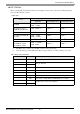

Temperature Controller Driver
GP-Pro EX Device/PLC Connection Manual
3
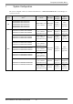
1 System Configuration
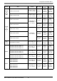
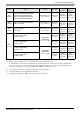
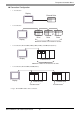
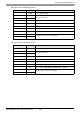
The system configuration in the case when the External Device of RKC INSTRUMENT INC. and the Display are
connected is shown.
Series CPU
*1
Link I/F SIO Type
Setting
Example
Cable
Diagram
CB
CB100-*-5/
CB400-*-5/
CB500-*-5/
CB700-*-5/
CB900-*-5/
Terminal Block on
the controller.
RS422/485
(2 wire)
Setting
Example 1
(page 12)
Cable
Diagram 1
(page 109)
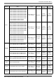
FB
*2
FB900--*1/-
FB400--*1/-
Terminal Block on
the controller.
(Communication 1)
RS232C
Setting
Example 2
(page 14)
Cable
Diagram 2
(page 114)
FB900--*4/-
FB400--*4/-
Terminal Block on
the controller.
(Communication 1)
RS422/485
(4 wire)
Setting
Example 3
(page 16)
Cable
Diagram 10
(page 148)
FB900--*5/-
FB400--*5/-
Terminal Block on
the controller.
(Communication 1)
RS422/485
(2 wire)
Setting
Example 4
(page 18)
Cable
Diagram 1
(page 109)
FB900--*Y/-
FB400--*Y/-
Terminal Block on
the controller.
(Communication 2)
FB900--*X/-
FB400--*X/-
Terminal Block on
the controller.
(Communication 1)
FB900--*W/-
FB400--*W/-
Terminal Block on
the controller.
(Communication 1)
RS232C
Setting
Example 2
(page 14)
Cable
Diagram 2
(page 114)
Terminal Block on
the controller.
(Communication 2)
RS422/485
(2 wire)
Setting
Example 4
(page 18)
Cable
Diagram 1
(page 109)