
Specifications
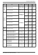


Temperature Controller Driver
GP-Pro EX Device/PLC Connection Manual
5
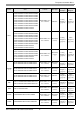
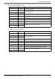
SR Mini
HG
(H-PCP-
A/B)
H-PCP--1N-*
Modular connector
1 on the controller.
RS232C
Setting
Example 38
(page 86)
Cable
Diagram 11
(page 152)
H-PCP--4N-*
Modular connector
on the controller.
RS422/485
(4 wire)
Setting
Example 39
(page 88)
Cable
Diagram 8
(page 140)
SR Mini
HG
(H-PCP-
J)
H-PCP-J-4-D*
COM.PORT1 and
COM.PORT2 on
the controller.
RS422/485
(4 wire)
Setting
Example 20
(page 50)
Cable
Diagram 4
(page 118)
H-PCP-J-5-D*
RS422/485
(2 wire)
Setting
Example 21
(page 52)
Cable
Diagram 5
(page 122)
H-PCP-J-1-D*
COM.PORT3 on
the controller.
RS232C
Setting
Example 22
(page 54)
Cable
Diagram 12
(page 153)
H-PCP-J-4-D*
RS422/485
(4 wire)
Setting
Example 20
(page 50)
Cable
Diagram 6
(page 129)
H-PCP-J-
5-D*
RS422/485
(2 wire)
Setting
Example 21
(page 52)
Cable
Diagram 7
(page 133)
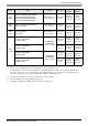
REX-
F9000
F9000--*/
Terminal Block on
the controller.
RS422/485
(2 wire)
Setting
Example 13
(page 36)
Cable
Diagram 1
(page 109)
REX-F
F400-*--1
F700-*--1
F900-*--1
Terminal Block on
the controller.
RS232C
Setting
Example 23
(page 56)
Cable
Diagram 2
(page 114)
F400-*--4
F700-*--4
F900-*--4
Terminal Block on
the controller.
RS422/485
(4 wire)
Setting
Example 24
(page 58)
Cable
Diagram 10
(page 148)
F400-*--5
F700-*--5
F900-*--5
Terminal Block on
the controller.
RS422/485
(2 wire)
Setting
Example 25
(page 60)
Cable
Diagram 1
(page 109)
REX-D
D400-*--4
D700-*--4
D900-*--4
Terminal Block on
the controller.
RS422/485
(4 wire)
Setting
Example 18
(page 46)
Cable
Diagram 3
(page 115)
D100-*--5
D400-
*--5
D700-*--5
D900-*--5
Terminal Block on
the controller.
RS422/485
(2 wire)
Setting
Example 19
(page 48)
Cable
Diagram 1
(page 109)
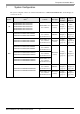
Series CPU
*1
Link I/F SIO Type
Setting
Example
Cable
Diagram