
Specifications


Temperature Controller Driver
GP-Pro EX Device/PLC Connection Manual
6
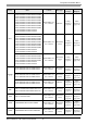
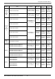
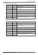
REX-G9
G9-*--1/A
Terminal Block on
the controller.
RS232C
Setting
Example 26
(page 62)
Cable
Diagram 2
(page 114)
G9-*--4/A
Terminal Block on
the controller.
RS422/485
(4 wire)
Setting
Example 27
(page 64)
Cable
Diagram 10
(page 148)
G9-*--2/A
Terminal Block on
the controller.
RS422/485
(2 wire)
Setting
Example 28
(page 66)
Cable
Diagram 9
(page 143)
REX-
P300
P300--*D--1
Terminal Block on
the controller.
RS232C
Setting
Example 29
(page 68)
Cable
Diagram 2
(page 114)
P300--*D--4
Terminal Block on
the controller.
RS422/485
(4 wire)
Setting
Example 30
(page 70)
Cable
Diagram 3
(page 115)
P300--
*D--5
Terminal Block on
the controller.
RS422/485
(2 wire)
Setting
Example 31
(page 72)
Cable
Diagram 1
(page 109)
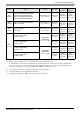
REX-
P250
P250-*--1
Terminal Block on
the controller.
RS232C
Setting
Example 32
(page 74)
Cable
Diagram 2
(page 114)
P250-*--2
Terminal Block on
the controller.
RS422/485
(2 wire)
Setting
Example 33
(page 76)
Cable
Diagram 9
(page 143)
REX-AD
AD410-*---4/CE
Terminal Block on
the controller.
RS422/485
(4 wire)
Setting
Example 34
(page 78)
Cable
Diagram 3
(page 115)
AD410-*---5/CE
Terminal Block on
the controller.
RS422/485
(2 wire)
Setting
Example 35
(page 80)
Cable
Diagram 1
(page 109)
REX-PG
PG410*
-4
Terminal Block on
the controller.
RS422/485
(4 wire)
Setting
Example 36
(page 82)
Cable
Diagram 3
(page 115)
PG410*-5
Terminal Block on
the controller.
RS422/485
(2 wire)
Setting
Example 37
(page 84)
Cable
Diagram 1
(page 109)
AE500 AE500-*-5/
Terminal Block on
the controller.
RS422/485
(2 wire)
Setting
Example 11
(page 32)
Cable
Diagram 1
(page 109)
LE100 LE100-*5-
Terminal Block on
the controller.
RS422/485
(2 wire)
Setting
Example 12
(page 34)
Cable
Diagram 1
(page 109)
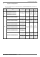
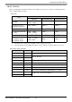
Series CPU
*1
Link I/F SIO Type
Setting
Example
Cable
Diagram