
Specifications


Temperature Controller Driver
GP-Pro EX Device/PLC Connection Manual
7
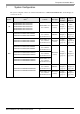
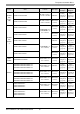
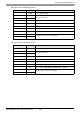
SRZ
(Z-TIO)
Z-TIO-A-/-
Z-TIO-B-/N-
Z-TIO-C-/-
Z-TIO-D-/N-
Terminal Block on
the controller.
RS422/485
(2 wire)
Setting
Example 40
(page 90)
Cable
Diagram 13
(page 154)
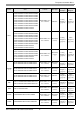
SRZ
(Z-DIO)
Z-DIO-A-/-
Z-DIO-A-/N
Terminal Block on
the controller.
RS422/485
(2 wire)
Setting
Example 41
(page 92)
Cable
Diagram 13
(page 154)
SRZ
(Z-CT)
Z-CT-A/-
Z-CT-A/N
Terminal Block on
the controller.
RS422/485
(2 wire)
Setting
Example 42
(page 94)
Cable
Diagram 13
(page 154)
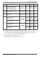
SRZ
(Z-COM)
Z-COM-A-4/
Z-COM-A-4
/N
COM.PORT1
COM.PORT2
on the controller.
RS422/485
(4 wire)
Setting
Example 43
(page 96)
Cable
Diagram 14
(page 161)
Z-COM-A-5/
Z-COM-A-5/N
RS422/485
(2 wire)
Setting
Example 44
(page 98)
Cable
Diagram 15
(page 166)
Z-COM-A-4/
Z-COM-A-4/N
COM.PORT3
COM.PORT4
on the controller
RS422/485
(4 wire)
Setting
Example 45
(page 100)
Cable
Diagram 14
(page 161)
Z-COM-A-5/
Z-COM-A-5/N
RS422/485
(2wire)
Setting
Example 46
(page 102)
Cable
Diagram 15
(page 166)
*1 The mode data "" will vary depending on the type of option.
*2 There are two communication port: Communication 1 and Communication 2.
Communication 1 is used for host communication. Communication 2 is used for intercontroller communication,
but can be also used for host communication. When Communication 2 is used for host communication, it is
necessary to change the protocol of Communication 2 (RKC communication is set).
*3 No memory area number is specified, "Control area" is used as default.
*4 Only Communication 2 supports RS-422 connection.
*5 Only support Single mode, Multi-point mode hasn't been supported.
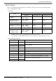
Series CPU
*1
Link I/F SIO Type
Setting
Example
Cable
Diagram