
Datasheet


Page 2016/03/02--Version: 1
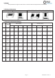
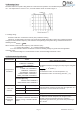
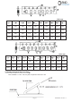
5.0 Derating Curve:
Resistors shall have a power rating based on continuous load operation at an ambient temperature from -55ɗ to
70ć. For temperature in excess of 70ć, the load shall be derate as shown in figure 1
Figure 1
5.1 Voltage rating:
Resistors shall have a rated direct-current (DC) continuous working
Voltage or an approximate sine-wave root-mean-square (RMS) alternating-current (AC) continuous working
voltage at commercial-line frequency and waveform corresponding to the power rating, as determined from the
following formula:
RCWV =
R P u
Where: RCWV commercial-line frequency and waveform (Volt.)
P = power rating (WATT.) R = nominal resistance (OHM)
In no case shall the rated DC or RMS AC continuous working voltage be greater than the applicable
maximum value.
The overload voltage is 2.5 times RCWV or Max. Overload voltage whichever is less.
6.0 Performance Specification:
Characteristic Limits
Test Method
(JIS-C-5201& JIS-C-5202)
˖Temperature
Coefficient
4.8 Natural resistance changes per temp. Degree centigrade
R
2
-R
1
ǘ 10
6
(PPM/ɗ)
R
1
(T
2
-T
1
)
R1: Resistance value at room temperature. (T
1
)
R2: Resistance value at room temp. plus 100ɗ (T
2
)
0201:
1:ูR10:: r400PPM/ɗ
>10:: r200PPM/ɗ
0402~2512:
0.1:ูR烋1ȍ: r800PPM/qC
1:ูRู10:: r400PPM/qC
10:<Rู100:: r200PPM/qC
100ȍ<R<10M:: r100PPM/qC
10MȍʀRู100Mȍ: ±200PPM/qC
Provided Specially:
0603:1ȍ~10ȍ:r200PPM/qC
0805,1206:1ȍ~10ȍ:r100PPM/qC
˖ Short-time
overload
Ʋ0.5%,r1% Ʋ(1%+0.1ȟ)
4.13 Permanent resistance change after the application of a
potential of 2.5 times RCWV for 5 seconds.
Ʋ2%,r5% Ʋ(2%+0.1ȟ)
<50mȍ Apply max Overload current for 0ȟ
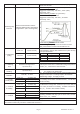
ī Dielectric
withstanding
voltage
No evidence of flashover mechanical
damage, arcing or insulation breaks
down.
4.7 Resistors shall be clamped in the trough of a 90ɗ
metallic v-block and shall be tested at ac potential
respectively specified in the given list of each product type
for 1 minute.