FOR YOUR SAFETY If you smell gas: 1. Open windows. 2. DO NOT try to light any appliance. 3. DO NOT use electrical switches. 4. DO NOT use any telephone in your building. 5. Leave the building. 6. Immediately call your local gas supplier after leaving the building. Follow the gas suppliers instructions. 7. If you cannot reach your gas supplier, call the Fire Department.
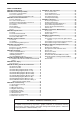
TABLE OF CONTENTS SECTION 1: Heater Safety...................................................... 2 SECTION 2: Installer Responsibility ..................................... 2 2.1 Clearances to Combustibles ........................................ 2 2.2 Corrosive Chemicals.................................................... 2 2.3 National Standards and Applicable Codes .................. 2 SECTION 3: Critical Considerations ..................................... 3 3.1 Basic Information .......................
TABLE OF FIGURES Figure 1: Installation Clearances and Clearances to Combustibles............................................................. 4 Figure 2: Suspension Methods ................................................. 9 Figure 3: Flue and Roof Detail ................................................ 10 Figure 4: Air Intake Terminal Cover......................................... 10 Figure 5: Vertical and Horizontal Flue Termination Type B22 Appliance ..................................................
Product Approval ROBERTS GORDON® appliances have been tested and CE certified as complying with the essential requirements of the Gas Appliance Directive, the Low Voltage Directive, the Electromagnetic Compatibility Directive and the Machinery Directive for use on natural gas and LPG when installed, commissioned and maintained in accordance with these instructions. These instructions refer to appliances designed to operate in the European Union.
COMBAT® CTU UNIT HEATERS INSTALLATION OPERATION AND SERVICE MANUAL SECTION 1: HEATER SAFETY Your Safety is Important to Us! This symbol is used throughout the manual to notify you of possible fire, electrical or burn hazards. Please pay special attention when reading and following the warnings in these sections. Installation, service and annual inspection of heater must be done by a registered installer/contractor qualified in the installation and service of gas-fired heating equipment.
SECTION 3: CRITICAL CONSIDERATIONS SECTION 3: CRITICAL CONSIDERATIONS 3.1 Basic Information CTU heaters have automatic ignition burners for ON/OFF operation only. 3.2 Location and Suspension All models: • Must be installed indoors. • Must be installed in a level position. • May be mounted on a shelf of non-combustible material.
COMBAT® CTU UNIT HEATERS INSTALLATION OPERATION AND SERVICE MANUAL WARNING Fire Hazard Some objects will catch fire or explode when placed close to heater. Keep all flammable objects, liquids and vapours the required distance away from the heater. Failure to follow these instructions can result in death, injury or property damage.
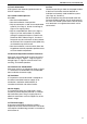
SECTION 4: SPECIFICATIONS SECTION 4: SPECIFICATIONS 4.1 CTUA Top View Heater must be supported at these points from above or below.
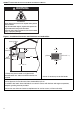
COMBAT® CTU UNIT HEATERS INSTALLATION OPERATION AND SERVICE MANUAL 4.2 CTUB, CTUC and CTUD 1440 K 115 L 679 646 M N N End View End View CTUB/C (All Models) CTUC (All Models) 115 115 646 N P N End View Front View CTUD (And other models fitted with air outlet spigots) CTUD (All Models) Dimension Data - CTUB, CTUC and CTUD Model 22 30 35 40 50 60 75 90 100 115 mm (in) mm (in) mm (in) mm (in) 1026 (40.4) 1026 (40.4) 1026 (40.4) 1026 (40.4) 1026 (40.4) 1026 (40.4) 1076 (42.
SECTION 4: SPECIFICATIONS 4.3 General Technical Data Table Model CTU-22 CTU-30 CTU-35 CTU-40 CTU-50 CTU-60 CTU-75 CTU-90 CTU-100 CTU-115 CTUA With Axial Fan Total Electrical Load W 210 210 210 210 415 415 510 510 745 745 Run Current A 1.0 1.0 1.0 1.0 1.72 1.72 1.9 1.9 3.2 3.2 Start Current A 1.4 1.4 1.4 1.4 2.4 2.4 2.8 2.8 4.5 4.
COMBAT® CTU UNIT HEATERS INSTALLATION OPERATION AND SERVICE MANUAL 4.
SECTION 5: HEATER INSTALLATION SECTION 5: HEATER INSTALLATION 5.1 General Heaters are designed for installation above 2.5 m. These heaters must be installed within the heated space. Duct delivery systems are not permitted with axial fans. 5.2 Handling All CTU heaters are supplied secured to a wooden pallet and shrink wrapped. Use the pallet to support the heater during handling and installation. When handling or supporting the heater from below, ensure that the weight is taken at the support points. 5.
COMBAT® CTU UNIT HEATERS INSTALLATION OPERATION AND SERVICE MANUAL SECTION 6: FLUE INSTALLATION 6.1 Flue Installation Figure 3: Flue and Roof Detail WARNING Flue Terminal Masterflash Soaker Flashing or Rain Collar. Fire Hazard Some objects will catch fire or explode when placed close to heater. Keep all flammable objects, liquids and vapours the required distance away from the heater. Failure to follow these instructions can result in death, injury or property damage.
SECTION 6: FLUE INSTALLATION Figure 5: Vertical and Horizontal Flue Termination - Type B22 Appliance Roof Terminal Masterflash Metal Sleeve (25 mm air gap to Combustible Material) Flue Air Intake Terminal Cover Vertical Option 90° Bend Masterflash Flue Horizontal Option Wall Terminal Figure 6: Vertical and Horizontal Flue Termination - Type C12 C32 & C62 Appliances Roof Terminal Plastic Cup Masterflash Model Concentric Flue Diameter 22-60 Cover (100mm) 150mm 75-115 Cover (130mm) 200mm Manifold Ai
COMBAT® CTU UNIT HEATERS INSTALLATION OPERATION AND SERVICE MANUAL SECTION 7: AIR SUPPLY 7.1 Room Sealed Installation When installed as a room sealed heater, the air for combustion is drawn in from outside the building. It is important to ensure that there is adequate ventilation to provide air for the distribution fan/s. 7.
SECTION 8: OPTIONAL HEATER CONFIGURATIONS SECTION 8: OPTIONAL HEATER CONFIGURATIONS 8.1 Distribution Duct Work for CTUB, CTUC and 8.1.1 CTUD Heaters CTUD Heaters For CTUD heaters, it is essential that the airflow in the duct system is at least that specified in the Data CTUC heaters have the fans enclosed so that the Sheet on Page 6, Section 4.2 and in the correct heater may be connected to inlet ducting.
COMBAT® CTU UNIT HEATERS INSTALLATION OPERATION AND SERVICE MANUAL SECTION 9: GAS PIPING WARNING Fire Hazard Connect gas supply according to Figure 9. Gas can leak if not installed properly. Failure to follow these instructions can result in death, injury or property damage. It is important that the gas supply pipe and the electrical connections do not support any of the heater’s weight. A gas meter is connected to the service pipe by the gas supply company.
SECTION 10: WIRING AND ELECTRICAL INFORMATION SECTION 10: WIRING AND ELECTRICAL INFORMATION 10.1 Electrical Supply 10.2.1 Burner Controls (Thermostat) All heaters need a constant 230 V 50 Hz single Controls to operate the burner must be voltage free contacts connected between terminals 2 & 3 of the phase supply connected to terminals L, N & Earth. main terminal block. Polarity "L & N" must be correct. The voltage between neutral and earth should be 0 and never 10.2.
COMBAT® CTU UNIT HEATERS INSTALLATION OPERATION AND SERVICE MANUAL 10.
SECTION 10: WIRING AND ELECTRICAL INFORMATION 10.
COMBAT® CTU UNIT HEATERS INSTALLATION OPERATION AND SERVICE MANUAL 10.
SECTION 10: WIRING AND ELECTRICAL INFORMATION 10.
COMBAT® CTU UNIT HEATERS INSTALLATION OPERATION AND SERVICE MANUAL 10.
SECTION 10: WIRING AND ELECTRICAL INFORMATION 10.
COMBAT® CTU UNIT HEATERS INSTALLATION OPERATION AND SERVICE MANUAL 10.
SECTION 10: WIRING AND ELECTRICAL INFORMATION 10.
COMBAT® CTU UNIT HEATERS INSTALLATION OPERATION AND SERVICE MANUAL SECTION 11: COMMISSIONING Installation, service, commissioning and annual inspection of the heater must be done by a contractor qualified in the installation and service of gas-fired heating equipment. Read this manual carefully before installation, commissioning, operation, or service of this equipment. All components are accessed via the hinged door secured by a ¼ turn latch.
SECTION 11: COMMISSIONING Figure 10: Automatic Burner Control Box Sequence Burner sequence for Honeywell S4563 or S4565C START RUN CLOSE DOWN Supply 230 V Flue Fan Pressure Switch P NO C 30 Sec. Purge* NC ts** Ignition Spark Start Gas Valve Flame Signal Required Incoming Signals Signals Output By Control *Purge time begins at pressure switch change over. **ts=Safety time (S4563C=3 seconds [alternate 5 seconds]; S4565C=5 seconds) If at any stage the flame fails, the control will go to "lockout".
COMBAT® CTU UNIT HEATERS INSTALLATION OPERATION AND SERVICE MANUAL Figure 12: Gas Valve for Heater (Models 75 - 115) Plug for Main Gas Valve Regulator (Under Cover) Plug for Main Safety Gas Valve Inlet Pressure Gas Inlet Outlet Pressure 11.4.2 Commissioning the Gas Valves (all gases) 11.4.2.1 Check Burner Gas Pressure 1. Loosen the screw cover of the outlet (burner) pressure test point and connect a manometer. 2. With the burner firing, measure the pressure on the manometer.
SECTION 11: COMMISSIONING 11.7 External Controls External controls may include time switch, room thermostat and frost thermostat. Operate each control to ensure that they function correctly. Set the time switch (if fitted) and room thermostat to the users’ requirements. 11.8 Complete the Commissioning Ensure that all covers are fitted correctly and all test points are properly sealed. 11.
COMBAT® CTU UNIT HEATERS INSTALLATION OPERATION AND SERVICE MANUAL SECTION 12: USER INSTRUCTIONS 12.1 User Instructions The CTU heaters are fully automatic and operate from the external controls fitted on site. The only user controls at the heater are the: Burner Lockout Reset Button: See Page 28, Section 12.3.2 Thermostat Limit Thermodisc Reset Button: See Page 28, Section 12.3.1 WARNING 12.3 Common User Controls 12.3.
SECTION 12: USER INSTRUCTIONS 12.4.2 To Turn the Heater Off Set the installed remote controls to the “OFF” position. The burner will turn off immediately. The fan will continue to run for a few minutes. To restart, turn the control used above to “ON”. 12.5 Simple Fault Finding Some possible reasons for the heater not operating are: 1. Gas supply not turned ON. 2. Electricity supply not turned ON. 3. The time and/or temperature controls are not “ON”. 4. The thermostat limit thermodisc may have operated.
COMBAT® CTU UNIT HEATERS INSTALLATION OPERATION AND SERVICE MANUAL SECTION 13: SERVICING 13.1 Servicing Instructions After commissioning, the heater will require maintenance to be carried out annually. If the heater is used in a dirty or dusty area, more frequent maintenance may be necessary. Installation, service and annual inspection of heater must be done by a contractor qualified in the installation and service of gas-fired heating equipment.
SECTION 14: CONVERSION BETWEEN GASES SECTION 14: CONVERSION BETWEEN GASES 14.1 General Conversion between gasses will require a change of burner injectors and the gas valve re-commissioning to the new conditions. 14.2 Burner Conversion Conversion of the burner assembly from one gas to the other is the same for all types of heaters. 1. Remove the burner compartment cover as shown on Page 36, Section 16.2. 2. Remove the connection between the gas valve outlet and the manifold. See Page 35, Section 16.
COMBAT® CTU UNIT HEATERS INSTALLATION OPERATION AND SERVICE MANUAL SECTION 15: TROUBLESHOOTING 15.1 General WARNING Explosion Hazard Installation must be done by a registered installer/ contractor qualified in the installation and service of gas-fired heating equipment or your gas supplier. Failure to follow these instructions can result in death, injury or property damage.
SECTION 15: TROUBLESHOOTING 15.2 Troubleshooting For Automatic Ignition Burner Systems There are two burner controls used: Honeywell S4563C and S4565C. They both have similar operating sequences. To measure flame current, connect a 0 - 50 μA DC meter in series with the flame probe. If the meter reads negative values, then reverse the test leads. WARNING Electrical Shock Hazard Do not touch ignition components. Start Are gas & electrical supplies on? Voltage from ignition components is high.
COMBAT® CTU UNIT HEATERS INSTALLATION OPERATION AND SERVICE MANUAL 15.3 Troubleshooting for Flame Supervision System START Connect a DC ammeter in series with the flame probe. Is the green light on and at least 1 µA DC flame current? Use section 15.1 to trace the fault. No Yes Is there a current flowing in the flame probe circuit with no flame present? Yes Is the connecting lead damaged? Is the flame probe damaged or touching earthed components? Yes Repair or replace as necessary.
SECTION 16: REMOVAL AND REPLACEMENT PARTS SECTION 16: REMOVAL AND REPLACEMENT PARTS See warnings and notes on Page 30, Section 13 before removing or replacing parts. Burner Components All serviceable burner parts are accessed by the door on the right side of the heater. Use a screwdriver to turn the latch 90°. See Page 5, Section 4. 16.1 Gas Valve Remove the gas supply pipe at the heater inlet. 16.1.
COMBAT® CTU UNIT HEATERS INSTALLATION OPERATION AND SERVICE MANUAL 16.2 Burner Compartment The burner compartment is a sealed Burner compartment compartment. Following any work, cover re-seal the compartment with the gas pipe rubber seal fully in place and all Flame probe screws fitted and tight. Viewing port for flame probe Remove flexible air duct from spigot Ignition electrode Viewing port for ignition electrode Remove access plate Rubber Seal Remove screws and pull off burner cover 16.2.
SECTION 16: REMOVAL AND REPLACEMENT PARTS 16.3 Ignition Electrode and Flame Probe Burners Thermostat Limit Thermodisc Flame Probe Remove all burner compartment screws to remove the burner compartment and access the Front View. Flame Probe Remove Screw Burner Compartment Front Views Ignition Electrode Ignition Electrode .120 (3 mm) spark gap Burners To replace the ignition electrode or flame probe, remove the electrical lead and screw. Pull out from mounting.
COMBAT® CTU UNIT HEATERS INSTALLATION OPERATION AND SERVICE MANUAL 16.4 Flue Fan Rear Panel Remove screws securing outlet flange to the flue adapter. Flue Adapter to Flue Fan screws Hole Vent Box Vent Box Screws Outlet Gasket Flue Adapter Flue Fan Disconnect electrical connections at plug in tabs.
SECTION 16: REMOVAL AND REPLACEMENT PARTS 16.5 Pressure Switch Pull off 3 way connector. Spring open plastic clips of mounting cradle. Replace with correct type of pressure switch for model. The pressure switches are colour coded for each pressure setting. WARNING Carbon Monoxide Hazard Use correct pressure switch specified for each model. Use of incorrect pressure switch could cause unsafe condition. Failure to follow these instructions can result in death or serious injury.
COMBAT® CTU UNIT HEATERS INSTALLATION OPERATION AND SERVICE MANUAL 16.6 Ignition Control IT IS IMPORTANT THAT ONLY THE CORRECT IGNITION CONTROL SPECIFIED FOR EACH MODEL TYPE IS USED WHEN REPLACING THESE ITEMS. 16.6.1 S4565C Models 22 to 60 This control plugs onto the gas valve. Pull out 12 pin electrical connection. Pull out ignition cable and flame probe cable noting their positions Release screw securing control to gas valve Refit in reverse. Ensure correct location of ignition and flame probe cables.
SECTION 16: REMOVAL AND REPLACEMENT PARTS • Use only genuine ROBERTS GORDON® replacement parts. The three speed winding connections are: Low speed: White N, Red Live The other two windings are "parked" separately in spare terminals. Medium speed: White N, Blue live. The other two windings are "parked" separately in spare terminals. High speed: White N, Black live. The other two windings are "parked" separately in spare terminals.
SECTION 16: REMOVAL AND REPLACEMENT PARTS Attach this information to the wall near the ROBERTS GORDON® heater ® Read the Installation, Commissioning, Operation and Service Manual thoroughly before installation, operation or service. WARNING OPERATING INSTRUCTIONS 1. STOP! Read all safety instructions on this information sheet. 2. Open the manual gas valve in the heater supply line. 3. Turn on electric power to the heater. 4. Set the thermostat to desired setting (above ambient temperature).