
User Manual


2
Programming Steps and Display Mode
The ETC can be programmed in four simple steps using the LCD display
and the three keys on the face of the control.
Step 1 To start programming, press the SET key once to access the
Fahrenheit/Celsius mode. The display will show the current
status, either F for degrees Fahrenheit or C for degrees
Celsius. Then press either the up Ç or down È arrow key
to toggle between the F or C designaon.
Step 2 Press the SET key again to access the setpoint. The LCD will
display the current setpoint and the S1 annunciator will
be blinking on and o to indicate that the control is in the
setpoint mode. Then press either the up Ç key to increase
or the down È key to decrease the setpoint to the desired
temperature.
Step 3 Press the SET key again to access the dierenal.
The LCD will display the current dierenal and the DIF 1
annunciator will be blinking on and o to indicate that the
control is in the dierenal mode. Then press either the
up Ç key to increase or the down È key to decrease the
dierenal to the desired seng.
Step 4 Press the SET key again to access the cooling or heang mode.
The LCD will display the current mode, either C1 for cooling
or H1 for heang. Then press either the up Ç or down È key
to toggle between the C1 or H1 designaon.
Step 5 Press the SET key again to access the An-short Cycle
Compressor Delay when in Cooling Mode. Press the up Ç or
down È keys to set the delay from 1 to 20 minutes. Press
SET key again to nish the programming.
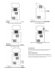
Figure 1: Setpoint and Dierenal Sengs. Diagram indicates relay
on and o points in either the heang or cooling modes
Lockout Switch
The ETC is provided with a lockout switch to prevent tampering by
unauthorized personnel. When placed in the LOCK posion, the keypad
is disabled and no changes to the sengs can be made. When placed
in the UNLOCK posion, the keypad will funcon normally.
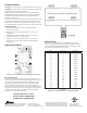
To access the lockout switch, disconnect the power supply and open
the control. The switch is located on the inside cover about 2 inches
above the boom. (See Figure 2). To disable the keypad, slide the
switch to the le LOCK posion. To enable the keypad, slide the switch
to the right UNLOCK posion. All ETC controls are shipped with this
switch in the UNLOCK posion.
LOCKOUT :
LOCK
UNLOCK
USE COPPER CONDUCTORS ONLY
DISPLAY CODES
F FAHRENHEIT
C CELSIUS
H1 HEAT STAGE 1
C1 COOL STAGE 1
EP PROBE FAILURE/
OUT OF RANGE
EE EEPROM FAILURE
E1 IMPROPER KEY
E2 MEMORY ERROR
RELAY RATINGS N.O /N.C.
VAC
120
208/240
LRA
96/34.8 48/17.4
FLA
16/5.8 8/2.9
15/5.8 8/2.9
RES A
PILOT DUTY 125VA
1
THERMOSTATS
52N8
Step Annunciator Descripon Display
1 F or C Fahrenheit or Celsius
Scale
2 S1 (blinking) Setpoint
Temperature
3 DIF 1(blinking) Dierenal
Temperature
4 C1/H1 Cooling or
Heang Mode
5 D1 Cooling Delay
Set to 1-20 Minutes
Figure 2: Lockout Switch
NOTE: The ETC will automacally end programming if no keys are
depressed for a period of thirty seconds. Any sengs that have
been input to the control will be accepted at that point.
All control sengs are retained in non-volale memory if power to
ETC is interrupted for any reason. Re-programming is not necessary
aer power outages or disconnects unless dierent control sengs
are required.