
User Manual


4
CONTROL WIRING
General
• All wiring should conform to the Naonal Electric Code and local
regulaons.
• The total electrical load must not exceed the maximum rang of the
control (see Specicaons).
• Use copper conductors only.
• Electrical leads should not be taut; allow slack for temperature
change and vibraon.
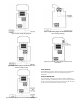
Input and Output Wiring
For typical wiring diagrams, refer to Figures 4, 5 and 6. All connecons
are made to the power (lower) circuit board. When using the 24V AC
powered models, the 24V AC input lines must enter through the
sidewall of the case. Refer to Figure 3 for locaon of the entry hole and
Figure 7 for wiring.
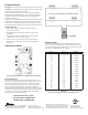
Analog Output
ETC models are available with an oponal 0 to 10 volt analog output.
This signal is a linear representaon of the sensor temperature with
0 volts = -30°F and 10 volts = 220°F. See gure 8 for wiring informaon
and Figure 3 for locaon of the entry hole. The reference for this output
is designated by the ”-” symbol on the wiring diagram. The output
signal is designated by the ”+” symbol.
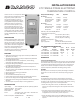
Figure 3: Dimensions (in Inches)
CONTROL MOUNTING
Mount the ETC to a wall or any at surface using a combinaon of any
two or more of the sloed holes located on the back of the control
case. The control’s components are not posion sensive, but should
be mounted so that they can be easily wired and adjusted. Avoid
excessive condions of moisture, dirt, dust and corrosive atmosphere.
The ETC has provisions for 1/2 inch conduit connecons. The conduit
hub should be secured to the conduit before securing the hub to the
plasc housing of the control. When using the conduit entry in the rear
of the case, a standard plug should be inserted into the conduit hole
in the boom. Cauon should be exercised not to damage the control
circuit board or wiring when installing a conduit connector.
ANTI-SHORT CYCLE COMPRESSOR DELAY
When the unit is congured for cooling and there is a call for cooling,
the relay will not acvate unl the An-short Cycle Compressor
Delay is sased. During an An-short Cycle Compressor Delay, the
temperature will alternate with Cd (Cooling Delay) to indicate the Relay
On is delayed.