
User Manual
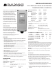


5
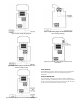
Figure 5: Typical Wiring Diagram for 24V AC Power Input
and Line Voltage Switching.
Figure 7: Typical Wiring Diagram for 24V AC Power Input
and Line Voltage Switching.
Figure 4: Typical Voltage Wiring Diagram.
Figure 8: 0-10 V Analog Output Located on Power (Lower)
Circuit Board.
Figure 6: Dierent Voltage to Control and Dierent Voltage Load.
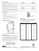
FIELD REPAIRS
Field calibrang or repairs to the ETC control must not be aempted.
Sensors and replacement controls are available through Ranco
wholesalers.
SENSOR MOUNTING
For space sensing, mount the sensor where it will be unaected by
heat/cool discharge or radiated heat sources. Spot sensing requires the
sensor to be in good contact with the surface being sensed. The sensor
can be inserted in a bulb well for immersion sensing.