
Installation Manual

5
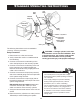
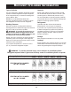
The following instructions are for a standard or
“common” recovery procedure.
Setup Procedure
1. Place the unit on a at, level surface.
2. Verify a clean lter screen is installed behind
the inlet tting.
3. Connect a hose from the outlet tting of the
unit to the liquid port on the recovery cylinder.
4. Connect a hose from the inlet tting of the unit
to the output port of a manifold gauge set.
Robinair recommends using a sight glass and
a lter / drier in this line.
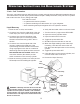
5. Connect a hose from the liquid (low pressure)
side of the manifold gauge set to the liquid side
of the system being serviced.
6. Connect a hose from the vapor (high) side of
the manifold gauge set to the vapor side of the
system being serviced.
RG6 with SK-5001 kit installed: Attach tank
connection harness (No. 549977) to oat
switch connection on the recovery cylinder.
7. Verify the inlet and outlet valves on the unit are
closed.
8. Place the recovery cylinder on a scale (such as
TIF9010A) to avoid overlling the cylinder.
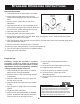
Standard oPerating inStructionS
Manifold
Gauge Set
System Being
Serviced
Inlet
Fitting
Outlet
Fitting
Float Switch
Connection
(RG6 w/ SK-5001
kit installed)
Liquid
Vapor
Scale
Recovery
Cylinder
Sight
Glass
Filter / Drier
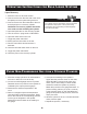
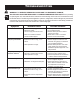
Tech Tips
The unit will perform at its peak when voltage
entering the machine (while operating) is between
115—122 VAC.
Lower supply voltages may result in difculty
starting under high head pressure, reduced
performance, and / or motor overheating.
Use an outlet that does not have other applicances
(such as lights, machines, etc.) plugged into it.
Do not use an extension cord unless needed. If
an extension cord is used, it must be 14 AWG
minimum and as short as possible to reduce
voltage drops.
WARNING : A storage cylinder is full when
it reaches 80% volume. DO NOT OVERFILL. Due
to liquid expansion, the cylinder could explode
if lled to more than 80% volume, possibly
causing personal injury and equipment damage.
Liquid Port