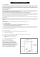
Robinson Willey D269 Handbook Contemporary, Charisma, Classic (BRASS OR CHROME with COAL EFFECT) Desire ( STAINLESS STEEL with PEBBLE EFFECT ) Cat I2H G20 at 20mbar For use in GB and IE. The data plate is located at the bottom left hand side of the firebox This handbook contains both Installer and user information and must be left with the owner.
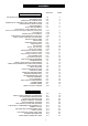
CONTENTS SECTION PAGE INSTALLATION SECTION INTRODUCTION AND GENERAL REQUIREMENTS TECHNICAL DATA CONTENTS OF SCREW PACK CONTENTS OF CERAMIC FUEL COMPONENT PACK CONDITIONS OF INSTALLATION SITING GENERAL FLUES AND CHIMNEYS Brick Chimney, 178mm diameter (7 inch) Stone or Lined Flue and 125mm diameter (5 inch) Flue Pre-Cast Flue Rebated Surround Installation Metal Fluebox 125mm diameter (5 inch) Flues SHELF HEIGHT AND SIDE CLEARANCES INSTALLATION OF FIRE UNPACKING PREPARATION OF FIRE Spigot Restrictor Fender
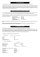
1.0 INTRODUCTION NO COMPONENT OF THIS FIRE IS MANUFACTURED FROM ASBESTOS OR ASBESTOS RELATED PRODUCTS. This appliance is an open fronted inset live fuel effect gas fire, it is suitable for use with Brick Chimneys(including lined), twin walled or insulated Metal/Pre-fabricated Flues of 125mm minimum diameter and Flueboxes conforming to the constructional requirements of BS 715 and Pre-Cast Flue applications. It is fitted with a combined flame supervision and oxygen depletion monitoring device.
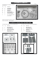
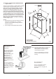
3.0 CONTENTS OF SCREW PACK Fig. 1. The contents of the screw pack are as follows (refer to Fig 1.): Key Qty Description A B C D E F G H J 2 2 2 4 4 4 4 1 2 Fixing Cables Cable Adaptors Grub Screws Cable Eyelets Wall Plugs Fire Fixing Screws No 6 Self Tapping Screws Gas Inlet Grommet Cable Tensioning Bolts K 2 No. 8 Self Tapping Screws (not illustrated) J H A E I G C B D F NOTE: Also included in the pack is the ‘Spacer’ required to fit the fire to some pre-cast flues - see section 5.2.
.0 CONDITIONS OF INSTALLATION 5.1 SITING GENERAL This fire is suitable for hearth mounting only on a non-combustible hearth at least 13mm thick and measuring at least 630mm wide by 330mm deep, the periphery of which should preferably be 50mm above the floor level in order to discourage the placing of carpets or rugs over it. It MUST NOT be fitted directly on a combustible wall. The fire should be installed so that no part of a combustible wall i.e.
5.2.2 PRE-CAST FLUE OF MINIMUM SIZE (Fig. 4) PRE-CAST FLUE INSTALLATION This fire can be installed into a properly constructed pre-cast flue conforming to B.S. 1289 : 1975 or B.S. 1289 : Part 1 : 1986 or B.S. 1289 : Part 2 : 1989 of at least 3 metres effective height and having flueways of at least 198mm by 67mm or equivalent cross-sectional area with no dimension less than 63mm. The fireplace opening width must be between a maximum 457mm and a minimum 406mm.
5.2.3 REBATED SURROUND INSTALLATION When fitting the fire to a pre-cast flue it is possible to use a 152mm deep rebated surround. Two optional extras are required as follows: Part Number Closure Plate Spigot 989571 989568 Fit the closure plate to the wall ensuring that a good seal is made between the plate and the wall. The plate has been designed to sit on the floor behind the rebated surround or hearth.
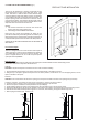
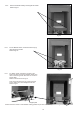
5.2.4 METAL FLUE BOX/125mm DIAMETER FLUES (Figs. 8 and 9) 2. 45 98 UE E FL NTR CE 31 7 7 610 NOTES: 1. If the flat area around the front opening of the box is less than as specified in Fig. 3, it may be necessary to use additional sealing material to achieve a good seal. 125 I/D 560 This fire may be installed in a double walled or insulated metal box built to the requirements of B.S. 715 e.g. Selkirk, Product Code Number 0404905, using our fixing kit G.C. Number 159 634 Part Number 992137.
5.3 SHELF HEIGHT AND SIDE CLEARANCES The fire may be fitted beneath a shelf. See ‘User section’ (PAGE 18). 6.0 INSTALLATION OF FIRE 6.1 UNPACKING The fire is packed with the rear brick board already fitted in position. When unpacking refer to the check list to ensure that all of the components are present and undamaged. Remove the top fitment from the carton - this contains accessories for the ‘Pebble version’. . Remove the spacer . Lift the carton surround clear of the fire.
6.2.2 Remove the fender mask by removing the two screws. Refer to Fig 11a. Fig 11a. 6.2.3 For the ‘Manual’ version, remove the burner tray by removing the two screws. Refer to Fig 11b. Fig 11b. 6.2.4 For ‘Slider’ version, release the ‘link arm’ at the lower R.H. Side. Set control to ‘Medium setting’ and remove connecting screw. Allow ‘link arm’ to rest on support plate. Refer to ‘enhanced view’ of Fig 12. Then remove the burner tray by removing the two screws, taking care not to damage the ‘link arm’.
6.3 METHOD OF INSTALLATION There are two methods for securing the fire to the wall which are: (a) Fixing by tension cable. (b) Screwing the fire directly to the wall. It is recommended, where drilling holes in the front face of the fireplace surround is unacceptable or otherwise risky e.g. a marble surround, that fixing by tension cable is employed.
6.4 GAS CONNECTION NOTE: The appliance must be connected to gas with rigid or semi-rigid tubing, from either the right or left hand side, or by concealed connection (see below). The supply pipe to the fire should be installed so that it is easy to remove the fire from the opening during servicing. An isolation inlet elbow is fitted to the burner assembly for isolation of the fire for servicing at a later date. Fig 16.
7.0 COMMISSIONING 7.1 INSTALL FUEL EFFECT COMPONENTS The base ceramic matrix, side cheeks and fuel effect components are illustrated in Fig 2. The fire is supplied with the rear brick effect panel already fitted as illustrated in Fig 11. Unpack the pack containing the ceramic fuel effect components and check that these are undamaged and complete. Install the fuel effect components as detailed on pages 21 and 22/23 of the Users section of this booklet.
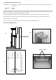
7.3 TEST FOR SPILLAGE A test for spillage must be made before the installed fire is left with the user. This is carried out in the following manner. Light the fire and leave at HIGH rate. Close all the doors and windows in the room and after the fire has been alight for five minutes insert a lighted smoke match into the notch in the canopy in a horizontal direction with the tip 50 mm inside the canopy (See Fig. 20). Hold the match in a metal tube.
8.0 INSTRUCT USER Refer to Users Instructions Make sure the user understands the following: (a) How to light and operate the fire. (b) The fire can be lit with a match or taper in the event of failure of the spark ignition. (c) Demonstrate the removal and replacement of the coals, drawing attention to keeping the FOUR FRONT coals separate. Advise on the need to clean these regularly. (d) Advise that for safe and efficient operation, the fire should be serviced annually by aGas Safe registered Engineer.
9.4 PILOT ASSEMBLY The pilot is an atmosphere sensing device and must be replaced as a complete unit. Repair must not be undertaken. NOTE: If the fire keeps going out or exhibits signs of nuisance shut off, check the operation of the pilot as follows:(a) (b) (c) (d) (e) (f ) Check the pilot lint trap for blockage. Remove any lint present. Inspect the pilot flame, if suspect check the gas supply. Inspect the filter in the pilot outlet of the tap. Clear blockage if necessary.
10.0 HINTS ON FAULT FINDING The following are possible fault conditions. Check the items mentioned and repair or replace parts as necessary. The list is not exhaustive but a fair outline of possible faults. 1. No Spark (a) (b) (c) 2. Spark but the pilot does not light. (a) (b) (c) (d) 3. (b) Check for linting of the pilot lint trap filter(Steel gauze fitted around the body of the pilot burner) and the aeration hole under the filter. Pilot starvation due to partial blockage.
USER SECTION 11.0 USER INFORMATION This fire must be installed and serviced regularly in accordance with the Gas Safety (Installation and Use) Regulations and the rules in force by a competent person e.g. a Gas Safe registered Engineer. Where solid fuel has been used the chimney must be swept before installation. This fire must be installed in accordance with the installation instructions.
12 CLEANING AND SIMPLE MAINTENANCE All cleaning should be carried out when the fire is cold. Generally the fire will only need dusting. Any painted surface or metal part should be cleaned with a damp cloth only. Never use any abrasive materials or metal polish on painted surfaces or metal parts. FUEL EFFECT COMPONENTS This product uses fuel effect pieces containing Refractory Ceramic Fibre (RCF), which are man-made vitreous silicate fibres.
13.0 OPERATING INFORMATION WARNING: If the flames are found to be extinguished and the control is not in the OFF position, the control should be returned to the OFF position and no attempt should be made to light the gas until at least 3 minutes have elapsed. WARNING: If you want to relight a hot fire wait 3 minutes before doing so. NOTE: When you turn a hot fire off there may be some popping noise for a short period. This should not cause alarm. 13.
14.0 INSTALLATION OF FUEL EFFECT COMPONENTS The Fuel Effect pack contents are illustrated in Figs 2a & 2b. The fire is supplied with the rear brick effect panel already fitted. This procedure is the same for both pebble and coal versions (coal illustrated). Unpack the Fuel Effect components and check that these are undamaged. DO NOT INSTALL THE FIRE WITH BROKEN OR MISSING FUEL EFFECT COMPONENTS. USE ONLY THE FUEL EFFECT COMPONENTS SUPPLIED WITH THE FIRE.
14.1 PEBBLE LAYOUT O O O G H Position 3 pebbles (O) on each of the platforms on the centre coal. Arrange pebbles (G), (H), and (A) along the front of the base ceramic matrix as shown in fig 26a. A Fig 26a I K O O O L J H G A Support pebbles (I) and (K) on the (O) pebbles. Locate (J) and (L) on either side of the fuel bed (See fig 27a). Fig 27a F D N M C E B J Position pebbles (B) and (E), then locate (C) centrally on the bed.
14.3 COAL LAYOUT Position the four separately packed coals in the corresponding indentations on the front edge of the base ceramic matrix. See fig. 26b. NOTE: On later removal of loose coals, keep separate the four front coals (see fig 26b) for correct replacement. Fig 26b Position a coal on each of the platforms on the center ceramic as shown in Fig. 27b. Fig 27b Place a coal on either side, resting on the side of the base ceramic matrix and the loose coal beside it.
14.4 LIGHTING WITH A TAPER In the unlikely event of failure of the ignition spark the fire can be lit with a taper or a long spill. Remove the ash-pan and fender. You should be able to see the pilot burner just below the base ceramic matrix, to the left of centre (see Fig 30b). Light your taper and apply it to the pilot burner. Turn the control knob to the pilot position and fully depress, or for slider version depress the knob to pilot position.