Courier V.Everything External Modem: Getting Started FINAL 4/96 p/n 1.024.492 1996 U.S. Robotics Access Corp. 8100 North McCormick Blvd.
U.S. Robotics and the U.S. Robotics logo are registered trademarks of U.S. Robotics Access Corp. V.Fast Class and V.FC are trademarks of Rockwell International. Any trademarks, tradenames, service marks or service names owned or registered by any other company and used in this manual are the property of their respective companies. 1996 U.S. Robotics Access Corp. 8100 N. McCormick Blvd.
Table of Contents About This Manual iii We Welcome Your Suggestions.............................................................iii Chapter 1 The Courier 1-1 Courier Controls, Displays, and Connectors.....................................1-3 Status Indicators ....................................................................................1-4 Features ...................................................................................................1-5 Chapter 2 Installing the Courier 2-1 What You Need...
Appendix B Technical Specifications B-1 Standards Compatibility...................................................................... B-1 Appendix C Warranty and Notices C-1 Limited Warranty .................................................................................C-1 Notices....................................................................................................
About This Manual This manual explains how to set up and start using your Courier V.Everything External Modem. Refer to the Command Reference manual, also included with the Courier, for detailed information about using advanced features. We Welcome Your Suggestions We’ve made every effort to provide you with useful, accurate information. If you have any comments or suggestions about these materials, please let us know. Voicemail: (847) 933-5200 Email: sysdocs@usr.
Chapter 1 The Courier The Courier V.Everything External Modem makes any computer or terminal with an EIA/RS-232 serial port (or a Macintosh serial port) capable of exchanging data with modems or fax machines over standard, analog telephone lines at speeds of up to 33.6 Kbps.
Calling Online Services Each online service, such as America Online or CompuServe, provides its own customized communications software package. A couple of these packages are included with the Courier. These packages do the dialing and guide you through the steps of registration. Accessing Corporate Networks Remotely Dialing in to a remote network requires remote access software. When you dial in to a network, the software makes your remote computer appear to the network as locally attached.
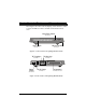
Courier Controls, Displays, and Connectors These figures show the controls, displays, and connectors on the Courier and indicate where to find more information about each. Voice/Data Switch SEE PAGE 4-2 HS AA CD NS RD SD DTR MR RTS CTS SYNC ARQ/ FAX Status LEDs VOICE/DATA COURIER V.EVERYTHING with V.34 Volume Control SEE PAGE 1-4 SEE PAGE 4-1 Figure 1-1. The Courier V.Everything Modem (Front).
Status Indicators The Courier displays its status using 12 light-emitting diodes (LEDs) that are visible from the front. Table 1-1. The Courier's Status Indicators. HS On Off AA On Blinking Off CD On Off OH On Off RD Flashing Off SD Flashing Off TR On Off MR On Flashing Off RS On Off CS On Off High Speed 4800 bps or faster connection. Once on, remains on until reset. The Courier has not made a 4800 bps or faster connection since last reset. Auto Answer Status Auto-answer on. Incoming call detected.
SYN On Blinking Off ARQ/FAX On Flashing Blinking Off Synchronous Status The Courier is in synchronous mode. Dial security is active. The Courier is not in synchronous mode/dial security not active. Error Correction/Fax Error correction is active. The Courier is retransmitting data to the remote modem. The Courier is in fax mode. Error correction not active/not retransmitting data/not in fax mode. Features 33.6 Kbps Connectivity The Courier contains software that enables 31.2 and 33.
connecting also runs software that supports speeds above 28.8 Kbps. If you are curious about the role that line quality plays in attaining and maintaining high speed connections, and want to learn what you can do to improve connections, request the following document from our Fax on Demand service: Phone Line Quality and High Speed Connections. The Fax on Demand number is (800) 762-6163. V.Everything The Courier provides full support of the V.34 standard, V.Fast Class, V.
Remote Configuration and Diagnostics You can remotely configure and test the Courier. If you are a network administrator supporting remote users, this feature can save you time and money. Refer to Chapter 8, Remote Access, in the Courier Modems Command Reference manual. Adaptive Speed Leveling (ASL) Couriers monitor line conditions while connected, and fall back to the next lower speed—for example, 19.2K, then 16.8K in V.32terbo mode—if conditions are poor.
Carrier Loss Redial If you enable the carrier loss redial feature, the Courier will automatically redial the last number it dialed if carrier is lost (for example, if there is trouble on the line or if the remote modem hangs up). This feature is useful for dialed-line connections that operate unattended. See Chapter 3, Dialing, Answering, and Hanging Up, in the Courier Modems Command Reference manual.
Chapter 2 Installing the Courier What You Need A Computer or Terminal with a Serial Port The Courier is compatible with any computer or terminal that provides a serial port with an EIA-232 interface. See Appendix A, The Serial Port, for details. For top performance, your serial port must support speeds of 115.2 Kbps. For IBM-compatible PCs, make sure your computer has a 16C550 UART. Check your computer’s documentation for details.
A Serial Cable Because there are a variety of connector types that different computers require, a serial cable is not provided with the Courier. See the next section, Choosing a Serial Cable, for guidelines. Choosing a Serial Cable 1 Check the back of your computer for a serial port. Serial ports may be labeled with the word COM or RS-232 or with symbols such as IOIOI, , or . Refer to your computer’s documentation to be sure. DB-25, Male DB-9, Male 8-pin Mini-DIN (Macintosh) Figure 2-1.
Package Contents ♦ ♦ ♦ ♦ ♦ ♦ ♦ The Courier Power adapter Phone cable Quick reference card Customer support services card DOS/ Windows communications software package A Command Reference manual and this Getting Started manual Figure 2-2. Contents of the Courier Package.
Installing the Courier 1 Connect the male DB-25 end of your serial cable to the Courier and the other end to a serial port on your computer. 2 If you are connecting the Courier to an IBM-compatible PC, note the number of the serial port to which you connect the Courier. If your serial ports are lettered instead of numbered, A is COM1 and B is COM2. 3 Connect one end of the phone cable to the wall jack and the other end to the Courier port labeled JACK.
Table 2-1. DIP Switch Settings.
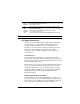
Powering On the Courier Flip the power switch at the back right corner of the Courier. Watch the LED indicators at the front. HS AA CD NS RD SD TR MR RS CS SYN ARQ/ FAX VOICE/DATA COURIER V.EVERYTHING with V.34 Figure 2-4. Normal Appearance of the Courier's LEDs When Not Attached to a Computer. HS AA CD NS RD SD TR MR RS CS SYN ARQ/ FAX VOICE/DATA COURIER V.EVERYTHING with V.34 Figure 2-5.
Chapter 3 Communicating with the Courier After you’ve connected the Courier to a serial port and powered the Courier on, you need to make sure that your computer can send commands to the Courier. Once you’re sure that your computer can communicate with the Courier, you’re ready to start making or taking calls! The methods of verifying communication with a modem vary depending on the operating system your computer uses. Windows 95 Windows 3.
Getting the INF File 1 Power on your computer with the modem installed. As Windows 95 loads, it presents a New Hardware Found panel. Select Standard Modem. 2 Start a communications software package (such as HyperTerminal, which is included with Windows 95) and dial the U.S. Robotics BBS at (847) 982-5092. Go to File directories, then 5) U.S. Robotics Courier. Download the MDMUSRCR.INF file. Or, ftp://ftp.usr.com/SYS/PCB/dl05 and get MDMUSRCR.INF.
Making Windows 95 Auto-Detect Your Courier 1 Click Start | Settings | Control Panel and then double-click Modems. Remove the Standard Modem. 2 Then click Add. 3 At the Install New Modem panel, click Next. Windows 95 will auto-detect your Courier and install the appropriate support. Windows 95 Dial-Up Networking: Internet Access This section explains how to set up the Courier for accessing the Internet using Windows 95 Dial-Up Networking. You can also use Dial-Up Networking for accessing remote LANs.
Add Dial-Up TCP/IP Support. 5 Click Start | Settings | Control Panel. 6 From the Control Panel, double-click on Network. If TCP/IP -> Dial-Up Adapter is listed, go to step 8. If not, continue with step 7. 7 Select Add… | Protocol | Microsoft | TCP/IP | OK. Insert your Windows 95 Setup diskette or CD-ROM when you are prompted, and Windows 95 will install TCP/IP protocol support. Customize the TCP/IP Settings. 8 Click Start | Settings | Control Panel.
Set Up a Connection to Your Internet Service Provider. 11 Click Start | Programs | Accessories | Dial-Up Networking. 12 Double-click Make New Connection. Type a name for the connection, then click Next >. Type a phone number for the connection, then click Next >. You should see a message indicating that a new connection was created successfully. Click Finish. 13 From the Dial-Up Networking window, put the cursor over your new icon and click the right mouse button.
DOS Because there is no communications software built in to DOS, you must install and run a third-party communications software package in order to operate the Courier. The Quick Link II diskette, which is included in the package with the Courier, contains a DOS version of the software as well as a Windows version. You must choose the COM port to which the Courier is attached in whatever communications software package you are using.
Mac OS Be sure you’re using a hardware handshaking cable to connect the Courier to the Macintosh. Also, if you won’t be using AppleTalk Remote Access (ARA), then set AppleTalk to Inactive (in Chooser). Otherwise ARA may interfere with your communcations software. As a general rule, set DIP switches 1, 3, 5, and 8 ON, and use AT&F1 as your modem initialization string.
Start Windows Terminal to verify that NT can communicate with the Courier. Select the COM port to which the Courier is connected. You should be able to send AT and get an OK response. From the Control Panel, double-click Network. The Network Settings window appears. Scroll down the list of Installed Network Software and select Remote Access Service. Click Configure… The Remote Access Setup windows appears. Click Add… 3-8 Courier V.
Select the port to which the Courier is connected. When you click OK, Remote Access setup asks you if you would like it to try to detect the modem connected to the port. Click Cancel to select the Courier from a list. Select US Robotics Courier V.34, and then click OK and exit from Network setup. When you’re prompted to restart NT, click Don’t Restart Now. Then, from Program Manager, click File | Shutdown. When NT shuts down, power your computer off and then on again.
UNIX/Linux/AIX If the Courier will be answering, set DIP switch 3 OFF; 4 and 8 ON. Linux has a built-in communications software package called minicom. By default, minicom is located in the usr/bin directory. For instructions about how to set up your UNIX, Linux, or AIX communications software package, call our fax-on-demand service (at 800-762-6163 or 847-676-1598) or our BBS (at 847-9825092). Request document 10000 for a list of our technical support documents.
Testing the Courier Use any communications software package for this test. Quick Link II Fax is used as an example. Quick Link II Fax 1 Install and then start Quick Link. 2 Click Setup | Line Settings… Make the following settings. If you are using a computer with a serial port that cannot support high speeds, choose 19200. Then click OK. 3 Click Setup | Modem Setup… Select the Comm. Port to which the Courier is attached. Click OK. 4 In the terminal window, type AT .
NOTE: If you need to dial 9 to get an outside line, dial as in this example: ATDT9,18479825092 . If you want to disable call waiting for this call, in most areas, dial *70 before you dial the phone number, for example, ATDT*70,18479825092 . The following screens are what you should see when you dial the BBS.
Chapter 4 Other Features This chapter explains how to use features specific to the Courier V.Everything External Modem, including the volume control, the Voice/Data switch, and MI/MIC operations. Voice/Data Switch HS AA CD NS RD SD DTR MR RTS CTS SYNC ARQ/ FAX VOICE/DATA COURIER V.EVERYTHING with V.34 Volume Control Volume Control The volume control is located under the right front of the Courier. Slide the control toward the front of the Courier to increase the volume.
The Voice/Data Switch The Voice/Data switch allows you to alternate voice and data over the same connection. You call the remote user by telephone, then you each press the Voice/Data switch on the Courier. After you’re finished sending and receiving files, press the Voice/Data switch to return to voice. You can accomplish the same function by sending AT commands, and you can also assign a different function to the Voice/Data switch if you don’t plan to use it for alternating voice and data.
Sending ATS32=2 tells the Courier to go on line and send ATA when you press the Voice/Data switch. NOTE: If you’ve stored a command string (using &ZC=s), the Courier will default to S32=9, which executes the stored command string when you push the Voice/Data switch. 3 Call the remote user (make a voice call) or have them call you. You must the phone that is attached to the Courier’s PHONE port.
2 If you are to originate the connection, type the following command: ATD NOTE: Be sure the modem is not set to X2, X4, X6 or X7, or it will return the NO DIAL TONE result code and hang up. 3 The remote user should type the answer command: ATA 4 If the remote modem also has handset exclusion, leave both phones off hook in case you wish to switch back again to voice after your data transfer.
Table 4-1. Voice/Data Switch Commands.
Getting Information About Calls Here are the commands that provide detailed information about your current settings and current and last calls. To get call-in-progress data and current settings while you are on line, set DIP switch 9 OFF and then send ATZ (or power the Courier off and then on). Alternatively, you can send ATS14.0=0 , but be aware that the DIP switch setting will override your setting at power on or reset (even if you add &W to write the command to NVRAM).
Last Call Last-dialed number Disconnect reason Speed Duration Modulation Error control protocol Compression type ATI4 — Last Dialed # ATI6 — Disconnect Reason is ATI6 — Speed ATI6 — Last Call ATI11 — Modulation ATI6 — Protocol ATI6 — Compression MI/MIC Operations Couriers are shipped with MI/MIC disabled, that is, for normal use. Mode Indicate/Mode Indicate Common (MI/MIC) closure is required for some applications where existing hardware, such as a PBX, does the dialing.
7 Remove the modem (printed circuit board), carefully easing the voice/data switch out of its opening in the front panel. 8 Locate jumpers J4 and J6. J4 J6 MI/MIC Jumpers Figure 4-1. Location of the MI/MIC Jumpers. 9 Set the jumpers as shown: To From J4 J6 10 Replace the modem and reconnect the J4 J6 cables. CAUTION: When you power on the modem there will be potentially hazardous voltage, particularly near the phone jacks. Do not touch the board when the power is on. 11 Power on the modem.
12 When you are sure the equipment is working correctly, reassemble the Courier. Troubleshooting If the Courier does not respond to MI/MIC closure, or if the Courier fails to go back on hook when the computer or terminal drops the Data Terminal Ready (DTR) signal, your phone equipment probably reverses MI/MIC polarity. You can solve this problem by reversing the modem's MI/MIC wiring. Do this by resetting the two jumpers on the printed circuit board. Follow the steps from the previous section.
Chapter 5 Setups for Common Windows Software Packages If you are running one of the following software packages, follow the steps given to configure it for use with the Courier. America Online v2.0 NetManage Chameleon v4.5 pcAnywhere v2.0 for Windows ProComm Plus v2.0 for Windows Prodigy Trumpet Winsock WinCIM (for CompuServe) WinFax Pro 4.0 These instructions are valid as of the printing of this manual and may not apply to future releases of the software packages.
4 The following window will appear. Change the Setup Modem String to match: 5 Select OK, then OK, then OK. NetManage Chameleon 4.5 You should know in advance which Internet service provider (for example, PSINet or NETCOM) you will be using. NetManage provides a number of configuration templates for many popular Internet service providers. The settings recommended here are the Courier-specific ones only. 1 Click Setup | Communications | Port.
2 Click Setup | Communications | Modem. Select U.S. Robotics Courier Dual Standard.
pcAnywhere 2.0 for Windows 5-4 1 From the Smart Setup window, go to the Your Modem area and select USRobotics Courier HST Dual Standard. 2 Select the serial port and the protocol running on the network into which you’ll be dialing, and then select OK. Courier V.
ProComm Plus 2.0 for Windows 1 Double-click on the PROCOMM PLUS icon. 2 Select Setup, and then Setup.... 3 Select Data Modem/Connection, and then Connection Setup as shown in the following window: 4 Select Install New Modem or Connection. Under AutoDetect, select Start Search.
5 After the search is complete, go to the Modems list and select US Robotics Dual Standard 28800, and then select OK. Prodigy 5-6 1 Start Prodigy. 2 From the Prodigy SIGN-ON window, select Comm Options Setup. 3 From the Set Up window, select a Modem Speed of 9600 bps and select the Communications Port that the Courier is using; then select OK. Courier V.
Trumpet Winsock 1 From Windows, double-click the Trumpet Winsock icon. Select Dialler, and then Edit Scripts. 2 Open the LOGIN.CMD file. Change these lines: output AT&F1\13 input 10 OK\n output atdt 3 Exit and save the changes you made. 4 From File | Setup, under SLIP Port, enter the COM port number that the Courier is using, its Baud Rate, and check Hardware Handshake. You’re now ready to call your Internet service provider. Select Dialler | Login.
WinFax PRO 4.0 5-8 1 During installation, you are asked the following question: Do you want Setup to test COM ports for a fax device? Select Yes. 2 When the following screen appears, choose as the Model U. S. Robotics, Inc Courier Dual Standard FAX, and then select Continue. Courier V.
Appendix A The Serial Port Most computers provide a DB-25 or DB-9 port that conforms to the EIA-232 standard. If you are connecting the Courier to a Macintosh computer, see the section For Macintosh Computers. The EIA-232 Interface The Courier’s serial port is factory set to signal according to the EIA-232 standard: DB-25 Connector (Female) Figure A-1. Signals at the Courier's Serial Port.
Wiring a DB-25 to DB-9 Cable DB-9 connectors for PCs should be wired at the computer end of the cable as shown below. DB-9 Connector (Female) DB-25 Connector (Male) Minimum Requirements Some computer/terminal equipment supports only a few of the Courier’s EIA-232 signals.
For Macintosh Computers If you’re connecting the Courier to a Macintosh computer, we strongly recommend that you purchase a Hardware Handshaking cable to get the most reliable performance.
Appendix B Technical Specifications Standards Compatibility The Courier uses multiple standard data communications protocols and is also compatible with many nonstandard schemes. NOTE: The International Telecommunication Union (ITU-T) was formerly the International Telegraph and Telephone Consultative Committee (CCITT). Modulation ITU-T V.34 33.6/31.2/28.8/26.4/24/21.6/19.2/16.8/14.4/12 Kbps; 9600/7200/4800 bps asynchronous Trellis Coded Modulation (TCM) V.FC 28.8/26.4/24/21.6/19.2/16.8/14.
handshake adjustment to 300 bps Quadrature Amplitude Modulation (QAM). ITU-T V.32bis 14.4/12 Kbps; 9600/7200 bps asynchronous Trellis Coded Modulation (TCM); 4800 bps asynchronous Quadrature Amplitude Modulation (QAM) ITU-T V.32 9600 bps asynchronous, Trellis Coded Modulation (TCM); 4800 bps asynchronous, Quadrature Amplitude Modulation (QAM) ITU-T V.22bis 2400 bps asynchronous, Quadrature Amplitude Modulation (QAM) Bell 212A 1200 bps (also V.
TIA/EIA-592 Service Class 2.0 Asynchronous Facsimile DCE Control Standard ITU-T V.17 14.4/12 Kbps ITU-T V.29 9600/7200 bps ITU-T V.27ter 4800/2400 bps ITU-T V.
B-4 Test Options Remote digital loopback, digital loopback, test pattern, and dial test Failed Call Timeout 60 second default, programmable 2-255 sec Answer Tone Timeout 60 seconds Answer Tone Detector 2080-2120 Hz Loss of Carrier (Disconnect Timer) 0.7 second default, programmable 0.2-25.5 sec. Equalization Adaptive Receive Sensitivity - 43 dBm + 2 dBm Transmit Level - 9 dBm maximum Transmitter Frequency Tolerance .
Appendix C Warranty and Notices Limited Warranty U.S. Robotics Access Corp. warrants to the original consumer or other end user purchaser that this product is free from defects in materials or workmanship for a period of five years from the date of purchase. During the warranty period, and upon proof of purchase, the product will be repaired or replaced (with the same or similar model) at our option, without charge for either parts or labor.
Should you encounter problems in operating this device, first follow the instructions in Chapter 16, Troubleshooting, of the Courier Modems Command Reference manual. The chapter contains solutions to operating problems as well as procedures to follow if there is an apparent Courier malfunction. Service/Support To obtain service under this warranty, contact U.S. Robotics Corporate/Systems Support as described below.
Notices FCC Registration FCC15: CJE-0263 FCC 68: CJEUSA-73130-FA-E Connecting to the Telephone Company’s Lines The telephone company may request the telephone number(s) to which the Courier is connected and the FCC information printed above. If the Courier is malfunctioning, it may affect the telephone lines. In this case, disconnect the Courier until the source of the difficulty is traced.
IC (Industry Canada) This digital apparatus does not exceed the Class B limits for radio noise emissions from digital apparatus set out in the radio interference regulations of Industry Canada (formerly Canadian Department of Communications).
For your own protection, make sure that the electrical ground connections of the power utility, telephone lines, and internal metallic water pipe system, if present, are connected together. This precaution may be particularly important in rural areas. WARNING: Do not attempt to make such connections yourself; contact the appropriate electric inspection authority or electrician.
Index 3 33.
F M fax features · 1-7 protocols · B-2 sending · 1-2 FCC notice · C-3 Flash memory · 1-6 flow control · A-2 Mac OS · 3-7 Macintosh computers cabling · A-3 communications · 3-7 minicom · 3-10 MR light · 1-4 N H hardware handshaking cable · 2-2, A-3 high speeds, attaining · 1-5 HS light · 1-4 HyperTerminal · 3-2 I IC notices · C-4 indicators, appearance at power-on · 2-6 INF file for Windows 95 · 3-1 installation procedure · 2-4 Internet access · 1-1 L last call information · 4-7 leased-line support ·
remote configuration of the Courier · 1-7 RS light · 1-4 RS-232 · See EIA-232 S SD light · 1-4 security features · 1-6 selective reject · 1-5 serial cable · 2-2 Serial Line Internet Protocol (SLIP) · 1-1 serial port · 2-1 settings, current · 4-6 software, communications · 2-1 speaker, controlling the · 4-1 standards compatibility · B-1 status indicators · 1-3 switches, setting · 2-4 SYN light · 1-5 synchronous applications · 1-8, 3-10 T TCP/IP · 1-1, 3-4 technical specifications B-1 testing the Courier ·
I–2 Courier V.