
Owner's Manual


8
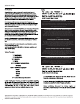
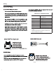
COLOR OPTIX™ WIRING OPTIONS
LED OUTPUT COLOR CONNECT THIS COLOR WIRE
TO GROUND
RED RED
GREEN GREEN
BLUE BLUE
YELLOW RED & GREEN
PINK RED & BLUE
AQUA GREEN & BLUE
WHITE RED, GREEN & BLUE
Connect colored wires on right to make output color
on le.
Connect all Yellow wires together to switched 12
Volts. See Wiring Precautions.
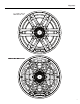
illus.-4.2
Included
Wiring
COLOR
OPT/XT"'
Wiring
COLOR
OPTIXT"'
Wiring Precautions
Do
not
connect
to
24 Volt electrical systems
We
recommend
only
using the
COLOR
OPTIX"'
wiring
chart
or
connecting to the
PMX-RGB.
Connecting
any
other
way
could cause damage
to
the speakers
or
the device
you
have
connected
to
.
We
recommend
installing
a fuse
(not
included) on the
Yellow 12 Volt wire whenever
you
are
NOT
using the
PMX-
RGB
.
See
COLOR
OPTIX"'
wiring
chart
for
wiring
options.
Rockford recommends a
minimum
of
20 gauge wire when
hard
wiring
your
COLOR
OPTIX"' speakers.
Never wire the
COLOR
OPTIX"' lights
directly
to 12 volts.
Utilize
either
the
PMX-RGB
or
a toggle switch (
not
included)
connected
to
a fused 12
volt
power
supply
. Refer to the
specifications
to
determine the size
of
fuse
(not
included)
needed
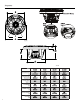
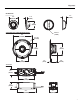
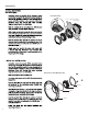
COLOR
OPTIX™
Pin
Out (wire
side)
1 -
RED
(Ground
Input)
2 - Yellow (12V +
Input)
3 - Blue (Ground
Input)
4 - Green (Ground
Input)
Included with speakers
Connector
is
DEUTSCH
™/Amphenol style
DT06-4S
i/lus.-4.1
SPEAKER
Wiring
There are
(2)
different options for wiring
your
speakers.
Use
the included spade connectors (included) as seen in illustra-
tion
3.1
You
can also utilize the
DEUTSCH™/Ampaenol
connector (not
included)
input
next to the
COLOR
OPTJX™
connector.
If
not
using the
PMX-RGB,
follow the diagrams below for proper
pin
out
and
hardwiring instructions.
COLOR
OPT/X™
Connector
-
11---,::;__
11-~-Ja:;:::::p
1 2
00
Speaker Pin
Out
(wire side)
1-
RED- Positive Speaker
Input
2 - BLACK - Negative Speaker
Input
NOT
included with speakers
Connector
is
DEUTSCH™
style
DT06-2S
i/lus.-4.3