RS2-G3 ONE BUTTON 2-WAY REMOTE START SYSTEM INSTALLATION INSTRUCTIONS CONGRATULATIONS on your choice of a “Cool Start” System with Data Port Technology for direct connection to bypass module by Crime stopper Security Products Inc. This booklet contains the information necessary for installing your remote starter system. If any questions arise, contact your installation dealer or Crime stopper Security Products Inc. at the Tech Support number below.
TABLE OF CONTENTS Pre-Installation Considerations….………...……...……………………………………………………………..….………..3 Installation Cautions & Warnings………………………………………………………………………………..….....……..3 Low Current Wiring……..…………………………………………………………………………………………….……...3-8 Parking Lights…………………………………………………………………………………………………………………...6 Power Door Lock Wiring...…………………………………….…………….……..…………...….……………….……..9-.10 Smart Tachless and Tach Finder Mode………………………………….…………………..…..…….….........................11 Tach Programming……..…..…….
INSTALLATION CAUTIONS & WARNINGS DO NOT extend the Remote start ignition harness length. Mount the module so that main harness reaches all ignition switch wiring. Extending these wires could result in poor or improper performance. DO NOT route any wiring that may become entangled with brake, gas pedals, steering column or any other moving parts in the vehicle. DO NOT exceed the rated output current of any circuit on the Remote start module.
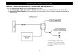
WIRING Low Current 14 Pin Plug YELLOW/BLACK OUTPUT: Ground Out when Running (Relay and/or Module not included) ANTI-GRIND RELAY: (Relay not included) The Brown 22 gauge wire can be programmed for Ground When Running (see next page) TO ENGINE IGN 1 IGN 2 ACC START CUT IGNITION SWITCH BROWN - Starter Output YELLOW/BLACK 85 86 Ground When Running MAKE CERTAIN TO CONNECT "BROWN" START OUTPUT WIRE TO STARTER SIDE OF ANTI-GRIND/START DISABLE RELAY.
WIRING Low Current 14 Pin Plug BROWN: (-) Dome Light Illumination or (-) Ground When Running (Option 13) This is a programmable output that can be programmed 2 ways: 1. 30 Second dome light with unlock = Default. The dome light turns off with ignition on or remote lock. 2. Ground Out When Running. Can be used for Anti-Grind relay or Key Sense wire sometimes required for OEM Disarm.
WIRING Low Current 14 Pin Plug WHITE: PARKING LIGHT OUTPUT RED/BLACK: INPUT SOURCE (12 Volts or Ground) The Parking Light circuit can be connected up as a high current positive or negative trigger. Connect to vehicle parking light circuit at the back of light switch or if this is not possible, connect directly to one of the parking lights at the front of the vehicle. If your vehicle has a multiplex lighting system, that will require a resistor connected in series with the white wire to the light switch.
WIRING Low Current 14 Pin Plug GRAY: (-) NEGATIVE HOOD PIN SWITCH Connect the gray wire to a switch that is at ground when the hood is open. If an existing switch is not available, then we recommend one to be installed. When this wire is grounded, the remote start is inhibited. The unit will not attempt to start if hood is open. PINK: (-) BRAKE RESET (Selectable Option 23) This is a programmable output that has 4 choices; 1. Brake Reset = Default: This is used for vehicles that have (-) brake pedal switch.
WIRING Low Current 14 Pin Plug ORANGE / BLACK: (-) OEM DISARM OUTPUT This wire provides a Ground pulse to disarm the vehicles' Factory anti-theft system prior to a Remote Start. Connect this wire to the vehicles' anti-theft disarm wire. This wire is sometimes found coming off the Driver's door key switch or at the Factory Anti-theft control module. This wire may not be needed when using a Bypass Module or if Factory Security only requires a door unlock pulse.
POWER DOOR LOCK WIRING CONNECTOR BLUE: (-) Negative pulse for UNLOCK RED: 12V When using external relays (TERM 86) GREEN: (-) Negative pulse for LOCK Crimestopper Door Lock Accessories: CS-6600DLM: Dual-relay plug-in module for Reverse Polarity, Positive, or Aftermarket Motors. CS-6500DLI: Plug-in pulse inverter that converts the Negative outputs of the system to Positive type for Positive Door Lock systems. CS-610S1: Aftermarket door lock actuator (motor).
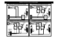
BASIC DOOR LOCK DIAGRAMS NEGATIVE TRIGGER DOORLOCK WIRING POSITIVE TRIGGER DOORLOCK WIRING GREEN GREEN RED RED BLUE BLUE FUSED +12V + 85 86 87 87A 30 FACTORY POWER LOCKING RELAYS L UL BLUE 85 86 87 87A 30 85 L UL FACTORY POWER LOCKING RELAYS AFTERMARKET MOTOR/DOOR LOCK WIRING GREEN FUSED +12V + RED BLUE 85 86 86 87 87A 30 87 87A 30 MASTER SWITCH + 87 87A 30 UL FUSED +12V + RED 86 L REVERSE POLARITY DOOR LOCK WIRING GREEN 85 CUT CUT 10 85 86 87 87A 30
“SMART TACHLESS” MODE Your CoolStart system includes a unique voltage monitor called “Smart Tachless” mode. This mode allows this unit to efficiently start an engine without the use of a tach signal wire. These modules actively monitor the voltage level of the vehicle to control the starter motor each time a remote start is requested.
TACH PROGRAMMING & TACH SIGNALS INTRODUCTION This system has 3 methods of monitoring the engine running. Option #1 controls how the system monitors the engine running. 1. Tachless Low Level Mode - Default. When vehicle is remote started, the battery voltage rate will go up because the Alternator starts working. 2. Tach Reference Mode – Monitors Engine R.P.M. - Most reliable method, see Tach programming below. 3.
DIESEL GLOW PLUG DELAY There are 2 methods of setting up a Glop Plug delay for Diesel vehicles. 1. Connecting the Pink wire directly to the wait to start lamp on vehicle. Option 23-3 must be selected for Pink wire = Glow Plug. Also, Option 20-4 must be selected for 20 seconds maximum wait time (default = 4 sec.). With this option selected, the starter will crank when the Wait-to-Start light turns off. 2. Option 20 – Pre-Set Diesel Glow Plug Delay, The choices are 4, 10, 15 and 20 seconds.
OPTION PROGRAMMING To Engage Option Programming: 1. Turn Ignition On (must be off at least 5 seconds before turning on). 2. Within 8 seconds, press valet switch 5 times. Wait for the unit to flash the parking lights and/or horn honks 5 times to confirm entering Option Mode. 3. Push the Valet program button the number of times that corresponds to the option number desired (1-24X). You must get a light flash and/or horn honk after each button press.
7 Remote Start Run Time 20 minutes 8 Lock after Remote Start (to rearm OEM alarm system) Lock after Remote Start only OFF OFF ON 10 11 Unlock before remote start (to disarm OEM alarm) Blue/orange wire selection Orange/white wire selection START ACC 12 Orange wire selection OEM Arm 13 Brown wire selection Dome Light IGN IGN Pulse after Remote Start Abort Ground when Running 10 Minutes 9 14 15 16 17 18 19 20 21 22 23 24 25 10 minutes 30 minutes Lock after Remote Start & Lock/Arm OEM Alar
OPTION DESCRIPTIONS 1. Engine Monitoring: This option controls how the system monitors the engine running. You can program for Tachless mode that monitors battery voltage, Tach mode in which the unit uses a Tach signal (RPM) or for Timed Crank as an alternative. There are 4 choices for this option: 1. Tachless (low level) – Default. When vehicle is remote started, the battery voltage rate will go up because the Alternator starts working. 2. Engine R.P.M. (Tach) - Most reliable method.
OPTION DESCRIPTIONS 4. PINK / WHITE WIRE SELECTION: This option controls the Pink / White wire function. 1. Pink / White = Ignition – Default. 2. Pink / White = Accessory 3. Pink / White = Start 5. DATA PORT PROTOCOL: Default = FORTIN This option controls the Data Port Protocol for ADS / FORTIN Series modules or D2D Series modules. The default is set for ADS IDATALINK Series Protocol. This option has no effect on conventional wiring of Bypass modules. Both Data Protocols are 2-Way communication. 6.
OPTION DESCRIPTIONS 10. BLUE/ORANGE WIRE SELECTION: This option controls the Blue/orange wire function. 1. Blue/orange = Start – Default 2. Blue/orange = Ignition 3. Blue/orange = Accessory 11. ORANGE/WHITE WIRE SELECTION: This option controls the Orange/white wire function. 1. Orange/white = Accessory – Default 2. Orange/white = Ignition. 3. Orange/white = Start 12. ORANGE WIRE SELECTION: There are 3 choices for this option. 1. Orange = OEM Arm – Default 2.
OPTION DESCRIPTIONS 15. HORN CHIRP Confirmation with LOCK or UNLOCK This option allows the system to chirp the vehicle horn for Lock and Unlock confirmation. The horn output must be connected to use this feature. Default = OFF. Lock = 1 Chirp Unlock = 2 Chirps 16. HORN CHIRPS with REMOTE START ACTIVATION: This option allows the unit to provide 3 short chirps for audible confirmation of a remote start. The horn output wire must be connected for this feature. Default = OFF. 17.
OPTION DESCRIPTIONS 21. TURBO TIMER: The optional Turbo Timer mode allows the Cool Start system to keep a Turbo or Turbo Diesel vehicle running for 1, 3 or 5 minutes [selectively] after you remove the key and exit the vehicle. This is handy for turbo cool-down without the need for expensive turbo timers. The Default = OFF. 22.TIMED SELF START MODE: Default = OFF This option allows the system to Self Start every 2, 3 or 4 hours. 23. PINK WIRE SELECTION: This is a programmable output that has 4 choices; 1.
CONNECTOR PLUG DIAGRAM ANTENNA MODULE: For optimum range and performance, the antenna should be located high up on the front windshield glass. For example: behind the rearview mirror. Note: Window tints or Films may decrease the range of the system. The mounting surface for the antenna should be clean and dry.
WIRING DIAGRAM 22
HIGH CURRENT 6-PIN HIGH-CURRENT CONNECTOR (2) RED: 12V POWER INPUT WIRES (30A Fused): Connect to both of these leads to 12V Constant Power. We recommend the BATTERY POSITIVE TERMINAL. BROWN: 12V STARTER OUTPUT 30A: Connect to circuit in the vehicle that has power ONLY while the STARTER MOTOR is CRANKING. GRAY: 12V MULTIFUNCTION OUTPUT 20A (Option 6): This is an optional multi-function output wire the can be configured as a Second IGN, ACC or STARTER output. Use Option #6 to select ACC, IGN or STARTER.
DATA PORT This unit includes DP Technology that will allow you to directly Plug-In our Data Port. There are 3 types of Protocol, ADS iDatalink series, Fortin series and d2d series modules. The default is set for Fortin series Protocol. Please refer to Databus module manual for detail instructions. The Data Port Protocol must be programmed for the correct module.
PC PROGRAMMING MENU 25
SPECIFICATIONS ELECTRICAL DC Supply voltage DC Tolerance voltage Current (With RF) Current (Without RF) 12V 9V~16V <25mA <10mA RF PARAMETERS–RX01FM Frequency Work current 433MHz <20mA T34AM-1 WAY PARAMETERS Battery voltage 2*3V Battery life Static current 6 months <3uA Work current <15mA T34FM-2 WAY PARAMETERS Battery voltage Battery life Static current transmit current Receive current 1*3V 6 months <3uA <78mA <25mA 26
changes or modifications not expressly approved by the party responsible for compliance could void the user’s authority to operate the equipment. This equipment has been tested and found to comply with the limits for a Class B digital device, pursuant to Part 15 of the FCC Rules. These limits are designed to provide reasonable protection against harmful interference in a residential installation.
www.crimestopper.