
Specifications


2
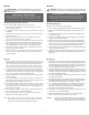
Before beginning any installation, follow these simple rules:
1. Be sure to carefully read and understand the instructions before attempting to
install these speakers.
2. For safety, disconnect the negative lead from the battery prior to beginning the
installation.
3. For easier assembly, we suggest you run all wires prior to mounting your speakers
in place.
4. Use high quality connectors for a reliable installation and to minimize signal or
power loss.
5.
Think before you drill! Be careful not to cut or drill into gas tanks, fuel lines,
brake or hydraulic lines, vacuum lines or electrical wiring when working on any
vehicle. If installation in a boat, take care not to cut or drill through the main hull.
6. Never run wires underneath the vehicle. Running the wires inside the vehicle or
hull area provides the best protection.
7. Avoid running wires over or through sharp edges. Use rubber or plastic
grommets to protect any wires routed through metal, especially the firewall.
1.
Determine wher
e the speak
ers will be mounted. Ensure an area large enough for
the speaker to mount evenly. Be sure that the mounting location is deep enough
f
or the speak
er to fit;
if mounting in a door
,
operate all functions (windo
ws,
locks,
etc.) through their entire operating range to ensure there is no obstruction.
2. Refer to the specification chart to determine the proper diameter hole to cut
f
or y
our speak
er model.
Cutting and mounting templates can be f
ound at
www.rockfordfosgate.com.
3. Mark the locations for the mounting screws. Drill the holes with a 1/8" bit.
4.
F
eed the speak
er wir
es thr
ough the cutout and connect to the speaker terminals.
Be sure to observe proper polarity when connecting the wires.The speaker's
positive terminal is indicated with a "+".
5a.
On models with slotted holes,
fit the speaker into the cutout and install the
screws in the slots at the top and bottom.This will allow you to rotate the speak-
er to match the remaining mounting holes.When aligned, tighten the screws.
5b. On models with a trim ring, fit the trim ring over the speaker and mount into
place using four (4) screws.
6.
Tighten the scr
e
ws until the speak
er is sn
ug in place to pr
event rattling. Do not
over tighten the screws.
NOTE: For T142, T1462, T152, T1S652, T1652 and T1572 only, if needed use
the adapter plate pr
ovided to mount the speaker. See Adapter Plate
T
emplates at the end of this manual.
SAFETY
CARTON CONTENTS
CAUTION: Before installation, disconnect the battery
negative (-) terminal to prevent damage
to the unit, fire and/or possible injury.
• (1) Set T1 Series Full Range Speakers
• (1) Set of grilles (T152,T1S652,T1652,T1692 and T1693 Only)
• (1) Pair of 4”x6”/6”x8” adapter plates (T142,T1462, and T1572 Only)
• (1) Pair of 5”x7”/6”x9”adapter plates (T152,T1S652, and T1652 Only)
• Mounting Hardware
INSTALLATION CONSIDERATIONS
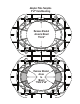
MOUNTING
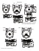
T142,
T152 and T1S652 Only
sna
p!
Removing tabs for
some in
stallations
Break off
mou
nting tab.
Use pl
iers to break off
plastic tab.
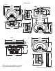
Cutout
Hole
Position to
Ali
gn Holes
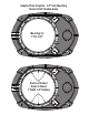
Example of standard
doo
r installation
Rear
Deck
Cutout
Hole
Example of
rear deck installation
PRACTICE SAFE SOUND™
Continuous exposure to sound pressure levels over 100dB may
cause permanent hearing loss. High powered auto sound systems
ma
y produce sound pressure levels well over 130dB. Use common
sense and practice safe sound.