
Manual

ATTENTION: To prevent electrical shock, disconnect from power source before installing or servicing.
42052-089
G. Ushakow
N/A
N/A
N/A
42052
10064901
INSTRUCTION SHEET
BULLETIN 1102C 400A/600A VACUUM CONTACTOR
CONTROL-PAK
2-20-04
Mark Jutz 2-20-04
D. Josef 2-20-04
12
42052-104
REVISION
AUTHORIZATION
DIMENSIONS APPLY BEFORE
SURFACE TREATMENT
H
A
B
C
D
E
F
G
(DIMENSIONS IN INCHES)
TOLERANCES UNLESS
OTHERWISE SPECIFIED
REFERENCE
SHEET OF
DWG.
B
DR.
CHKD.
APPD.
DATE
DATE
DATE
±
±
±
ANGLES:
.XXX:
.XX:
THIS DRAWING IS THE PROPERTY OF
THE ALLEN-BRADLEY CO. INC.
AND MAY NOT BE COPIED, USED OR
DISCLOSED FOR ANY PURPOSE EXCEPT
AS AUTHORIZED IN WRITING BY
THE ALLEN-BRADLEY CO. INC.
LOCATION : MILWAUKEE, WISCONSIN U.S.A.
SIZE
12345678
E - DOC
Bulletin 1102C 400A / 600A Vacuum Contactor
Control-Pak Installation
(Cat 1102C-CP46A, -CP46B, -CP46D, -CP46N)
Control-Pak Replacement
Cover
Coil Leads
Control-Pak
Control-Pak
Control-Pak
Remove
Coil Wire
Leads from
Control-Pak
Remove
Coil Wire
Leads from
Control-Pak
VACUUM CONT
ACTO
R
VACUUM CONTACTOR
1. Disconnect all power cables (or bus work) and all control wiring to the contactor.
2. Remove the contactor from its mounted location. The contactor is best serviced in the tabletop position.
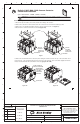
3. Remove the cover attachment hardware from the contactor and remove the cover (Figure 1).
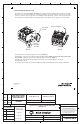
4. Disconnect the coil wire leads from the Control-Pak (Figure 2B).
5. Remove the Control-Pak from the contactor by first rotating the retainer to release the top of the Control-Pak. Then
pull out the top of the Control-Pak (the tab must clear the notch) and then push Control-Pak slightly downward to
release lower tab that holds the Control-Pak to the housing (Figures 2A & 2B).
This tab must
clear notch prior
to pushing
Control-Pak
downward.
Rotate retainer to
release Control-Pak
Figure 2A Figure 2B
400A
Figure 1
600A