
Owner's Manual Audio Recorder AR-200

8
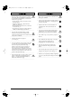
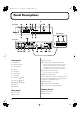
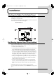
Panel Descriptions
fig.kakubu
Front panel
1.
PHONES jack
2.
MIDI/CLIP indicator
3.
SLAVE Indicator
4.
Display
5.
PLAY button
6.
PLAY indicator
7.
STOP button
8.
Decrement ( ) button
9.
Increment ( ) button
10.
MEMORY FULL indicator
11.
CARD slot
12.
Eject button
Rear panel
13.
OUTPUT jacks
14.
INPUT jacks
15.
INPUT VOLUME
16.
Control input and DC input terminal (CONT A)
* The terminal/connector section features a protective cover.
Whenever you remove this cover, such as when making
connections to the connectors, make sure not to lose it.
Additionally, keep the cover out of the reach of children.
17.
Control I/O connector (CONT B)
* This is not an RS-232C type connector.
18.
MIDI OUT/THRU connector
This is normally used as a MIDI OUT connector. However,
by using a card with settings made on an AR-3000, this can
also function as a MIDI THRU connector.
19.
MIDI IN connector
20.
AR-LINK Connectors (OUT and IN)
21.
Power connector (for supplied AC adaptor)
Bottom chassis
22.
REC MODE switches
23.
MODE switches
Front Panel
Rear Panel
Bottom Chassis
AR-200_e.book 8 ページ 2003年7月14日 月曜日 午後1時11分