To resize thickness, move all items on the front cover to left or right Version 2.0 USER GUIDE Copyright • When exchanging audio signals through a digital connection with an external instrument, this unit can perform recording without being subject to the restrictions of the Serial Copy Management System (SCMS).
To resize thickness, move all items on the front cover to left or right Information When you need repair service, call your nearest Roland Service Center or authorized Roland distributor in your country as shown below.
Contents Contents Contents ..................................................................................................3 Preparations ............................................................................................5 Required Preparations ............................................................................................................................... 5 Installing an Internal Hard Disk ............................................................................................
Contents Using Effects .........................................................................................50 Selecting the effect patch you wish to use ............................................................................................ 50 Selecting the effect bus assignment ....................................................................................................... 52 Applying a Loop Type Effect During Playback.......................................................................
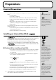
Preparations Required Preparations Preparations The VS-2480/2480CD is an audio recorder that allows multi-track recording to a hard disk. To make a multi-track recording, you will need at least the following items.
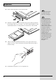
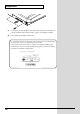
Preparations 2. Remove the front panel cover from the VS-2480. fig.01-02_50 The hard disk inside the VS-2480CD cannot be removed or exchanged. 3. With the warning label of the hard disk facing upward, slide it gently into the installation bay as far as it will go. You can hook the indentation of the attachment hardware over the protrusion on the chassis of the VS-2480. fig.01-03_40 4. After you install the hard disk to the unit you use, please lock it to fix. Apply a coin, etc.
Preparations fig.01-05_50 As described in “Turning On the Power (p. 19),” turn on the power and verify that the VS-2480 starts up correctly. If the Display Indicates “Not Found any Drives” The internal hard disk was not recognized correctly. Use the rear panel power switch to turn off the power (p. 23), and re-install the hard disk correctly. fig.dialog-NotFoundDrive 7 Preparations 6.
Preparations Installation de dispositifs optionnels (French language for Canadian Safety Standard) ■ Précautions à prendre lors de l’installation de dispositifs optionnels • Toujours éteindre et débrancher l’appareil avant de commencer l’installation de la carte. (modèle no série HDP35; User Guide p. 23). • N’installez que les cartes de disque dur spécifiées (modèle no série HDP35). Enlevez seulement les vis indiquées.
Preparations 2. Enlever les vis indiquées sur le schéma suivant et détacher la plaque avant du VS-2480. 3. Orienter le disque dur de façon à ce que la face sur laquelle est collée l’étiquette de mise en garde se trouve sur le dessus. 4. Afin d’éviter d’infliger des dommages à l’appareil lors de déplacements, enlever le disque dur installé en suivant, dans le sens contraire, les étapes de son installation de la p. 6. Il est impératif d’enlever le disque dur du VS-2480 lors de déménagement ou d’envoi.
Preparations 5. Pour ce faire, insérez une pièce de monnaie dans la fente et tournez dans le sens des aiguilles d'une montre jusqu'à ce que vous entendiez un déclic. 6. Cela signifie que le disque est bien fixé. Les vis peuvent s’enlever avec les doigts. Si elles sont trop serrées pour être dévissées avec les doigts, vous pouvez utiliser une pièce de monnaie. Si le message “Not Found any Drives” s’affiche, cela signifie que le disque dur installé n’est pas reconnu correctement.
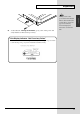
Preparations Installing Effect Expansion Boards Preparations The VS-2480/2480CD contains one VS8F-2 effect expansion board (EFFECT A section). An additional three VS8F-2 boards can be installed in the VS-2480/2480CD. When four VS8F-2 boards are installed, you will be able to use up to eight stereo effects simultaneously.
Preparations fig.01-08_50 EFFECT B EFFECT D When turning the unit upside-down, get a bunch of newspapers or magazines, and place them under the four corners or at both ends to prevent damage to the buttons and controls. Also, you should try to orient the unit so no buttons or controls get damaged. EFFECT C EFFECT A 12 3. Inside, there are four connectors and 12 resin pins.
Preparations fig.01-09(FXAssign) Preparations If the Display Indicates “No EFFECT Board” The internal effect expansion board was not detected correctly. Turn off the power (Shutdown operation), as described in “Turning Off the Power (p. 23),” and re-install the effect expansion board correctly.
Preparations Installation de la carte d’extension d’effets (French language for Canadian Safety Standard) Quand une ou deux cartes VS8F-2 sont installées, il est possible d’utiliser jusqu’à 2 effets stéréo pour chaque carte sans brancher aucun équipement additionnel au VS-2480/2480CD. Deux de ces cartes peuvent être installées dans le VS-2480/2480CD. Il est recommandé d’installer au moins une carte d’extension à effet pour pouvoir utiliser pleinement le VS-2480/2480CD.
Preparations 2. Preparations A l’intérieur se trouvent deux connecteurs et 12 goupilles de plastique. Reliez les connecteurs de la VS8F-2 à ceux du VS-2480/2480CD tout en insérant les goupilles de plastique dans les orifices de la VS8F-2. fig.1-05.f Si vous installez une seule carte d’extension d’effets, installez-la dans EFFECT A. EFFECT B EFFECT D EFFECT C EFFECT A 3. Reposez le couvercle en remettant les vis enlevées (comme spécifié) à l’étape 2.
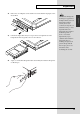
Preparations How to Replace the Battery A lithium battery inside the unit powers its time-keeping functions, and provides the power for maintaining information about certain parameters. Once this battery gets weak, the unit may no longer be able to reliably perform the time management functions for data, or return to the state is was in before power was turned off. If you see a message warning that the battery is depleted, promptly change the battery, following the procedure below. fig.01-10(BattLow) 1.
Preparations fig.battery1_69 Preparations 4. The battery should now be visible, as shown in the following. fig.battery2_69 CR2032 5. If Effect Expansion Board (VS8F-2) installed on the EFFECT A section, remove the VS8F-2 of the EFFECT A section. 6. Replace the old battery with a new one. When turning the unit upside-down, get a bunch of newspapers or magazines, and place them under the four corners or at both ends to prevent damage to the buttons and controls.
Preparations fig.battery3_69 A CR2032 lithium battery is used for the VS-2480/2480CD. This type of battery is available at an electric appliance, or similar store. 7. Reinstall the effect expansion board (VS8F-2) if removed in Step 5. Insert the plastic pin in the VS8F-2’s hole, making sure the board is securely fastened in place. 8. Use the screws that you removed in step 2 to fasten the cover back in place. This completes the process of exchanging the lithium battery. 9.
Preparations To prevent malfunction and/or damage to speakers or other devices, always turn down the volume before making any connections. The VS-2480/2480CD Support the “Mouse” and the “VGA Monitor” The VS-2480/2480CD has a “Mouse connector” that allows a mouse to be connected. If a mouse is connected, you will be able to use a mouse to operate the buttons and control knobs that appear in the display of the VS-2480/2480CD.
Preparations ■ Adjusting the Display Contrast CONTRAST fig.01-14_50 The text or icons in the VS-2480/2480CD’s display (Operation Display) may be difficult to read immediately after the unit is turned on or after it has been used for long periods, or depending on the environment in which the unit is used. If this occurs, rotate the CONTRAST knob located at the left side of the display to adjust the display contrast.
Preparations fig.01-17_50 5 3 2 F2 F3 PATCH BAY AUTOMIX F5 DISPLAY F6 HOME TRACK EDIT EZ ROUTING F4 Preparations F1 PAGE COPY MOVE TRIM IN TRIM OUT DELETE SPLIT NEW PHRASE COPY MOVE INSERT CUT ERASE COMP / EXP. IMPORT GRADATION REGION AUTOMIX A.
Preparations Setting the Date and Time of the Internal Clock The VS-2480/2480CD contains a clock. When you record a performance, a time stamp is added which indicates the date and time of the recording. This is a convenience that helps you keep track of the date or order in which recordings were made. After turning on the power for the first time after purchase, please use the following procedure to set the date and time of the internal clock. fig.
Preparations Turning Off the Power Preparations If you simply turn off the power, not only can recorded content be lost, but the VS-2480/2480CD itself could malfunction. In order to safeguard the recorded performance and turn off the power safely, you must perform the Shutdown procedure when you are finished. fig.
Preparations fig.dialog-poweroff 6. Lower the volume of your audio equipment. 7. Turn off the power of your audio equipment. 8. Use the rear panel POWER switch to turn off the VS-2480/2480CD. If “STORE Current?” is Displayed When you execute various operations (including Shutdown), “STORE Current?” (Store the current project?) may be displayed. This message asks whether or not you wish to store the currently selected project to disk.
Listening to the Demo Performance A demo performance needs to be Recovered from CD-ROM of a belonging. Also, the CD-R/RW drive such as the Roland CD Recorder is necessary to the Recover. For details please see the leaflet “To Recover the demo performance” of a belonging. A number of demo performances were placed on the hard disk inside the VS-2480CD before it left the factory. How To Load a Demo Song (CD-R Recover) 1. Turn off the power supply of all apparatus. 2. -1.
Listening to the Demo Performance projects. 11. Select the recovery-destination. Press [F4 (SelDrv)]. Use the TIME/VALUE dial to move the cursor to the recovery-destination, and press [F5 (SELECT)]. If you change your mind about the drive selection, press [F6 (CANCEL)]. 12. Press [F5 (OK)]. “Recover from SCSIx Sure?” (x is SCSI ID number) message is displayed. 13. Press [ENTER/YES]. Loading of data starts. If loading finishes, it will return to a home condition screen.
Listening to the Demo Performance For Making the Preparations Which Listen to a Demo Performance (Project Select) Select a demo song, when you listen to a demo performance. Use the following procedure to select a project. fig.2-05 TRACK EDIT EZ 1. ROUTING PATCH BAY AUTOMIX 2. Use the TIME/VALUE dial to move the cursor to the project that you want to listen to the demo project. COPY MOVE TRIM IN DELETE COPY MOVE INSERT CUT ERASE A.
Listening to the Demo Performance / Playing Back the Demo Performance / / / fig.02-01_30 FROM TRACK STATUS // PHRASE PAD SOLO MUTE TR 1-16 TR 17-24 MASTER EDIT V.
Listening to the Demo Performance 3. Press [F6 (To Pre)] to select pre level display, and press [F6 (To Pst)] once again to select post level display, alternately (except from the INPUT display or OUTPUT display). Listening to the Demo Performance The upper part of the level meter will indicate whether the current display is the pre level or the post level.
Listening to the Demo Performance Listening to the Demo Performance with a Different Arrangement (Scene) Demo performance contain several completely different sets of settings for pan, playback track, and effects etc. These settings are collectively called a scene. By recalling different scenes or changing the scene while you playback a demo performance, you can hear the demo performance arranged in different ways. Here’s how you can listen to various arrangements of the demo. fig.
Making a Multi-Track Recording This chapter explains the basic procedure for recording on the VS-2480/2480CD. Please follow through these steps to understand the procedure. Creating a New Project (Project New) Regarding Hard Disk Partition Size fig.03-01_50 3 2 F1 PAGE DISPLAY F2 F3 F4 F5 F6 HOME TRACK EDIT EZ ROUTING PATCH BAY AUTOMIX COPY MOVE TRIM IN TRIM OUT DELETE SPLIT NEW PHRASE REGION AUTOMIX UNDO COPY MOVE INSERT CUT ERASE COMP / EXP. IMPORT GRADATION A.
Making a Multi-Track Recording fig.03-01_50 6. 7. 8. 9. Use TIME/VALUE dial to select the Sample Rate (96kHz, 88.2kHz, 64kHz, 48kHz, 44.1kHz, 32kHz). Normally, choose “44.1k.” Press [ Mode.” ] to move the cursor to “Record F3 9 F4 DISPLAY F5 F6 HOME TRACK EDIT TRIM OUT DELETE SPLIT NEW PHRASE CUT ERASE COMP / EXP. IMPORT GRADATION REGION AUTOMIX FROM TO LOOP WAVE DISP UNDO REDO Use TIME/VALUE dial to select the Recording Mode (M24, MTP, CDR, M16, MT1, MT2, LIV, LV2).
Making a Multi-Track Recording Connecting Microphones Here we will explain how to connect two microphones and make a multi-track recording. One mic will record an acoustic guitar, and the other mic will record the vocal. fig.03-02_35 1. Lower the master fader of the VS-2480/2480CD to the minimum position. AUX SEND GAIN PRM EDIT FREQ EQ High IN 1-16 2. Connect the microphones to the INPUT jacks.
Making a Multi-Track Recording ■ Cautions When Connecting Microphones The pin wiring configuration of XLR type connectors is as shown below (the VS-2480/2480CD side). Please verify the pin wiring configuration before you connect any device. fig.03-05 • Depending on the location of a microphone relative to your speakers, acoustic feedback (a whining or shrieking sound) may occur. If this occurs, take the following steps. 1. Point the microphone in a different direction 2.
Making a Multi-Track Recording Adjusting the Input Sensitivity fig.03-06_50 2 1 3 DISPLAY F1 PAGE F2 F3 F4 F5 F6 HOME 1. Press [HOME (DISPLAY)]. Home Condition screen will appear. 2. Press [PAGE] several times until “INPUT” will be appeared at the [F1]. 3. Press [F1 (INPUT)]. At this time, the level meters will show the volume level of the input source. fig.
Making a Multi-Track Recording Recording On a Track This section explains the procedure for using a mic connected to the ANALOG INPUT 1 jack to record an acoustic guitar performance to track 1. fig.03-06_50 F1 PAGE 1. F2 7 F3 10 1,10 DISPLAY F4 F5 F6 HOME Press [HOME (DISPLAY)]. Home Condition screen will appear. fig.
Making a Multi-Track Recording fig.QuickRouting Press [F4 (AllClr)]. 8. Press [IN 1-16 (SOLO)]. [IN 1-16 (SOLO)] indicator will light, and channel fader will adjust the Input Mixer channel 1–16. 9. Specify the recorded on which source. Press [SELECT] of the source channel that you wish to record. For this example, Press Input Mixer Channel 1 [SELECT]. 10. If routing operation is finished, press [F6 (EXIT)] or [HOME (DISPLAY)].
Making a Multi-Track Recording Playing Back the Performance You Recorded Now let’s playback the performance that was recorded on track 1. fig.
Making a Multi-Track Recording Canceling the Recording ■ Canceling a Record Result (Undo) If the recording level was too low, if you made a mistake in your performance, or if for any other reason you wish to re-do the recording, you can use the following procedure to cancel the contents of the recording. This is called the Undo function. Undo the previously performed editing operation and return to the prior state. fig.03-16_50 1. Press [UNDO (REDO)]. 2. “UNDO Level” will appear.
Making a Multi-Track Recording ■ Re-Recording a Specified Portion (Punch-In/Punch-Out) When you listen to a performance that you recorded, you may notice that even though the overall performance is good, a mistake was made or the wrong lyrics were sung in just one location. In such cases you can use the following procedure to re-record just the portion in which the mistake occurred. This is called Punch-in/Punch-out. fig.03-18 1. 2. Press [TR 1-16 (MASTER EDIT)].
Making a Multi-Track Recording 9. Use the channel faders and master fader to adjust the volume to a comfortable level. ■ Erasing Just a Portion of a Recording (Track Erase) If instead of re-recording the portion where a mistake was made, you simply wish to erase the mistake, use the following procedure. The result will sound the same as recording silence over the unwanted section, without using additional disk space. fig.
Making a Multi-Track Recording Recording On a V.Track The VS-2480/2480CD has 24 tracks, and each of these tracks has 16 supplementary tracks called V.Tracks. By using these V.Tracks you can record up to 384 (24 x 16) tracks of audio. The following example shows how to record a performance on V.Track 2 of track 1. fig.03-22 1. IN 1-16 Press [TR 1-16 (MASTER EDIT)]. [TR 1-16 (MASTER EDIT)] indicator will light, [CH EDIT] will be the Track Mixer channel edit buttons for channels 1– 16. 2.
Making a Multi-Track Recording Comparing the Recorded content of Two V.Tracks If you have been following the procedures in the previous examples, V.Tracks 1 and 2 of track 1 contain recorded performances. Here’s how you can compare the performances of the two V.Tracks. fig.03-25 1. IN 1-16 Press [TR 1-16 (MASTER EDIT)]. [TR 1-16 (MASTER EDIT)] indicator will light, [CH EDIT] will be the Channel Edit button of the Track Mixer channel 1–16.
Making a Multi-Track Recording Recording On Other Tracks (Overdubbing) The VS-2480/2480CD allows you to record new performances on other tracks while you listen to the playback of previously recorded tracks. This process is called Overdubbing. In the following example we will explain how to use a mic connected to the INPUT 2 jack to record a vocal on track 3 while you listen to the acoustic guitar performance that you recorded earlier on track 1. As described in “Adjusting the Input Sensitivity (p.
Making a Multi-Track Recording fig.03-28_50 8. 9. 10,11 Press [REC]. [REC] indicator will blink red. Press [PLAY]. [PLAY] indicator will light green, recording will begin. ZERO STOP PLAY REC STORE SHUT / EJECT RESTART AUTOMIX REC 9 8 10. When you finish recording, press [STOP]. 11. Press [TRACK STATUS] several times until [TRACK STATUS] indicator will light green, or hold [STOP] and press [TRACK STATUS]. fig.
Making a Multi-Track Recording ■ Adjusting the Stereo Position of Each Track If you wish to adjust the stereo position (pan) of each track, use the following procedure. fig.03-34 1. 2. IN 1-16 Press [TR 1-16 (MASTER EDIT)]. [TR 1-16 (MASTER EDIT)] indicator will light, [TRACK STATUS] will display the status of the Track Mixer channel 1–16. Hold [STOP] and press [TRACK STATUS] of the track that you with to adjust the pan.
Making a Multi-Track Recording fig.03-34 2. 3. IN 1-16 Press [TR 1-16 (MASTER EDIT)]. [TR 1-16 (MASTER EDIT)] indicator will light, [CH EDIT] will be the Channel Edit button of the Track Mixer channel 1–16. Press [CH EDIT] of the track that you wish to adjust the equalizer. [CH EDIT] indicator will light. IN 17-24 AUX MST SOLO MUTE TR 1-16 TR 17-24 MASTER EDIT V.FADER FX RTN If you set the Track Mixer 17–24, press [TR 17-24/FX RTN (V.FADER)]. FADER fig.
Making a Multi-Track Recording fig.03-44_35 PAN / AUX SEND 1-8 PHRASE AUX SEND RATIO THRESHOLD ATTACK RELEASE LEVEL FREQ Dynamics 3 GAIN Filter PHRASE SEQ / AUTOMIX FREQ GAIN FREQ EQ Low Q GAIN FREQ EQ Lo - Mid Q GAIN PRM EDIT FREQ EQ High EQ Hi - Mid PAD PLAY CH EDIT / SELECT / PHRASE SEQ STATUS / AUTOMIX STATUS PHRASE SEQ IN 1-16 MANUAL IN 17-24 AUX MST WRITE READ FROM TRACK STATUS / PHRASE PAD SOLO MUTE TR 1-16 TR 17-24 MASTER EDIT V.
Making a Multi-Track Recording Saving Your Performance (Project Store) The performance that you recorded will be lost if you simply turn off the power. It will also be lost if the power should be turned off by accident or power failure. Data that was lost in this way cannot be recovered. To avoid such accidents, use the following procedure to save your project to disk.
Using Effects If VS8F-2 effect expansion boards are installed, you can use up to eight stereo effects without needing to connect any external devices to the VS-2480/2480CD. Here’s how to use effects when VS8F-2s have been installed. The VS-2480/2480CD comes equipped with one internal effects expansion board (containing two effects processors). Selecting the effect patch you wish to use The VS8F-2 contains numerous effects.
Using Effects fig.04-01_50 3. Press [PAGE] several times until function tab “Page1” will display at the front. 4-6 3 Press [F1 (FX 1)]. The effect algorithm used by effect 1 (FX 1) will be displayed. F2 F3 AUTOMIX F4 F5 DISPLAY F6 HOME 10 TRACK EDIT EZ ROUTING PATCH BAY 4. 8 8,9 F1 PAGE COPY MOVE TRIM IN TRIM OUT DELETE SPLIT NEW PHRASE COPY MOVE INSERT CUT ERASE COMP / EXP. IMPORT GRADATION REGION AUTOMIX A.
Using Effects Selecting the effect bus assignment When using the effect in a loop configuration, the AUX bus is used as the effect bus. Here we will explain how to assign the effect bus. fig.04-02_55 1. 2 Press [EZ ROUTING (PATCH BAY)]. Routing View screen will appear. F1 PAGE F2 F3 F4 Press [F4 (EFFECT)]. Loop Effect Assign screen will appear. ROUTING COPY MOVE TRIM IN TRIM OUT PATCH BAY COPY MOVE INSERT CUT A.
Using Effects Applying a Loop Type Effect During Playback It is common to apply a send/return type effect such as reverb or delay during playback. The following example shows how you can apply reverb (FX1) to track 1 during playback. fig.04-03_55 1 DISPLAY F1 PAGE F2 F3 F4 F5 F6 HOME 1. Press [HOME (DISPLAY)]. Home Condition screen will appear. 2. As described in “Selecting the effect bus assignment (p. 52),” specify which AUX bus will be used as the effect bus. 3.
Using Effects fig.04-04_30 PAN / AUX SEND 1-8 AUX SEND RATIO THRESHOLD ATTACK RELEASE LEVEL Dynamics GAIN Filter PHRASE SEQ / AUTOMIX 5 FREQ FREQ GAIN EQ Low FREQ Q GAIN EQ Lo - Mid FREQ Q GAIN PRM EDIT FREQ EQ High EQ Hi - Mid CH EDIT / SELECT / PHRASE SEQ STATUS / AUTOMIX STATUS IN 1-16 MANUAL WRITE PHRASE PAD PLAY 3 PHRASE SEQ IN 17-24 AUX MST READ FROM TRACK STATUS / PHRASE PAD SOLO MUTE TR 1-16 TR 17-24 MASTER EDIT V.
Using Effects Applying a Loop Type Effect Only to the Monitor Sound as You Record The following example shows how a source connected to the INPUT 1 jack can be recorded on track 2 directly (without effects) while you apply a send/return type effect such as reverb or delay to the monitor sound. This is convenient when you wish to hear a reverb (FX1) on a vocal (for example) as you record, but would like to try out various reverb settings during playback. fig.04-06_55 DISPLAY F1 PAGE 1.
Using Effects 7. As described in “Selecting the effect bus assignment (p. 52),” specify which AUX bus will be used as the effect bus. Here we will send the AUX1 signal to the Effect 1 (FX 1). fig.
Using Effects Switching Effects During Playback While playing back the project for track 2 that you recorded in “Applying a Loop Type Effect Only to the Monitor Sound as You Record (p. 55),” try switching the effect and listen to the result. fig.04-06_55 DISPLAY 1. F1 PAGE Press [HOME (DISPLAY)]. Home Condition will appear. F2 F3 F4 F5 F6 HOME 1 fig.
Using Effects 8. Press [TR 17-24/FX RTN (V.FADER)]. [TR 17-24/FX RTN (V.FADER)] indicator will light, channel fader will adjust the Track Mixer channel 17–24 and the Effect 1–8 Return level. 9. Raise and lower the FX1RTN fader. The effect depth will change. Adjust to the desired depth. 10. If you wish to hear other effects, repeat steps 4–9. 11. When the project playback ends, press [STOP].
Using Effects Applying a Loop Type Effect While You Record Here we will give an example of how a loop type effect such as reverb can be applied to the source of the INPUT 1 jack, and the direct sound and effect sound recorded together on track 3. This is the method you will use when, for example, you wish to apply reverb to a vocal and record both the direct sound and effect sound together. fig.04-13_60 DISPLAY PAGE F1 F2 F3 F4 F5 F6 HOME 1. Press [HOME (DISPLAY)].
Using Effects 7. As described in “Recording On a Track (p. 36)” step 6–9, specify which you wish to assign as the source. For this example, effect return (FX RET) 1 and Input Mixer channel 2 are assigned to the recording track 3. 8. As described in “Selecting the effect bus assignment (p. 52),” specify which AUX bus will be used as the effect bus. Here we will send the AUX1 signal to the Effect 1 (FX 1). 9. Press [IN 1-16 (SOLO)].
Using Effects Applying an Insertion-Type Effect During Playback When playing back an acoustic guitar or vocal, it is common to insert an effect such as “Guitar Multi” or “Vocal Multi.” Here we will give an example of applying an insertion-type effect such as Mic Modeling (FX2) to track 2 during playback. fig.04-17_60 DISPLAY F1 PAGE F2 F3 F4 F5 F6 HOME 1. Press [HOME (DISPLAY)]. Home Condition screen will appear. 2. Press [TR 1-16 (MASTER EDIT)].
Using Effects fig.04-17_60 5. Press [PAGE] several times until function tab “Page2” will be appeared at the front. 10 5 6 DISPLAY F1 PAGE F2 F3 PATCH BAY AUTOMIX F5 F6 HOME TRACK EDIT EZ ROUTING F4 COPY MOVE TRIM IN TRIM OUT DELETE SPLIT NEW PHRASE COPY MOVE INSERT CUT ERASE COMP / EXP. IMPORT GRADATION REGION AUTOMIX A.
Using Effects ■ Inserting the Same Effect into Another Track as Well If in step 8 you selected “Ins” or “InsS,” that effect cannot be inserted into another channel/track. If you choose “InsL” or “InsR,” you can use the other effect on It is not possible to use the same effect for both insertion and loop. another channel or track with Insert. fig.
Using Effects Applying an Insertion-Type Effect During Recording When recording electric guitar or vocals etc., it is common to insert an effect such as Guitar Multi or Vocal Multi. Here we will describe how you can connect an electric guitar to the GUITAR Hi-Z jack, apply an effect (FX2), and record it on track 1. fig.
Using Effects f 7 6 DISPLAY F1 PAGE F2 F3 F4 F5 F6 HOME 11 TRACK EDIT EZ ROUTING COPY MOVE TRIM IN TRIM OUT DELETE SPLIT NEW PHRASE COPY MOVE INSERT CUT ERASE COMP / EXP. IMPORT GRADATION REGION AUTOMIX A.
Using Effects fig.04-25_30 TRACK STATUS / PHRASE PAD TR 1-16 TR 17-24 MASTER EDIT V.FADER TO 13 FX RTN TRACK REC PLAY OFF 1 PHRASE PAD 17 2 18 3 19 4 20 5 21 6 22 7 23 8 9 10 11 12 13 14 15 16 24 AUX1MST AUX 2 AUX 3 AUX 4 AUX 5 AUX 6 AUX 7 AUX 8 FX1RTN FX 2 FX 3 FX 4 FX 5 FX 6 FX 7 FX 8 (dB) R FADER MASTER (dB) 6 6 4 R 4 0 0 4 4 8 8 12 12 18 18 24 24 42 42 L L 16 12 12.
Add Finishing Touches to Your Project Here we will explain the procedure by which a recorded performance can be mixed down on the VS-2480/2480CD to a two-track stereo master, and then recorded as an original audio CD. Combining the Performances of Multiple Tracks (Track Bouncing) In order to create an original audio CD, you will need the Roland CD recorder (sold separately). Performances that are recorded on two or more tracks can be mixed, and re-recorded on one or two other vacant tracks.
Add Finishing Touches to Your Project fig.05-02_30 5 PAN / AUX SEND 1-8 AUX PHRASE SEND RATIO THRESHOLD ATTACK RELEASE LEVEL Dynamics FREQ GAIN Filter PHRASE SEQ / AUTOMIX FREQ GAIN EQ Low FREQ Q GAIN EQ Lo - Mid FREQ Q GAIN EQ High EQ Hi - Mid CH EDIT / SELECT / PHRASE SEQ STATUS / AUTOMIX STATUS PHRASE SEQ IN 1-16 MANUAL 6 PAD PLAY PRM EDIT FREQ IN 17-24 AUX MST WRITE READ FROM TRACK STATUS / PHRASE PAD SOLO MUTE TR 1-16 TR 17-24 MASTER EDIT V.
Add Finishing Touches to Your Project recorded on tracks 7 and 8 just as you hear it. It is best to record at as high a level as possible without allowing the sound to distort. 13. Press [IN 17-24/FX RTN (MUTE)]. [IN 17-24/FX RTN (MUTE)] indicator will light, faders become the adjusting levels for Input Mixer channel 17–24 and effect 1–8. 14. Raise and lower FX1RTN fader, to adjust the effect return level.
Add Finishing Touches to Your Project 22. Hold [REC] and press channel 7 or 8 [TRACK STATUS]. fig.05-01_50 25,31,36 29,33 ZERO STOP PLAY REC STORE SHUT / EJECT RESTART AUTOMIX REC 22,30 28,35 23. Press [TR 1-16 (MASTER EDIT)]. [TR 1-16 (MASTER EDIT)] indicator will light, channel faders become the Track Mixer level for channel 1–16. 24. Lower the channel fader 7 or 8 to the lowest position. fig.
Add Finishing Touches to Your Project Signal Flow (Routing) fig.05-04 9 AUX1MST FX1RTN FX Send FX1 7 1 MASTER 23 17 (dB) 6 R 4 (dB) R 0 6 4 0 4 TR1 8 12 18 24 42 L PAN 4 + TR7 8 12 18 24 + 42 L MASTER OUT, MONITOR OUT 30. Press [REC]. [REC] indicator will blink red. 31. Press [PLAY]. [PLAY] indicator will light green, and recording will begin. 32. When you finish recording, press [STOP]. The project playback will stop. 33. Press [ZERO].
Add Finishing Touches to Your Project Mixing down to the mastering tracks (Mastering Room) Here’s how to select the mastering tracks (any V.Track of the track 23/24), and perform a mixdown.In order to create an original audio CD, you can specify two of the VS-2480/2480CD’s tracks as the left track and right track, and write them to a CD-R disc. A performance that has not yet been mixed down must be mixed down to 2-track stereo. When 96k, 88.2k or 64kHz is selected, that Mastering Tool Kit cannot be used.
Add Finishing Touches to Your Project 5. Use TIME/VALUE dial to select “On.” A dedicated mastering track will appear. 6. Use [ ][ ][ ][ ] to move the cursor to “STATUS.” 7. Use TIME/VALUE dial to select “Rec.” Allowing you to mix down to the mastering track. fig.05-09_50 8. Use [ ][ TRACK FROM EFFECT UTILITY TO LOOP WAVE DISP UNDO REDO Mastering track. For this example, select “1.” ][ PROJECT OUT MENU Use TIME/VALUE dial to select the V.Track of 10.
Add Finishing Touches to Your Project fig.05-10_35 IN 1-16 16. Press [TR 1-16 (MASTER EDIT)]. [TR 1-16 (MASTER EDIT)] indicator will light, and channel faders will adjust the Track Mixer channel 1–16. 17. Hold [STOP], press [TRACK STATUS] for the Track Mixer channel 1–24 which you want to mixdown. [TRACK STATUS] indicator will light green. IN 17-24 AUX MST SOLO MUTE TR 1-16 TR 17-24 MASTER EDIT V.FADER To switch the [TRACK STATUS] of tracks 17–24, press [TR 17-24 / FX RTN (V.
Add Finishing Touches to Your Project Signal Flow (Routing) fig.05-11a Track 1--24 MIX L R 1 17 (dB) R (dB) 6 6 4 R MST TR L 4 0 0 4 TR1 Mastering Track MASTER 4 PAN 8 12 18 8 12 18 24 24 42 42 MST TR R L MASTER OUT MONITOR OUT L MASTER 23. Use the TIME/VALUE dial or the SHUTTLE ring to move to the time location (such as 00h00m00s00f) at which you wish to begin mixdown. 24. Press [REC]. The [REC] indicator will light in red. 25. Press [PLAY].
Add Finishing Touches to Your Project 3. Use [ 4. Use TIME/VALUE dial to select ][ ][ ][ ] to move the cursor to switch. For details on the signal flow at this time, refer to “Signal Flow (Routing) (p. 76).” “On.” A dedicated mastering track will appear. 5. Use [ ][ ][ ][ ] to move the cursor to “STATUS.” 6. Use TIME/VALUE dial to select “Play.” A dedicated mastering track will appear, allowing you to playback to the mastering track. 7.
Add Finishing Touches to Your Project Erasing an Unwanted Portion (Track Cut) Project data that was track-bounced will be recorded to the CD-R disc starting form “00h00m00s00” of that track and ending at the end of the project (project end). This means that if there are silent portions at the beginning or end of the performance, that capacity of the CD-R disc will be wasted. To avoid this, you can erase unwanted portions. fig.
Add Finishing Touches to Your Project 6. 7. Use the TIME/VALUE dial or SHUTTLE ring to move to the time location at which you wish to stop writing. Press [2]. The end time of the project will be registered, and the [2] indicator will light. ■ Deleting an Unwanted Portion At the End of the Project fig.05-07_50 1. 2. Press [HOME (DISPLAY)]. Home Condition will appear. Press [PHRASE/REGION] in TRACK EDIT several times until indicator light red.
Add Finishing Touches to Your Project ■ Deleting an Unwanted Portion At the beginning of the Project fig.05-08_50 1. 2. Press [HOME (DISPLAY)]. Home Condition will appear. Press [PHRASE/REGION] in TRACK EDIT several times until indicator light red. 9 DISPLAY F1 PAGE 6 F3 ROUTING AUTOMIX F4 F5 F6 HOME 1,11 TRACK EDIT EZ PATCH BAY 4 F2 COPY MOVE TRIM IN TRIM OUT DELETE SPLIT NEW PHRASE COPY MOVE INSERT CUT ERASE COMP / EXP. IMPORT GRADATION REGION AUTOMIX A.
Add Finishing Touches to Your Project Adding Track Number Markers By placing two or more projects one after the other in the same track, you can write these projects consecutively to the CD-R disc. In this case, you can place markers between projects to function as track numbers, just as on a pre-recorded audio CD. These track numbers will be written to the audio CD that you record on your CD-R drive. REDO fig.05-14_55 1.
Add Finishing Touches to Your Project ■ Assigning Track Numbers When you write an audio CD, a track number will automatically be assigned to “00h00m00s00f.” For this reason, the track number markers and the actual project order will be as follows. fig.
Creating an Original Audio CD This chapter explains how you can create an original audio CD by recording two tracks (stereo tracks) from the VS-2480/2480CD to the CD recorder. CD-RW (Appendices P. 12) SCSI (Appendices P. 12) Connecting the CD-R/RW Drive A CD-R/RW drive allows you to use CD-R or CD-RW discs to create audio CDs. CD-R discs are the preferred format for audio CDs. 1. Make sure that the power of all devices is turned off. 2. Use a SCSI cable to connect the Roland CD recorder. 3.
Creating an Original Audio CD fig.06-01_50 4 F1 PAGE DISPLAY F2 F3 F4 F5 F6 HOME TRACK EDIT EZ ROUTING COPY PATCH BAY AUTOMIX MOVE TRIM IN TRIM OUT DELETE SPLIT NEW PHRASE REGION AUTOMIX UNDO COPY MOVE INSERT CUT ERASE COMP / EXP. IMPORT GRADATION A.
Creating an Original Audio CD Finalize “Finalize” means to write the TOC (Table Of Contents) to the audio CD created by the VS-2480/2480CD. If a CD-R disc has not been finalized, additional songs can be written to the unused area of that disc. However, such a disc cannot be played back on a conventional CD player. The CD player function of the VS-2480/2480CD allows you to audition a disc even before (or after) it has been finalized.
Creating an Original Audio CD Writing speed to CD-R (For example) MAX: Write to the disc with the maximum speed. x4: The project will be written at quad speed. x2: The project will be written at double times speed. When writing speed is early many time is not required. However, in many instances where a disc could not be written to successfully, it is due to the fact that the speed was just too fast for processing to take place reliably.
Creating an Original Audio CD Auditioning the Project You Wrote To check (audition) the project you wrote to the disc, use the following procedure. 1. Insert the CD-R disc into the CD-R/RW drive. Finalize (Appendices P. 12) fig.06-06_50 2. Press [HOME (DISPLAY)]. Home Condition screen will appear. F1 PAGE 4 F2 DISPLAY F3 F4 F5 F6 HOME 2 TRACK EDIT EZ ROUTING COPY MOVE TRIM IN TRIM OUT DELETE SPLIT NEW PHRASE COPY MOVE INSERT CUT ERASE COMP / EXP.
About the Demo Performances About the Demo Performances 87
: About the Demo Performances 88
Index A After Rec ......................................................................... 73 B Loop Type Effect ............................................... 53, 55, 59 Low Pass Filter ............................................................... 48 LPF ................................................................................... 48 48 48 18 16 48 48 M CD player ....................................................................... 86 CD-R Write screen .....................................
Index T Tone ................................................................................. Track Cut ............................................................................. Erase .......................................................................... Track Bouncing .............................................................. Track Number ................................................................ 46 77 41 67 80 U UNDO Level .............................................................
To resize thickness, move all items on the front cover to left or right Information When you need repair service, call your nearest Roland Service Center or authorized Roland distributor in your country as shown below.
To resize thickness, move all items on the front cover to left or right Version 2.0 USER GUIDE Copyright • When exchanging audio signals through a digital connection with an external instrument, this unit can perform recording without being subject to the restrictions of the Serial Copy Management System (SCMS).