V-Card: Owner’s Manual 03897845 ’05-3-1N To resize thickness, move all items on the front cover and registration marks to left or right. Owner’s Manual The V-Synth XT comes with the VC-1 and VC-2 titles from Roland's “V-Card” software series preinstalled. Without having to cycle power to the unit, you can simply press a single switch to transform the V-Synth XT into a completely different product. Copyright © 2005 ROLAND CORPORATION All rights reserved.
To resize thickness, move all items on the front cover and registration marks to left or right.
vc1_for_XT_e1 3 ページ 2005年3月8日 火曜日 午後12時55分
vc1_for_XT_e1 4 ページ 2005年3月8日 火曜日 午後12時55分 Table of Contents Introduction................................................................................................6 Panel Descriptions ....................................................................................8 Try Out the Sounds .................................................................................11 Turning On the Power .............................................................................................................
vc1_for_XT_e1 5 ページ 2005年3月8日 火曜日 午後12時55分 Table of Contents Key Mode Alteration ..........................................................................................76 Sound List ..........................................................................................................78 Preset Patches.......................................................................................................................................................... 78 Patch Factors ............................
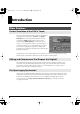
vc1_for_XT_e1 6 ページ 2005年3月8日 火曜日 午後12時55分 Introduction Main Features Perfect Simulation of the D-50’s Tones! fig.01-01 The VC-1 comes complete with all 64 of the D-50’s preset patches, including the famous preset tones “Fantasia” and “Digital Native Dance.” It also is programmed with the D-50/D-550 sound libraries PN-D50-01–04 (with 256 patches). Since it naturally handles MIDI bulk dumps, you can use the VC-1 to create your own original tunes exactly as you would with your D-50.
vc1_for_XT_e1 7 ページ 2005年3月8日 火曜日 午後12時55分 Introduction What is the digital synthesizer: D-50? The D-50, released in 1987, was Roland’s first fully digital synthesizer. Equipped with an LA (Linear Arithmetic Synthesis) format sound generator that combined PCM and subtractive synthesis, it opened the door to countless new sounds for levels of creativity surpassing anything up to that point.
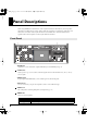
vc1_for_XT_e1 8 ページ 2005年3月8日 火曜日 午後12時55分 Panel Descriptions When using the VC-1, the actual functions of the V-Synth XT’s buttons and knobs may not correspond to the functions ascribed to these controls on the V-Synth XT’s panel. Here is a description of the names and functions in each section of the V-Synth XT when it is used with the VC-1. Please read this material together with “Panel Descriptions” in the V-Synth XT Owner’s Manual. Front Panel fig.
vc1_for_XT_e1 9 ページ 2005年3月8日 火曜日 午後12時55分 Panel Descriptions 7 8 9 10 LCD CONTRAST Knob Adjusts the display contrast. Display This displays information regarding the operation you are performing. * The explanations in this manual include illustrations that depict what should typically be shown by the display. Note, however, that your unit may incorporate a newer, enhanced version of the system (e.g.
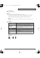
vc1_for_XT_e1 10 ページ 2005年3月8日 火曜日 午後12時55分 Panel Descriptions Rear Panel 12 14 15 12 AC Inlet Connect the included power cord to this inlet. 13 DIGITAL AUDIO INTERFACE Connector These connectors input/output a digital audio signal (stereo; conforming to IEC60958). The output signal is identical to the signal that is output from the MAIN OUT jacks. * 14 15 10 13 IEC60958 is a digital interface format used for consumer digital audio devices.
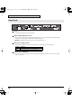
vc1_for_XT_e1 11 ページ 2005年3月8日 火曜日 午後12時55分 Try Out the Sounds Turning On the Power To prevent malfunction and/or damage to speakers or other devices, always turn down the volume, and turn off the power on all devices before making any connections. fig.03-01e(ConnectionImage) 1. Before hooking anything up, make sure that the power on all of your gear is turned OFF. 2. Connect the V-Synth XT to your amp/speaker system. 3. Turn on the V-Synth XT’s Power switch. 4.
vc1_for_XT_e1 12 ページ 2005年3月8日 火曜日 午後12時55分 Try Out the Sounds Selecting Patches and Playing Sounds The VC-1 comes with a wide range of onboard sounds, including single tones called patches. A Patch is represented by a Patch Bank (Pre1–6, Int1–8), a Bank (1–8) and a Number (1–8). fig.03-03e(PatchBankImage) Patch bank (Pre1–6) Patch bank (Int1–8) Int7Int8 Int5Int6 Int3Int4 Int2 Int1 Pre6 Pre5 Pre4 Pre3 Pre2 Pre1 Number 1 2 3 4 5 6 7 8 Bank Bank 1 2 3 4 5 6 7 8 Number 1 2 3 4 5 6 7 8 Patch No.
vc1_for_XT_e1 13 ページ 2005年3月8日 火曜日 午後12時55分 Try Out the Sounds Selecting Patches with the VALUE dial fig.03-04e(PatchNumber) 1. Make sure the PATCH TOP screen is displayed. If the PATCH TOP screen—shown right—is not displayed, press [EXIT] once or twice until the PATCH TOP screen appears. 2. Play the keyboard to hear what the selected patch sounds like. To change to a different patch, touch the Patch number to highlight it, and then turn the VALUE dial or press [INC/+], [DEC/-].
vc1_for_XT_e1 14 ページ 2005年3月8日 火曜日 午後12時55分 Try Out the Sounds Viewing Various Information 1. 2. In the upper right of the screen, touch < >. A pulldown menu appears. In the pulldown menu, touch . The Information window appears. fig.08-13 3. This window shows the following information. Ver.: The VC-1’s program version 4. When you have finished viewing the information, press [EXIT] to close the window.
vc1_for_XT_e1 15 ページ 2005年3月8日 火曜日 午後12時55分 Applying Effects to the Sound The performance controlling functions (we call them factors in this manual) in each Patch can be edited by taking the following procedure. A patch consists of several Factors as show below. fig.05-01e(PatchFactorImage) Tone Tune UPPER Tone Key Mode Variations of Control Functions Tone Balance Output Mode (Reverb, etc.
vc1_for_XT_e1 16 ページ 2005年3月8日 火曜日 午後12時55分 Applying Effects to the Sound Assigning Parameters to the Controllers You can assign a variety of patch factors (p. 81), tone parameters (p. 82), and other settings to the V-Synth XT’s complement of controller sections. This is referred to as the Control Setup. With intuitive editing of sound sources with the knobs, you can use the D-50 in ways that go way beyond the original instrument. Parameters Patch Factor (p. 81) Tone Parameters (p.
vc1_for_XT_e1 17 ページ 2005年3月8日 火曜日 午後12時55分 Applying Effects to the Sound LIST (OSC1, OSC2, COSM1, COSM2 and TVA) • Tone Parameters; The Tones (UPPER or LOWER) to be applied are specified with the Tone Select button. • Partial Parameters; The Partials (L1, L2, L3 or L4) to be applied are specified with the Partial Select button. fig.
vc1_for_XT_e1 18 ページ 2005年3月8日 火曜日 午後12時55分 Applying Effects to the Sound table You can control the following parameters. Display Parameters PATCH TOP (p. 19) ToneBal Tone Balance PATCH EDIT CONTRL (p. 21) BendRang Bender Range Aftertouch Bend AftrPB Range PortTime Portamento Time PortMode Portamento Mode PATCH EDIT OUTPUT (p. 22) Rev Bal Reverb Balance TotalVol Total Volume PATCH EDIT CHASE (p. 24) ChasLevl Chase Level ChasTime Chase Time PATCH EDIT TONE TUNE (p.
vc1_for_XT_e1 19 ページ 2005年3月8日 火曜日 午後12時55分 Applying Effects to the Sound How to Make the Patch Factors The Display shows several Factors at a time. If necessary, Scroll up or down the Display to find the Factor to be edited. (Patch Parameters; p. 19) fig.05-12(LCD_PatchEditControl) 1. Access the PATCH TOP Screen. 2. Touch at the bottom of the screen. 3. Touch one of the tabs in the left of the screen to select the desired editing screen. : Control Edit, Portamento Edit (p.
vc1_for_XT_e1 20 ページ 2005年3月8日 火曜日 午後12時55分 Applying Effects to the Sound Display WHOLE DUAL SPLIT SEP (Separate) WHOL-S (Whole Solo) DUAL-S (Dual Solo) SPL-US (Split Upper Solo) SPL-LS (Split Lower Solo) SEP-S (Separate Solo) Description Upper Tone can be played in 16 voice polyphony Both Upper and Lower Tones are played by each key in 8 voices polyphony. The Split mode divides the keyboard into upper and lower sections, where two different Tones can be played in 8 voices polyphony.
vc1_for_XT_e1 21 ページ 2005年3月8日 火曜日 午後12時55分 Applying Effects to the Sound CONTROL fig.05-15(LCD_PatchEditControl/Bend) Patch Controls determine how the Control Functions actually affect the Upper and the Lower Tones. Bend (Bender Range) This sets the variable range of the pitch change caused by moving the Bender lever fight and left. The variable range set here may result differently depending on the setting of the Tone Parameter Bender Mode (p. 60).
vc1_for_XT_e1 22 ページ 2005年3月8日 火曜日 午後12時55分 Applying Effects to the Sound OUTPUT (Output Mode) The Output Mode determines how the Tones take on the reverb effect, and how the Tones appear at the outputs. A sound reverberated in an acoustic environment consists of three parts. First, you hear the direct sound as it travels from the source outward. Next the early reflection resounds once, or several time, from the walls, ceiling ,and floor.
vc1_for_XT_e1 23 ページ 2005年3月8日 火曜日 午後12時55分 Applying Effects to the Sound RevType (Reverb Type) Selects one of the 32-reverb types.
vc1_for_XT_e1 24 ページ 2005年3月8日 火曜日 午後12時55分 Applying Effects to the Sound CHASE The Chase Play function makes it possible to output the Lower Tone slightly later than the Upper Tone, which is actually played on the keyboard. This function, however, is only available in Dual or Whole Key Mode. fig.05-17(LCD_PatchEditControl/Chase) Mode (Chase Mode) Sets how tones sound. Depending on the Chase Level and Velocity, the number of repeats of the delayed sound differ.
vc1_for_XT_e1 25 ページ 2005年3月8日 火曜日 午後12時55分 Applying Effects to the Sound TONE TUNE The relative pitch of the Upper and the Lower Tones can be separately set. By setting slightly different pitches, a detune effect can be obtained. Also, by lowering the pitch of the Upper Tone, and raising the pitch of the Lower Tone, the pitches of the Two Tones can become exactly the same. fig.
vc1_for_XT_e1 26 ページ 2005年3月8日 火曜日 午後12時55分 Saving Patches You’ve Created When you edit the settings of a patch, the PATCH TOP screen displays to remind you that the patch’s settings have been modified. If is displayed, you will lose your edited patch settings if you switch to another patch or turn off the power. If you want to keep a patch whose settings you have edited, assign a name to the patch and then perform the Save operation.
vc1_for_XT_e1 27 ページ 2005年3月8日 火曜日 午後12時55分 Saving Patches You’ve Created Saving Patches Changes you make to sound settings are temporary, and will be lost if you turn off the power or select another sound. If you keep the modified sound, you must save it (PATCH WRITE). When you perform the save procedure, the data that previously occupied the save destination will be lost. However, the factory setting data can be recovered by performing the Factory Reset. (p. 28) 1.
vc1_for_XT_e1 28 ページ 2005年3月8日 火曜日 午後12時55分 Saving Patches You’ve Created Reset to Default Factory Settings This restores all data in the VC-1 to the factory-set condition (Factory Reset). If there is important data you’ve created that’s stored, all such data is discarded when a Factory Reset is performed. If you want to keep the existing data, save it as describe below. • Transmit it to an original D-50 (or an external MIDI device), and save it (p. 33).
vc1_for_XT_e1 29 ページ 2005年3月8日 火曜日 午後12時55分 Transferring Patches To and From the D-50/550 * You can use MIDI to transmit patch data (64 patches) saved on your D-50 and receive the data with the VC-1 (V-Synth XT). This procedure is known as “bulk load.” This is an easy and convenient way to take your own original patches (64 patches) created with the D-50 and use them with the VC-1. Conversely, you can also send patch data edited using the VC-1 via MIDI to the D-50. This procedure is called “bulk dump.
vc1_for_XT_e1 30 ページ 2005年3月8日 火曜日 午後12時55分 Transferring Patches To and From the D-50/550 Transfer the patch from the memory card to the D-50/550 All the 64 Patches data stored on the Memory Card can be loaded to the D-50/550’s internal memory. Using the D-50 2-1 6-1 2-2 6-2 4 [EXIT] 3 5 1. Insert the Memory Card (M-256D) into the D-50 Card Slot. 2. Turn the Memory Protect of the D-50 to OFF. 2-1. Press the [TUNE/FUNCTION] button. 2-2.
vc1_for_XT_e1 31 ページ 2005年3月8日 火曜日 午後12時55分 Transferring Patches To and From the D-50/550 Transferring Patches from the D-50/550 to the VC-1 * * You cannot bulk load data when a patch in the Preset Banks (Pre1 – Pre6) is selected. The VC-1 display does not change immediately following the bulk load. This is due to the fact that the work area is the bulk load destination (p. 37). You can confirm the outcome of the transfer by switching patches with the VALUE dial. Using the D-50 3, 4 6 5 1.
vc1_for_XT_e1 32 ページ 2005年3月8日 火曜日 午後12時55分 Transferring Patches To and From the D-50/550 Saving Transferred Patches The transferred patch data (64 patches) will be lost if you turn off the power. Be sure to save the data. fig.04-04(LCD_ModeMenu_DataTrans) 1. Press [MODE] on the VC-1. The MODE MENU window appears. 2. Touch . The DATA TRANSFER screen appears. fig.04-04a(LCD_DataTrans_BankSave) 3. Touch in the left of the screen. The Bank Copy screen appears. 4.
vc1_for_XT_e1 33 ページ 2005年3月8日 火曜日 午後12時55分 Transferring Patches To and From the D-50/550 Transferring Patches from the VC-1 to the D-50/550 Using the D-50 3-1 3-2 4-1, 4-2 12 4-3 1. Use a MIDI cable to connect the V-Synth XT’s MIDI OUT connector to the D-50’s MIDI IN connector. 2. Set the D-50 and V-Synth XT to the same MIDI channel (the basic channel; p. 73). 3. Turn the Memory Protect of the D-50 to OFF. 3-1. Press the [TUNE/FUNCTION] button. 3-2.
vc1_for_XT_e1 34 ページ 2005年3月8日 火曜日 午後12時55分 Transferring Patches To and From the D-50/550 Using the D-550 3-2 4-2 3-2 3-1 4-1 4-2 1. Use a MIDI cable to connect the VariOS’s MIDI OUT connector to the D-550’s MIDI IN connector. 2. Set the D-550 and V-Synth XT to the same MIDI channel (the basic channel; p. 73). 3. Turn the Memory Protect of the D-550 to OFF. 3-1. Press the D-550’s [TUNE] button. 3-2. 4. Select “Protect” with the [ ] or [ ] buttons, and turn it OFF with the [VALUE].
vc1_for_XT_e1 35 ページ 2005年3月8日 火曜日 午後12時55分 Transferring Patches To and From the D-50/550 10. Touch . The bulk dump starts. If you want to cancel without executing, touch . 11. When the data transfer is completed, the D-50’s display shows “Complete.” 12. Press the [EXIT] button on the D-50 to return to the play mode. Copying a Reverb Type In addition to the patches (64 patches), 16 reverb types (17–32 are also saved to the VC-1’s patch banks (Pre 1–6, Int 1–8).
vc1_for_XT_e1 36 ページ 2005年3月8日 火曜日 午後12時55分 Transferring Patches To and From the D-50/550 fig.04-07(LCD_DataTrans_ReverbCopy) 3. Touch in the left of the screen. The REVERB COPY screen appears. 4. Modify the value by either turning the VALUE dial or pressing [INC/+] or [DEC/-]. Source Bank Selects the source Patch Bank of Reverb Type. Value: P1 – P6, I1 – I8 No. Selects the source Reverb Type. Value:1 – 32 Destination Bank Selects the destination Patch Bank of Reverb Type.
vc1_for_XT_e1 37 ページ 2005年3月8日 火曜日 午後12時55分 Overview of the VC-1 Memory Structure fig.07-01(MemorySuructure) 2 Temporary Area Patch (1) Patch Write Patch:Int1 (64) Int1–Int8 (512) Wave (128) Patch Write Bank Save Patch Select Patch:Int1 (64) Int1–Int8 (512) Power ON Wave (128) 1 Bulk Load Patch (64) Bulk Dump Wave (100) Work Area 1 Work Area Once the V-Synth XT has started up the VC-1, the system program and patch data is loaded from the VC-1 into the V-Synth XT.
vc1_for_XT_e1 38 ページ 2005年3月8日 火曜日 午後12時55分 Overview of the VC-1 The Basic Concept of a Tone Throughout the process of programming the D-50, the operation remains simple and logical. You can think of the D-50 having powerful synthesizers built in. Each of these hypothetical synthesizers could behave like a convention analog synthesizer, or a PCM sampled synthesizer. Any combination of two synthesizers can achieve some remarkable cross-modulation effects. fig.
vc1_for_XT_e1 39 ページ 2005年3月8日 火曜日 午後12時55分 Overview of the VC-1 PCM sound generator A PCM sound generator provides 128 different PCM sampled sounds (= waveform). fig.07-04(BlockDiagramPCM) WG ROM DSP PCM Wave Memory Interpolator Pitch Processor 2 TVA TVA Envelope Generator Structure Structure, which is one of the Common Parameters, determines which two of the hypothetical synthesizers (a synthesizer sound generator or a PCM sound generator) are to be used as Partial 1 and Partial 2. fig.
vc1_for_XT_e1 40 ページ 2005年3月8日 火曜日 午後12時55分 Overview of the VC-1 Ring Modulator The Ring Modulator multiplies two sounds, creating an unusual and metallic sound that contains complicated harmonics. For instance, two waveforms ( multiplied and waveform and ) are is created. This is effective for making metallic sounds. fig.
vc1_for_XT_e1 41 ページ 2005年3月8日 火曜日 午後12時55分 Overview of the VC-1 Structure of Tone Parameters Depending on which generators are selected in the Partial Block, greatly different Tone Parameters will be used. Some Tone Parameters used for the Synthesizer sound generators are irrelevant to the PCM generator. In a Structure with Ring modulation, some parameters of Partial 2 are automatically set to those of Partial 1. fig.
vc1_for_XT_e1 42 ページ 2005年3月8日 火曜日 午後12時55分 Overview of the VC-1 TVF (Time Variant Filter) This fitter passes lower frequency harmonics and cuts off the higher ones. By changing the cutoff point and the resonance, the waveform changes. 4 Cutoff Frequency This sets the cutoff point. The cutoff point can be controlled by parameter). 5 TVF ENV and any LFO (= Common Resonance This emphasizes the cut off point, making more unusual or electronic sounds.
vc1_for_XT_e1 43 ページ 2005年3月8日 火曜日 午後12時55分 Creating a Patch With the VC-1, you have total control over a wide variety of settings. Each item that can be set is known as a “parameter.” When you change the values of parameters, you are doing what is referred to as “editing.” This chapter explains the procedures used in creating patches, and the functions of the patch parameters. There are two methods of sound creation. • Editing an existing sound.
vc1_for_XT_e1 44 ページ 2005年3月8日 火曜日 午後12時55分 Creating a Patch Useful Functions for Editing The VC-1 provides numerous ways in which you can edit your own patches more conveniently. Editing a Value To edit a value, you can use the VALUE dial, [INC/+] or [DEC/-].In each VC-1 screen, you can select a value using the cursor as described earlier, and modify its value. Each parameter has its own range of possible values.
vc1_for_XT_e1 45 ページ 2005年3月8日 火曜日 午後12時55分 Creating a Patch Editing with the Panel Controls (Partial Select) You can assign a variety of parameters (such as TVF Resonance or TVA Level) to the knobs at the right of the front panel for direct, intuitive editing of the parameters. The partials to which the tone parameters assigned to the different knobs are applied are specified in the PATCH TOP screen or with STRUCTURE [1] at the right of the front panel.
vc1_for_XT_e1 46 ページ 2005年3月8日 火曜日 午後12時55分 Creating a Patch Copying Tone Settings A Tone from another Patch can be copied to the patch currently selected (Tone Copy). fig.08-05(LCD_Pulldown_ToneCopy) 1. Make sure the PATCH TOP screen is displayed. 2. Touch < appears. 3. In the pulldown menu, touch . The TONE COPY window appears. > in the upper right of the screen. A pulldown menu fig.08-06(LCD_ToneCopyWindow) 4.
vc1_for_XT_e1 47 ページ 2005年3月8日 火曜日 午後12時55分 Creating a Patch Copying Parameter Settings A group of Tone parameters can be copied within a Patch (Parameter Copy). fig.08-06a(LCD_Pulldown_ParamCopy) 1. Make sure the PATCH TOP screen is displayed. 2. Touch < appears. 3. In the pulldown menu, touch . The PARAM COPY window appears. > in the upper right of the screen. A pulldown menu fig.08-06b(LCD_ParamParamWindow) 4.
vc1_for_XT_e1 48 ページ 2005年3月8日 火曜日 午後12時55分 Creating a Patch PARTIAL (Source Partial) If PART-1 or PART-2 is selected in Value: PART-1, PART-2 * 6. When , select the corresponding block. is set to All or COMMON, setting is ignored. Touch to execute the copy operation. If you want to cancel without executing, touch . Auditioning the Sound Before Editing While editing a parameter, you may wish to hear the original sound before it was edited.
vc1_for_XT_e1 49 ページ 2005年3月8日 火曜日 午後12時55分 Creating a Patch Initializing Patch Settings Initialize means to return the settings of the currently selected patch to a standard set of values. The Initialize operation will affect only the currently selected patch in temporary area; the patches that are stored in internal memory and work area will not be affected. If you wish to restore all of the VC-1’s settings to their factory values, perform a Factory Reset (p. 28). fig.08-09(Patch_Initialize) 1.
vc1_for_XT_e1 50 ページ 2005年3月8日 火曜日 午後12時55分 Tone Parameters Common Parameters fig.09-01(LCD_Structure) : : : : (p. 50) (p. 51) (p. 53) (p. 54) Structure Struct (Structure Number) Select one of the following seven Structures. Value: 1–7 Number 1 S Partial 1 Partial 2 Combination of two Partials S S Mixture of Partial 1 and partial 2. S S Mixture of Partial 1 and ring-modulation. P S Mixture of Partial 1 and partial 2.
vc1_for_XT_e1 51 ページ 2005年3月8日 火曜日 午後12時55分 Tone Parameters P-ENV (Pitch Envelope) P-ENV Edit (Envelope) fig.09-09(LCD_P-ENV_PEnvEdit) Velo (Velocity Range) Sets the maximum effect of the velocity that controls the pitch of the P-ENV. At higher values, the keyboard velocity has a greater, effect on the envelope. Value: 0–2 fig.09-10(TimeKeyFollow) TKF (Keyfollow (Time)) Sets the time of the P-ENV depending on the key played. Higher values change the time more drastically.
vc1_for_XT_e1 52 ページ 2005年3月8日 火曜日 午後12時55分 Tone Parameters fig.09-12(LCD_P-ENV/Time) T1 (Time 1) Sets the time needed from point 0 (the moment the key is pressed) to point 1. Value: 0–50 T2 (Time 2) Sets the time needed from point 1 to point 2. Value: 0–50 T3 (Time 3) Sets the time needed from point 2 to point 3. Value: 0–50 T4 (Time 4) Sets the time needed from the moment the key is released to point 4. Value: 0–50 P-ENV Level Edit fig.
vc1_for_XT_e1 53 ページ 2005年3月8日 火曜日 午後12時55分 Tone Parameters * The maximum variable range of each level will depend on the Velocity Range in P-ENV. (p. 51) Velocity Range 0 1 2 Level +50 -50 +50 -50 +50 -50 Range +1 octave -1 octave +1.5 octave -1.5 octave +2 octave -2 octave Pitch Mod (Pitch Modulation) Depending on how the LFO in WG modulation (p. 60) is set, the vibrato set here may have no effect at all. fig.
vc1_for_XT_e1 54 ページ 2005年3月8日 火曜日 午後12時55分 Tone Parameters Delay (Delay Time) This sets the time needed for the LFO to appear, from the moment a key is pressed. Higher values increase the delay time. Value: 0–100 Sync Selects the timing of the LFO oscillation as follows. For LFO-2 and LFO-3, KEY cannot be selected. Value: OFF, ON, KEY Display OFF ON KEY Description LFO does not sync to the keyboard.
vc1_for_XT_e1 55 ページ 2005年3月8日 火曜日 午後12時55分 Tone Parameters fig.09-18e(EQ_Hf/HQ) HiFreq (High Frequency) Sets the frequency where the gain is altered in the middle to high range. Value: 250, 300, 350, 420, 500, 600, 700, 840 Hz, 1.0, 1.2,\r1.4, 1.7, 2.0, 2.4, 2.8, 3.4, 4.0, 4.8, 5.7, 6.7, 8.0, 9.5 kHz HQ is Height. HQ is low. Level 0 HiFreq HiQ (High Q) Sets the width of the frequency band where the gain is boosted or cut. With a higher value, the frequency band is narrower, and vice versa.
vc1_for_XT_e1 56 ページ 2005年3月8日 火曜日 午後12時55分 Tone Parameters Balance (Chorus Balance) This sets the volume balance of the chorus of the chorus sound and normal sound. Value: 0–100 Value 100 50 0 Balance Only the chorus sound is heard. Chorus sound = Normal sound Only the normal sound is heard. Partial Parameters Restriction of the available parameters caused by Structure Depending on what Structure (p. 50) is used, the available parameters may be different. 1.
vc1_for_XT_e1 57 ページ 2005年3月8日 火曜日 午後12時55分 Tone Parameters WG Form (WG Waveform) WG Form (Waveform) fig.09-21(LCD_PART1-FORM) Wave (Waveform) Selects the waveform of the synthesizer sound generator. Value: SQU, SAW Display Waveform SQU (square) SAW (Sawtooth) * A sawtooth waveform is produced by processing a square Waveform at the TVF, that is, all the waveform are square at WG even when a sawtooth is selected.
vc1_for_XT_e1 58 ページ 2005年3月8日 火曜日 午後12時55分 Tone Parameters fig.09-24(VelocityRange) Velo (Velocity Range) Sets the sensitivity of the velocity that controls the pulse width. With “-” values, the pulse width becomes smaller by playing the keyboard harder, and with “+” values, the pulse width becomes wider by playing the keyboard harder. Value: -7–+7 After (Aftertouch Range) Sets the sensitivity of the aftertouch that controls the pulse width.
vc1_for_XT_e1 59 ページ 2005年3月8日 火曜日 午後12時55分 Tone Parameters WG PITCH WG Pitch fig.09-26(LCD_WgPitch) Coars (Pitch Coarse) Sets the standard pitch of a Partial in semi-tone steps. The standard pitch is the pitch at C5 (middle C) key. Value: C1–C7 Fine (Pitch Fine) The standard pitch can be altered over about +/- 50 cents. Value: -50–+50 fig.09-27e(PitchKeyFollow) KF (Keyfollow (pitch)) Usually, the keyboard to a synthesizer assigns a semi-tone to each key.
vc1_for_XT_e1 60 ページ 2005年3月8日 火曜日 午後12時55分 Tone Parameters WG Mod (WG Modulation) fig.09-27z(LCD_PitchWfMod) LFO (LFO Mode) fig.09-28e(LFO_Mode) Selects one of the following four vibrato modes. Value: OFF, (+), (-), A&L Display OFF (+) (-) A&L Description No vibrato is obtained. Vibrato is on. Vibrato is on but inverted. Vibrato can be obtained only by Aftertouch and Bender Lever. Normal "-" is selected. ENV (P-ENV Mode) fig.
vc1_for_XT_e1 61 ページ 2005年3月8日 火曜日 午後12時55分 Tone Parameters Bender Mode Example: • If the Bender range is set to 12 (1 octave), and the Keyfollow (Pitch) of WG is set to 2, the maximum pitch change caused by moving the Bender Lever is 2 octaves. • When the Keyfollow (Pitch) of WG is set to zero, there is no pitch change caused by the Bender lever. TVF (Time Variant Filter) TVF fig.09-30(LCD_TVF/TVF) fig.
vc1_for_XT_e1 62 ページ 2005年3月8日 火曜日 午後12時55分 Tone Parameters fig.09-32e(Resonance) Reso (Resonance) Boosts the cutoff point. As you increase the value, specific harmonics are emphasized and the sound will become more unusual, more electronic in nature. Value: 0–30 100 Level Frequency Cutoff Point Frequency Cutoff Point Frequency Cutoff Point Frequency Level Cutoff Point Value Level Level 0 fig.
vc1_for_XT_e1 63 ページ 2005年3月8日 火曜日 午後12時55分 Tone Parameters Keyfollow Adjustment fig.09-34e(bias/direction) Angle 0 Value Middle C (C4) The curve in the picture represents the Keyfollow value with the bias level added. • TVF Keyfollow (Cutoff Point): • Bias Direction: 0 >C4 TVF ENV (TVF Envelope) fig.09-35(LCD_TVF/TVF ENV) Depth (ENV Depth) Sets the depth of the TVF ENV modulation that changes the TVF cutoff Point. Higher values deepen the effect.
vc1_for_XT_e1 64 ページ 2005年3月8日 火曜日 午後12時55分 Tone Parameters TVF ENV Time An envelope curve is determined by times and levels. fig.09-37e(TvfEnvTime) Point 1 Point 2 Point 3 Point 4 L1 T1 T2 L2 T3 L3 SusL Point 5 EndL T4 Key On T5 Key Off fig.09-38(LCD_TvfEnvTime) T1 (Time 1) Sets the time needs to reach point 1 from the moment the key is pressed. Value: 0–100 T2 (Time 2) Sets the time needed to reach point 2 from point 1.
vc1_for_XT_e1 65 ページ 2005年3月8日 火曜日 午後12時55分 Tone Parameters TVF ENV Level fig.09-39(LCD_TvfEnvLevel) L1 (Level 1) Sets the of point 1. Value: 0–100 L2 (Level 2) Sets the level of point 2. Value: 0–100 L3 (Level 3) Sets the level of point 3. Value: 0–100 SusL (Sustain Level) This sets the level of point 4. Value: 0–100 EndL (End Level) To lower the level after releasing the key, set this to 0, and to raise the level, set it to 100.
vc1_for_XT_e1 66 ページ 2005年3月8日 火曜日 午後12時55分 Tone Parameters TVA (Time Variant Amplifier) TVA fig.09-40(LCD_TvaTva) Level Sets the volume of a Partial. Higher values may cause sound distortion. If so, lower the value. Even when the Level is set to zero here, the sound may not be completely muted if the TVA ENV curve is high. Value: 0–100 Velo (Velocity Range) Sets the sensitivity of the velocity that controls the volume of the sound.
vc1_for_XT_e1 67 ページ 2005年3月8日 火曜日 午後12時55分 Tone Parameters TVA ENV (Envelope) fig.09-42(LCD_TvaEnv) Velo (Velocity Follow (Time 1)) Sets the sensitivity of the velocity than controls the Time 1 of the TVA ENV. Increasing the sensitivity shortens Time 1, by stronger playing. Value: 0–4 fig.09-36(TimeKeyFollow) TKF (Keyfollow (Time)) This can change the time o the TVA ENV depending on the key played. 0 to 4 are valid. Higher values change the time more drastically.
vc1_for_XT_e1 68 ページ 2005年3月8日 火曜日 午後12時55分 Tone Parameters T4 (Time 4 Sets the time needed to reach point 4 from point 3. Value: 0–100 T5 (Time 5) Sets the time needed to reach point 5 from the moment the key is released. Value: 0–100 TVA ENV Level fig.09-44(LCD_TvaEnvLevel) L1 (Level 1) Sets the level of point 1. Value: 0–100 L2 (Level 2) Sets the level of point 2. Value: 0–100 L3 (Level 3) Sets the level of point 3. Value: 0–100 SusL (Sustain Level) Sets the level of point 4.
vc1_for_XT_e1 69 ページ 2005年3月8日 火曜日 午後12時55分 Tone Parameters MOD (Modulation) TVF MOD fig.09-45(LCD_ModTvfMod) LFO (LFO Select) Selects the LFO that changes cutoff point periodically (creating growl effects). Value: +1, -1, +2, -2, +3, -3 fig.09-25e(LFO Select) Display +1 -1 +2 -2 +3 -3 LFO (Phase) LFO-1 (+) LFO-1 (-) LFO-2 (+) LFO-2 (-) LFO-3 (+) LFO-3 (-) Positive Phase (+) Negative Phase (-) LFOD (LFO Depth) Sets the depth of a growl effect. Higher values deepen the effect.
vc1_for_XT_e1 70 ページ 2005年3月8日 火曜日 午後12時55分 Tone Parameters TVA MOD fig.09-46(LCD_ModTvaMod) LFO (LFO Select) Selects the LFO that changes the volume periodically (tremolo effects) . Value: +1, -1, +2, -2, +3, -3 fig.09-25e(LFO Select) Display +1 -1 +2 -2 +3 -3 LFO (phase) LFO-1 (+) LFO-1 (-) LFO-2 (+) LFO-2 (-) LFO-3 (+) LFO-3 (-) Positive Phase (+) Negative Phase (-) LFOD (LFO Depth) Sets the depth of the tremolo effect. Higher values deepen the effect.
vc1_for_XT_e1 71 ページ 2005年3月8日 火曜日 午後12時55分 Settings for the Entire VC-1 Settings that affect the entire operating environment of the VC-1, such as tuning and MIDI message reception, are referred to as System functions. This section explains how to make settings for the System functions and describes the functions of the different System parameters. How to Make the System Function Settings fig.10-01(LCD_ModeMenu) 1. Press [MODE]. The MODE MENU window appears. 2. Touch .
vc1_for_XT_e1 72 ページ 2005年3月8日 火曜日 午後12時55分 Settings for the Entire VC-1 fig.10-03(LCD_SystemGeneral) Sound Setting Master Tune Adjusts the overall tuning of the VC-1. The display shows the frequency of the A4 note (center A). Value: 427 – 452 Hz Sound Character Sets whether the output characteristics of the sound are the same as those of the D-50 (D-50) or the V-Synth XT (V-Synth). Value: D-50, V-Synth Digital Freq (Digital Frequency) Sets the sampling frequency of the digital output. Value: 44.
vc1_for_XT_e1 73 ページ 2005年3月8日 火曜日 午後12時55分 Settings for the Entire VC-1 fig.10-04(LCD_SystemMidi) MIDI MIDI CH (MIDI Channel) Sets the Basic Channel (MIDI channel on which the VC-1 receives and transmits messages). Value: 1 – 16 * The transmit change can be set to a different number from the Basic Channel individually from each Patch (p. 25). Control Determines how to receive messages from an external MIDI device. (“Key Mode Alteration” (p. 76)) Value: B.CH, G.CH, MdeOFF Display B.
vc1_for_XT_e1 74 ページ 2005年3月8日 火曜日 午後12時55分 Settings for the Entire VC-1 Exclusive (Exclusive Switch) To receive or transmit Exclusive messages (Roland ID Number only), set this to On, P-Dump or TxEdit. Value: Off, On, P-Dump, TxEdit Display On P-Dump TxEDIT * Function Normally. The patch data that you select is transmitted. The parameter data that you edited is transmitted. When set to P-Dump, the Patch you select is transmitted to an external device.
vc1_for_XT_e1 75 ページ 2005年3月8日 火曜日 午後12時55分 Settings for the Entire VC-1 Initializing the System Settings The current settings of the system functions can be restored to a set of standard settings, or to the factory settings (System Initialize). fig.10-04a 1. Access the System Edit screen. 2. Touch , located in the lower right of the screen. 3. If you want the factory settings to be in effect the next time the VC-1 is powered up, touch to save the settings.
vc1_for_XT_e1 76 ページ 2005年3月8日 火曜日 午後12時55分 Key Mode Alteration Poly Mode or Mono Mode is an element that determines how to output the Upper and Lower Tones. Mono Mode, Poly Mode There are two ways of the The VC-1 can use either mode. Name Poly Mode Mono Mode * Functions Allows the control of more than one Key message on one channel at a a time. The VC-1 is 16 or 8 voices polyphonic (depending on the patch used). So the Poly Mode can be used the VC-1 is controlled by a keyboard or sequencer.
vc1_for_XT_e1 77 ページ 2005年3月8日 火曜日 午後12時55分 Key Mode Alteration Key Mode Poly Mode Mode Message Off Lower Mono Mode Upper Lower Upper Dual Receive Channel Lower Upper Dual-S (Dual Solo) Receive Channel (Group) Receive Channel Lower Upper Split Lower Upper Rceive Channel Lower Upper Split-US (Split Upper Solo) Receive Channel Lower Upper Receive Channel (Group) Split-LS (Split Lower Solo) Receive Channel Lower Upper Lower Upper Separate Receive Channel Lower Upper Receive Channel
vc1_for_XT_e1 78 ページ 2005年3月8日 火曜日 午後12時55分 Sound List Preset Patches P1 (Preset 1:Original D-50) 2 No.
vc1_for_XT_e1 79 ページ 2005年3月8日 火曜日 午後12時55分 Sound List P3 (Preset 3:PN-D50-01) 2 No.
vc1_for_XT_e1 80 ページ 2005年3月8日 火曜日 午後12時55分 Sound List P5 (Preset 5:PN-D50-03) No.
vc1_for_XT_e1 81 ページ 2005年3月8日 火曜日 午後12時55分 Sound List Patch Factors Patch Factors PATCH TOP (p. 19) Chase Switch Chase Switch Portament Switch Portamento Switch Value KEY MODE Key Mode SPLIT BALANCE CONTROL (p. 21) Bend Split Point Tone Balance OFF, ON OFF, ON WHOLE, DUAL, SPLIT, SEP, WHOL-S, DUAL-S, SPL-US, SPL-LS, SEP-S C2 – C7 0 – 100 Bender Range 0 – 12 AfterPB Hold Time Aftertouch Bend Range Hold Mode Portamento Time -12 – +12 U, L, UL 0 – 100 Mode OUTPUT (p.
vc1_for_XT_e1 82 ページ 2005年3月8日 火曜日 午後12時55分 Sound List Tone Parameters Common Parameters Value Parameter Struct (p. 50) Structure Partial Balance P-ENV (p.
vc1_for_XT_e1 83 ページ 2005年3月8日 火曜日 午後12時55分 Sound List Value Parameter Comment EQ/Chorus (p. 54) EQ Chorus LowFreq Low Frequency LowGain Low Gain HiFreq High Frequency HiQ High Q 63, 75, 88, 105, 125, 150, 175, 210, 250, 300, 350, 420, 500, 600, 700, 840 -12 – 12 250, 300, 350, 420, 500, 600, 700, 840, 1.0, 1.2, 1.4, 1.7, 2.0, 2.4, 2.8, 3.4, 4.0, 4.8, 5.7, 6.7, 8.0, 9.5 0.3, 0.5, 0.7, 1.0, 1.4, 2.0, 3.0, 4.2, 6.
vc1_for_XT_e1 84 ページ 2005年3月8日 火曜日 午後12時55分 Sound List TVF ENV TVF ENV Time TVF ENV Level Value Parameter Depth Depth 0 – 100 Velo Velocity Range 0 – 100 DKF Depth Keyfollow 0–4 TKF Time Keyfollow 0–4 T1 Time1 0 – 100 T2 Time2 0 – 100 T3 Time3 0 – 100 T4 Time4 0 – 100 T5 Time5 0 – 100 L1 Level1 0 – 100 L2 Level2 0 – 100 L3 Level3 0 – 100 SusL Sustain Level 0 – 100 EndL End Level 0, 100 Level Level 0 – 100 Velo Velocity Range BP Bias Point/Bias Direction
vc1_for_XT_e1 85 ページ 2005年3月8日 火曜日 午後12時55分 Sound List System Parameters Parameter Sound Setting (p. 72) Master Tune Sound Character Digital Freq MIDI (p. 73) MIDICH Control Separate CH Prog.C Exclusive Bank.S Value Master Tune Sound Character Digital Output Frequency 427 – 452 Hz D-50, V-Synth 44.1, 48, 96 kHz Basic CH Control Separate Mode Receive CH Program Change Switch Exclusive Switch Bank Select Switch 1 – 16 B.CH, G.
vc1_for_XT_e1 86 ページ 2005年3月8日 火曜日 午後12時55分 Sound List Waveform Oneshot Number 1 2 3 4 5 6 7 8 9 10 11 12 13 14 15 16 17 18 19 20 21 22 23 24 25 26 27 28 29 30 31 32 33 34 35 36 37 38 39 40 86 Display Marmba Vibes Xylo1 Xylo2 Log_Bs Hammer JpnDrm Kaimba Pluck Chink Agogo 3angle Bells Nails Pick Lpiano Mpiano Hpiano Harpsi Harp Orgprc Steel Nylon Eguit1 Eguit2 Dirt P_Bass Pop Thump Uprite Clarnt Breath Steam FluteH FluteL Guiro IndFlt Harmo Lips1 Lips2 PCM Name Marimba Vibraphone Xylophone 1 Xylophone
vc1_for_XT_e1 87 ページ 2005年3月8日 火曜日 午後12時55分 Sound List Loop (Some of the sounds 1 to 76, are combined and looped.
vc1_for_XT_e1 88 ページ 2005年3月8日 火曜日 午後12時55分 MIDI Implementation Model: Date: Version: VC-1 January 10, 2005 1.10 ■System Realtime Messages ●Active Sensing 1. Data Transmission Status FEH ■Channel Voice Messages * ●Control Change ●System Exclusive Messages Status ❍Bank Select (Controller number 0, 32) Status 2nd byte BnH 00H BnH 20H n = MIDI channel number: mm, ll = Bank number: * * 3rd byte mmH llH 0H - FH (ch.1 - 16) 00 00H - 7F 7FH (bank.1 - bank.
vc1_for_XT_e1 89 ページ 2005年3月8日 火曜日 午後12時55分 MIDI Implementation ❍Modulation (Controller number 1) 2. Receive data Status 2nd byte BnH 01H n = MIDI channel number: vv = Modulation depth: ■Channel Voice Messages ●Note off 2nd byte Status 8nH kkH 9nH kkH n = MIDI channel number: kk = note number: vv = note off velocity: 3rd byte vvH 00H 0H - FH (ch.1 - 16) 00H - 7FH (0 - 127) 00H - 7FH (0 - 127) 3rd byte vvH 0H - FH (ch.
vc1_for_XT_e1 90 ページ 2005年3月8日 火曜日 午後12時55分 MIDI Implementation <<< RPN >>> Control Changes include RPN (Registered Parameter Numbers), which are extended. When using RPNs, first RPN (Controller numbers 100 and 101; they can be sent in any order) should be sent in order to select the parameter, then Data Entry (Controller numbers 6 and 38) should be sent to set the value. This device receives the following RPNs.
vc1_for_XT_e1 91 ページ 2005年3月8日 火曜日 午後12時55分 MIDI Implementation 3. Exclusive Communication ■ 3.1 Message structure All exclusive communications are based on following structure ( Roland Exclusive Format Type IV ).
vc1_for_XT_e1 92 ページ 2005年3月8日 火曜日 午後12時55分 MIDI Implementation ■ 3.
vc1_for_XT_e1 93 ページ 2005年3月8日 火曜日 午後12時55分 MIDI Implementation ■ 3.
vc1_for_XT_e1 94 ページ 2005年3月8日 火曜日 午後12時55分 MIDI Implementation ■ 3.
vc1_for_XT_e1 95 ページ 2005年3月8日 火曜日 午後12時55分 MIDI Implementation * 1: table 1 (Common Parameter - Partial Mute) BIN 00B 01B 10B 11B DEC 0 1 2 3 D 7 8 9 10 11 12 13 14 15 16 17 18 19 20 21 22 23 24 25 26 27 28 29 30 31 Description Partial2 Off, Partial1 Off Partial2 Off, Partial1 On Partial2 On, Partial1 Off Partial2 On, Partial1 On * 2: table 2 (Patch Parameter - Tone Select) BIN 00B 01B 10B 11B DEC 0 1 2 3 Description Upper Off, Lower Off Upper Off, Lower On Upper On, Lower Off Upper On, Lower On
vc1_for_XT_e1 96 ページ 2005年3月8日 火曜日 午後12時55分 Date : January 10, 2005 MUSIC SOFTWARE MIDI Implementation Chart Model: VC-1 Transmitted Function...
vc1_for_XT_e1 97 ページ 2005年3月8日 火曜日 午後12時55分 Specifications VC-1: V-Card D-50 Sound Generator D-50 Compatible LA (Linear Arithmetic) Synthesis Polyphony 16 voices Waveforms Synthesizer: 2 PCM: 128 Internal (User) Memory Banks: 8 Patches: 512 Preset Memory Banks: Patches: * 6 384 In the interest of product improvement, the specifications and/or contents of this unit are subject to change without prior notice.
vc1_for_XT_e1 98 ページ 2005年3月8日 火曜日 午後12時55分 Index A AC Inlet ........................................................................................................ 10 After ............................................................................................ 53, 58, 69–70 AfterPB ......................................................................................................... 21 Aftertouch ...................................................................................................
vc1_for_XT_e1 99 ページ 2005年3月8日 火曜日 午後12時55分 Index K O KEY MODE .................................................................................................. 19 Key Shift of the Lower Tone ...................................................................... 25 Key Shift of the Upper Tone ...................................................................... 25 Keyfollow (Cutoff Point) ........................................................................... 62 Keyfollow (Depth) ...............
vc1_for_XT_e1 100 ページ 2005年3月8日 火曜日 午後12時55分 Index R Rate ......................................................................................................... 53, 55 Receive Channel in Separate Mode .......................................................... 25 Reso ............................................................................................................... 62 Resonance .................................................................................................... 62 Revbal .