MC-505cover.e 99.6.17 11:25 AM Page 1 Owner's Manual Before using this unit, carefully read the sections entitled: ÒIMPORTANT SAFETY INSTRUCTIONSÓ (Owner's Manual, p. 2), ÒUSING THE UNIT SAFELYÓ (Owner's Manual, p. 3), and ÒIMPORTANT NOTESÓ (Owner's Manual, p. 13). These sections provide important information concerning the proper operation of the unit. Additionally, in order to feel assured that you have gained a good grasp of every feature provided by your new unit, *** should be read in its entirety.
Used for instructions intended to alert the user to the risk of death or severe injury should the unit be used improperly. Used for instructions intended to alert the user to the risk of injury or material damage should the unit be used improperly. * Material damage refers to damage or other adverse effects caused with respect to the home and all its furnishings, as well to domestic animals or pets. - ¥ Before using this unit, make sure to read the instructions below, and the Owner's Manual. ..............
Contents Main Features ....................................................................9 Front and Rear Panels......................................................10 Important Notes...............................................................13 Chapter 1. an Overview of the MC-505 ............................14 How the MC-505 Is Organized ..........................14 About the Sound Generator...............................14 About the Sequencer .........................................
Making More Detailed Settings........................................49 Applying Cyclic Changes to the Sound (LFO) ......50 Selecting the Waveform That Will Modulate the Sound (LFO1 Waveform)...............................................................50 Adjusting the Speed of Modulation (LFO1 Rate) ..........51 Adjusting the Depth of Modulation (LFO1 Depth).......51 Making More Detailed Settings........................................52 Common Settings ..............................................
General Purpose Multi-Effects..........................................86 Selecting the Type (EFX Type)..........................................86 4 Band EQ (Modify the Tone) ...........................................87 Spectrum (Add Character to the Sound).........................88 Enhancer (Add Sparkle to the Sound).............................89 Overdrive (Distort the Sound Mildly).............................89 Distortion (Distort the Sound Severely) ..........................
Chapter 8. Combining Phrases to Saving the Exchanged Pattern .........................120 Create a Different Pattern (MEGAMIX) . 119 Exchanging Phrases ........................................119 Selecting a Distant Pattern...............................120 Chapter 9. Using the DBeam Controller to Apply Various Effects ..121 Using the DBeam Controller.............................121 How Each Type Will Function ...........................121 01:Modulation-A (Modulation All)................................
Chapter 11. Editing Patterns (Pattern Edit) ........................ 146 Copying a Portion of a Pattern (Copy) .............146 Erasing Unwanted Data (Erase) .......................147 Deleting Unwanted Measures (Delete Measure)...148 Inserting Blank Measures (Insert Measure) ......149 Transposing the Pitch (Transpose)....................150 Modifying the Strength of Notes (Change Velocity) ............................................150 Modifying the Note Length (Change Gate Time)...
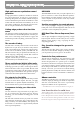
Chapter 14. Using Memory Cards ........................................ High-performance synthesizer sound generator A high-performance synthesizer module is featured for sound generation. A rich array of parameters, including sharp filters and standard ADSR envelopes can be modified from panel knobs and sliders to create sounds with the same hands-on immediacy as on vintage analog synthesizers. The MC-505 will also function as an 8-part multitimbral sound module.
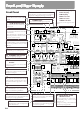
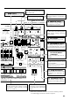
Front and Rear Panels Front Panel 1 VOLUME Knob Controls the overall volume of the MC-505. 2 3 6 You can apply a variety of effects to patterns and patches simply by moving your hand. 4 MODE Section Here you can switch the operating mode. These show various types of information. LOW BOOST Section This controls the effect of the low boost section.
9 8 WAVE SELECT Button Select the waveform that will be the basis of the sound. BANK Section 11 Select the bank of the pattern or patch. 10 PITCH Section Adjusts the pitch of the sound. FILTER/AMPLIFIER Section Adjusts the brightness and dynamics of the sound. 12 ENVELOPE Section Adjusts time-varying changes in pitch, brightness and volume.
Rear Panel 7 CAUTION ATTENTION: RISQUE DE CHOC ELECTRIQUE NE PAS OUVRIR WARNING: 6 RISK OF ELECTRIC SHOCK DO NOT OPEN TO REDUCE THE RISK OF FIRE OR ELECTRIC SHOCK, DO NOT EXPOSE THIS APPLIANCE TO RAIN OR MOISTURE. S2M-5/S4M-5 5 4 3 2 THIS CLASS B DIGITAL APPARATUS MEETS ALL REQUIREMENTS OF THE CANADIAN INTERFERENCE-CAUSING EQUIPMENT REGULATIONS. CET APPAREIL NUMÉRIQUE DE LA CLASSE B RESPECTE TOUTES LES EXIGENCES DU RÈGLEMENT SUR LE MATÉRIEL BROUILLEUR DU CANADA.
Important Notes In addition to the items listed under ÒIMPORTANT SAFETY INSTRUCTIONSÓ and ÒUSING THE UNIT SAFELYÓ on pages 2 and 3, please read and observe the following: Power Supply ¥ Do not use this unit on the same power circuit with any device that will generate line noise (such as an electric motor or variable lighting system). ¥ Before connecting this unit to other devices, turn off the power to all units. This will help prevent malfunctions and/or damage to speakers or other devices.
Chapter 1. an Overview of the MC-505 A brief explanation of the MC-505Õs internal organization was provided in the Quick Start manual, but this chapter contains a more detailed explanation of the basic sections: the controller section, sound generating section, and the sequencer section. How the MC-505 Is Organized 1 fig.1-3 Sound generator section About the Sound Generator Tones and Patches ÒTonesÓ are the smallest unit of sound used by the MC-505, and one tone produces one sound.
Chapter 1. an Overview of the MC-505 Rhythm Set Parts 1Ð7 A collection of various rhythm instruments (rhythm tones) is referred to as a Rhythm Set. A different rhythm tone can be assigned to each key (note number), allowing you to use a large number of rhythm tones at once. There are two types of rhythm sets: ÒPreset Rhythm SetsÓ which are already built into the MC-505, and ÒUser Rhythm SetsÓ which accommodate the rhythm sets that you create.
Chapter 1. an Overview of the MC-505 About the Sequencer 1 PRESET The sequencer records your performance and controller operations as musical data. Playing back the sequencer will cause this recorded musical data to be sent to the sound generator, making it produce sound. In other words, the sequencer plays the instrument instead of the musician. In the sense that it records and plays back a performance, a sequencer is similar to a tape recorder.
Chapter 1. an Overview of the MC-505 Temporary Area (Temporary pattern) Basic Operation When you play a sound or select a patch for editing, the selected patch is called into a location known as the Òtemporary area.Ó When you edit or record a pattern, the contents of the pattern are automatically copied to U:TMP (temporary pattern ), and your operations will affect this data. Modifying a Value To select a patch or pattern, or to modify a parameter value, use the VALUE dial or the INC/DEC buttons. fig.
Chapter 1. an Overview of the MC-505 Canceling the Previous Operation (Undo/Redo) 1 The function that restores an edited musical data to its previous condition is called Undo, and the function that restore the ÒundoneÓ or musical data to the edited condition is called Redo. The MC-505 lets you use undo/redo for the following operations. This is convenient when you wish to cancel a change, or to compare your edits with the original data. ¥ Pattern Edit ☞ ÒEditing Patterns (Pattern Edit )Ó (p.
Chapter 2. Playing Patterns Playing Patterns 1. Make sure that the PTN indicator is lit. If it is not lit, press [MODE] to make it light (Pattern mode). fig.2-1 SONG MODE PTN 2. Press [PTN/SONG]. The indicator will light. The display will indicate the bank, number and name of the currently selected pattern. The pattern that is currently playing back is referred to as the Òcurrent pattern,Ó and the pattern that is scheduled to play next is called the Ònext pattern.
Chapter 2. Playing Patterns ●●●●●●●●●●●●●●●●●●●●●●●●●●●●●●●●●●●●●●●●●●●●●●●●●●●●●●●●●●●●●●●●●●●●●●●●●●●●●●●●●●●●●●●●●●●●●●●●●●●● 2 Fast-forward and rewind Each time you press [FWD], the pattern will advance one measure. Each time you press [BWD], the pattern will go back one measure. If you hold down [SHIFT] and press [FWD], you will advance to the last measure. If you hold down [SHIFT] and press [BWD], you will return to the beginning.
Chapter 2. Playing Patterns tern playback, the tempo value of the previous pattern will be maintained. fig.2-13 RHYTHM MUTE ●●●●●●●●●●●●●●●●●●●●●●●●●●●●●●●●●●●●●●●●●●●●●●●●●●●●●●●●●●●●●●●●●●●●●●●●●●●●●●●●●●●●●●●●●●●●●●●●●●●● Muting Patterns During pattern playback, you can mute the playback of a specific part or rhythm tone. Muting a Part (Part Mute) 1. Press [PART MUTE]. The indicator will light, and the PART button [R]Ð [7] indicators will show the current status of that part.
Chapter 2. Playing Patterns Playing back the next pattern with the current mute settings (Mute Remain) With the next pattern selected, press [PLAY] to make the indicator blink, and the current mute status will be maintained for the next pattern. 2. The transposition will be applied from the moment that you press the keyboard pad. To return to the original key, press [TRANSPOSE] once again to make the button indicator go dark. ☞ ÒShifting the Keyboard Range in OneOctave Steps (Octave Shift)Ó (p.
Chapter 2. Playing Patterns ●●●●●●●●●●●●●●●●●●●●●●●●●●●●●●●●●●●●●●●●●●●●●●●●●●●●●●●●●●●●●●●●●●●●●●●●●●●●●●●●●●●●●●●●●●●●●●●●●●●● The part selected by the PART SELECT button and PART buttons is referred to as the Òcurrent part.
Chapter 2. Playing Patterns ●●●●●●●●●●●●●●●●●●●●●●●●●●●●●●●●●●●●●●●●●●●●●●●●●●●●●●●●●●●●●●●●●●●●●●●●●●●●●●●●●●●●●●●●●●●●●●●●●●●● Hold If you press [HOLD] to make the indicator light, the sound will continue even after you take your finger off of the keyboard pad. Press [HOLD] once again to make the indicator go dark, and the sound will stop.
Chapter 2. Playing Patterns Adjusting the Pitch of Each Part (Part Key Shift) You can adjust the pitch of the sound of each part. fig.2-29 LEVEL +48 PAN KEY SHIFT REVERB DELAY EFX/OUT MEGAMIX -48 1. Press [MIXER SELECT] several times to make the KEY SHIFT indicator light. 2. Move the part sliders [R]Ð [7] to adjust the pitch of each part. Range: -48Ð+48 semitones Raising the slider will raise the pitch. Lowering the slider will lower the pitch.
Chapter 2. Playing Patterns SHIFT 8 Saving Patterns YouÕve Modified (Pattern Write) Part INT Current Part BOTH EXT 2. Use [PART SELECT] and the PART buttons to select the part for which you wish to modify settings. The setting value for the selected part will be shown at the right of the display. 2 * ÒMÓ stands for the MUTE CTRL part, and mainly contains muting data and tempo data (p. 131, 141). 3. Use [INC] [DEC] or the [VALUE] dial to select the output destination.
Chapter 2. Playing Patterns 8. Repeat steps 6Ð7 to input the name. You can move the cursor back toward the left by pressing PAGE [<]. 9. Press [ENTER]. The confirmation screen will appear in the display. If you decide to cancel the operation, press [EXIT]. The display will indicate the copy source pattern, copy source part, and copy destination part. fig.2-37TEXT SHIFT PARAM COPY Copy source pattern fig.2-35 10. Press [ENTER] once again. fig.
Chapter 2. Playing Patterns SHIFT WRITE FILTER/AMPLIFIER PITCH WAVE SELECT 0 LPF BPF HPF INITIALIZE PKG CUTOFF COARSE TUNE FINE TUNE RND PAN ENVELOPE 4. Press [ENTER]. RESONANCE TONE LEVEL TONE PAN LFO 1 SELECT PITCH FILTER fig.2-41 (2-36) AMP DEPTH DEPTH A D S RATE R PORTAMENTO ON SOLO 2 The Pattern Initialize operation will be carried out, then the normal display will reappear. The pattern that was initialized will be saved automatically.
Chapter 2. Playing Patterns Tones that have their button indicator lighted are ON. 3. Press [TONE SELECT]. fig.2-47 (2-44) Selecting the tone for Real-Time Modify TONE RHYTHM MUTE SELECT fig.2-46 TONE 1 TONE 2 TONE 3 TONE 4 CYM TOM/PERC HIT OTHERS TONE SELECT Select Tones with a blinking (lit) button indicator will be affected by Real-Time Modify. For example, in the case of the above diagram, tones 1 and 2 (out of tones 1Ð4) are ON (sounding), and tone 1 will be affected by Real-Time Modify.
Chapter 2. Playing Patterns Restoring only the patch of a specific part that was modified 1. Press [PATCH] to access the patch select page. 2. Select the part that you wish to restore as the current part. 2 3. Press [UNDO/REDO], and the "*" (asterisk) at the left of the patch number will disappear, and you will return to the previous patch.
Chapter 2. Playing Patterns Selecting Patterns from the Keyboard Pads (Pattern Set) When the [PTN SET] indicator is lit, you can also use OCTAVE [-] [+] to select a pattern set. By using a pattern set, you can select patterns from the keyboard pads. A pattern set is a collection of two or more patterns, and up to 16 patterns can be assigned in each pattern set. The assigned patterns can be called up simply by pressing a keyboard pad. Registering the Patterns to Be Called fig.
Chapter 2. Playing Patterns Saving a Pattern Set That Was Modified (Pattern Set Write) When you have assigned patterns to create a pattern set that you like, you should save the result as a user pattern set. 1. Make sure that the pattern is stopped. 2 2. Press [PTN SET] to access the pattern set select page. When you modify the contents of a pattern set, an asterisk Ò*Ó will appear at the left of the number, indicating that the selected pattern set has been modified (edited).
Chapter 3. Creating Original Sounds (Patch Edit/Rhythm Edit) Although you can use Real-Time Modify to modify the sound of a patch in real time while a pattern plays, it is also possible to modify the various aspects of the sound beforehand to create the perfect patch for your music. This process is called Patch Edit (Rhythm Edit), and like Real-Time Modify, allows you to make detailed parameter settings for each tone or rhythm tone.
Chapter 3. Creating Original Sounds (Patch Edit/Rhythm Edit) Maintaining the relative difference between tones when editing In an editing page, you can use [INC] [DEC] or the [VALUE] dial to edit while preserving the relative difference between tones. Use this method when appropriate. ●●●●●●●●●●●●●●●●●●●●●●●●●●●●●●●●●●●●●●●●●●●●●●●●●●●●●●●●●●●●●●●●●●●●●●●●●●●●●●●●●●●●●●●●●●●●●●●●●●●● 1. Press [WAVE SELECT]. The indicator will light, and the Waveform Select setting page will appear.
Chapter 3. Creating Original Sounds (Patch Edit/Rhythm Edit) For most instrumental sounds, you will want to select one of the following types of waveforms. Organ -> A072ÐA079 Brass -> A102ÐA108 Piano -> A068ÐA070 Drums -> A202ÐA254, B001ÐB251 Wave Gain This boosts the waveform. Raising this setting 6 dB will double the gain. If you are using the booster to distort the sound, setting this to the maximum value will be effective.
Chapter 3. Creating Original Sounds (Patch Edit/Rhythm Edit) Modifying the Pitch (Pitch) In the PITCH section you can make settings that affect the pitch.
Chapter 3. Creating Original Sounds (Patch Edit/Rhythm Edit) Key Follow (Pitch Key Follow) This setting causes the pitch to be affected by the key pad location. Unless you are creating a special type of sound, you will normally leave this at Ò+100.Ó fig.3-14TEXT Pitch Time 0 +100 +50 0 -50 C2 + +200 C1 Pitch C3 C4 C5 C6 -100 C7 Key Pitch Envelope Settings 1. Press [ENV SELECT] several times to select PITCH. 2. Use the [A]/[D]/[S]/[R] sliders to set the pitch envelope values.
Chapter 3. Creating Original Sounds (Patch Edit/Rhythm Edit) Higher settings will cause the pitch to change over a longer time. [S] (Sustain Level) The pitch that will be held. Positive (+) settings will make the pitch higher than the normal pitch. Negative (-) settings will make the pitch lower than the normal pitch. EDIT 3 PAGE REALTIME ERASE [R] (Release Time) The time from when the keyboard pad is released until the pitch returns to the normal pitch.
Chapter 3. Creating Original Sounds (Patch Edit/Rhythm Edit) ●●●●●●●●●●●●●●●●●●●●●●●●●●●●●●●●●●●●●●●●●●●●●●●●●●●●●●●●●●●●●●●●●●●●●●●●●●●●●●●●●●●●●●●●●●●●●●●●●●●● When Velocity Sensitivity is set to a positive (+) value, softly-played notes will have little pitch change, and strongly-played notes will have greater pitch change; this lets you simulate Òthe pitch instability at the beginning of each noteÓ that is characteristic of wind instruments. fig.
Chapter 3. Creating Original Sounds (Patch Edit/Rhythm Edit) Modifying the Brightness of the Sound (Filter) Sound consists of a large number of overtones at various frequencies. By using a filter, you can cause only a specific range of overtones to be passed or attenuated, thus modifying the brightness. The FILTER section lets you make settings that affect the brightness of the sound in this way. Selecting the Type of Filter (Filter Type) Select the type of filter. 3 1.
Chapter 3. Creating Original Sounds (Patch Edit/Rhythm Edit) BPF (Band Pass Filter) Rotating the knob clockwise will raise the frequency area that is heard. Rotating the knob counterclockwise will cause only a progressively lower frequency area to be heard. fig.3-28 FUNC RESONANCE fig.3-25TEXT TONE PAN Level Frequency Range: 0Ð127 As the knob is rotated further clockwise, the sound will take on more character. Rotating it counterclockwise will make the sound more natural.
Chapter 3. Creating Original Sounds (Patch Edit/Rhythm Edit) Making More Detailed Settings 1. Hold down [EDIT] and press keyboard pad [4]. The display will show the FILTER section setting page. 2. Use PAGE [<] [>] to select parameters within the section, and edit them. fig.
Chapter 3. Creating Original Sounds (Patch Edit/Rhythm Edit) Making the Brightness Change Over Time (Filter Envelope) On acoustic instruments, the tone quality (brightness) often changes over the duration of a note. For example, on a piano, the sound at the beginning of each note contains many overtones (i.e., has a bright tone), and as the note decays to silence, the overtones diminish, making the sound more mellow. The F-ENV (Filter Envelope) section lets you create this type of tonal change over time.
Chapter 3. Creating Original Sounds (Patch Edit/Rhythm Edit) Making More Detailed Settings 1. Hold down [EDIT] and press keyboard pad [5]. The display will show the F-ENV section setting page. 2. Use PAGE [<] [>] to select parameters within the section, and edit them. Velo Curve (Filter Envelope Velocity Curve) Select the curve of change with which the force of your playing on the external MIDI keyboard will affect the amount of change produced by the filter envelope. Range: 1Ð7 fig.3-36 fig.
Chapter 3. Creating Original Sounds (Patch Edit/Rhythm Edit) Time1Ð4 (Filter Envelope Time 1Ð4) the times will become longer as you play higher notes. Specifies the time until the next cutoff frequency is reached. You can set the four values Time1Ð4. Range: 0Ð127 Higher settings will lengthen the time until the next cutoff frequency is reached. For example, the notes of a piano change more rapidly in tone as their pitch rises (i.e., as you play up the keyboard).
Chapter 3. Creating Original Sounds (Patch Edit/Rhythm Edit) Adjusting the Pan for Each Tone (Tone Pan) This parameter sets the stereo location for each tone. 1. Press [FUNC] to make the indicator blink. 2. Rotate the [TONE PAN] knob to set the Tone Pan value. fig.3-39 Making More Detailed Settings Volume-related settings 1. Hold down [EDIT] and press keyboard pad [6]. The display will show the AMPLIFIER/LEVEL section setting page. 2.
Chapter 3. Creating Original Sounds (Patch Edit/Rhythm Edit) Bias Point Pan-related settings Specifies the key relative to which the volume will be modified. Range: C-1ÐG9 1. Hold down [EDIT] and press keyboard pad [7]. The display will show the AMPLIFIER/PAN section setting page. Bias Level Adjusts the slope of the volume change that will occur in the direction specified by Bias Direction.
Chapter 3. Creating Original Sounds (Patch Edit/Rhythm Edit) Alt Pan Dpth (Alternate Pan Depth) This parameter causes the stereo location of the sound to alternate between left and right each time a note is played. Range: L63Ð63R When this parameter is set in the L direction, the sound will alternate in the order of left -> right-> left-> right. When set in the R direction, the sound will alternate in the order of right -> left-> right-> left. Higher settings will cause greater change.
Chapter 3. Creating Original Sounds (Patch Edit/Rhythm Edit) Making More Detailed Settings 1. Hold down [EDIT] and press keyboard pad [8]. The display will show the A-ENV section setting page. 2. Use PAGE [<] [>] to select parameters within the section, and edit them. fig.3-49 8 EDIT PAGE REALTIME ERASE Velo Sens (Amplifier Envelope Velocity Sensitivity) Specifies how the depth of the amplifier envelope will be affected by the strength of your playing on the external MIDI keyboard.
Chapter 3. Creating Original Sounds (Patch Edit/Rhythm Edit) Level1Ð3 (Amplifier Envelope Level 1Ð3) These parameters specify the volume at each point. You can set the three points Level1Ð3. Range: 0Ð127 Higher settings will also raise the volume. * The front panel [S] (Sustain Level) corresponds to Level3. Velo Time1 (Amplifier Envelope Velocity Time 1 Sensitivity) 3 Specifies how Time1 will be affected by the strength of your playing on the external MIDI keyboard.
Chapter 3. Creating Original Sounds (Patch Edit/Rhythm Edit) Available settings: TRI (triangle): The sound will be modulated continuously. This is a frequently-used waveform, and is suited for effects such as vibrato. SIN (sine wave): The sound will be modulated smoothly. SAW (sawtooth wave): When the sound reaches the upper value, it will return to the original position and begin rising again. SQR (square wave): The sound will be modulated as if it were being switched between two positions.
Chapter 3. Creating Original Sounds (Patch Edit/Rhythm Edit) Adjusting the depth of cutoff frequency modulation (LFO1 Filter Depth) By cyclically modulating the cutoff frequency you can create a wah effect. 1. Make sure that the [FUNC] indicator is dark. 2. Press [ENV SELECT] several times to select FILTER. 3. Rotate the [DEPTH] knob to adjust the wah depth. fig.3-59 Making More Detailed Settings 1. Hold down [EDIT] and press keyboard pad [9] or [10].
Chapter 3. Creating Original Sounds (Patch Edit/Rhythm Edit) Tempo Sync (LFO1/LFO2 Tempo Sync) fig.3-64TEXT Delay Time This parameter synchronizes the LFO modulation frequency to the tempo of the pattern. Available settings: ON: The modulation speed will be synchronized to the tempo, and the LFO Rate parameter can be set in terms of a note value. OFF: The modulation speed will be determined by the LFO Rate setting, regardless of the tempo.
Chapter 3. Creating Original Sounds (Patch Edit/Rhythm Edit) Pitch Depth (LFO1/LFO2 Pitch Depth) This is the setting page for ÒAdjusting the depth of pitch modulation (LFO1 Pitch Depth)Ó (p. 51). Filter Depth (LFO1/LFO2 Filter Depth) This is the setting page for ÒAdjusting the depth of cutoff frequency modulation (LFO1 Filter Depth)Ó (p. 52). The display will show the COMMON section setting page. 2. Use PAGE [<] [>] to select parameters within the section, and edit them. fig.
Chapter 3. Creating Original Sounds (Patch Edit/Rhythm Edit) fig.3-68 TONE 3 TONEW/P 1 FILTER W/P TYPE1 AMP FILTER AMP FILTER AMP AMP TONE 2 W/P TONE 3 TONEW/P 1 W/P TYPE2 AMP AMP FILTER FILTER AMP TONE 2 W/P FILTER W/P TYPE3 AMP AMP TYPE 3: This type mixes the sound of tone 1 (3) and tone 2 (4), applies a filter, and then applies a booster to distort the waveform.
Chapter 3. Creating Original Sounds (Patch Edit/Rhythm Edit) Booster 1&2/3&4 (Booster Gain) When a Structure Type of ÒTYPE3Ó or ÒTYPE4Ó is selected, you can adjust the depth of the booster. This can be set for the pair of tones 1 and 2 (Booster 1&2) and for the pair of tones 3 and 4 (Booster 3&4). Range: 0, +6, +12, +18 Higher settings will produce greater distortion.
Chapter 3. Creating Original Sounds (Patch Edit/Rhythm Edit) Velo X-Fade (Velocity Crossfade) T1 T2 T3 T4 Key Range U Key Range L T4 B2 B5 E7 F7 C-1 C3 C5 G9 T3 T2 T1 C-1 C3 C5 C6 F7 G9 * It is not possible to set the Lower value above the Upper, or the Upper below the Lower. Velo Range (Velocity Range Switch) Specifies whether or not the Velocity Range settings will be enabled.
Chapter 3. Creating Original Sounds (Patch Edit/Rhythm Edit) Adjusting the time over which the pitch will change (Portamento Time) You can adjust the time over which the pitch will change when portamento is used. 1. Rotate the PORTAMENTO [TIME] knob to set the portamento time value. fig.3-75 Making More Detailed Settings (SOLO/PORTA Section) 1. Hold down [EDIT] and press keyboard pad [12]. The display will show the SOLO/PORTA section setting page. 2.
Chapter 3. Creating Original Sounds (Patch Edit/Rhythm Edit) Portamento Time Level Solo SW = ON Solo Legato = ON Solo SW = ON Solo Legato = OFF Time C4 E4 C4 E4 C4 E4 C4 E4 Key on Key on Key off Key on Key on Key off Portamento SW (Portamento Switch) This is the setting page for ÒTurning portamento on/off (Portamento Switch)Ó (p. 57). Portamento Mode Select the performance technique by which portamento will be applied. Available settings: NORMAL: Portamento will always be applied.
Chapter 3. Creating Original Sounds (Patch Edit/Rhythm Edit) 1. Hold down [EDIT] and press a keyboard pad [13], [14] or [15]. [13]: The CONTROL/MOD section setting page will appear, and you can make settings for the parameter that will be controlled by the modulation lever. [14]: The CONTROL/PITCH BEND section setting page will appear, and you can make settings for the parameter that will be controlled by the pitch bend lever.
Chapter 3. Creating Original Sounds (Patch Edit/Rhythm Edit) ●●●●●●●●●●●●●●●●●●●●●●●●●●●●●●●●●●●●●●●●●●●●●●●●●●●●●●●●●●●●●●●●●●●●●●●●●●●●●●●●●●●●●●●●●●●●●●●●●●●● Example of settings Using LFO2 to apply vibrato controlled by the modulation lever fig.3-84 For each tone, set the LFO2 Pitch Depth to Ò0,Ó and the LFO2 Rate to approximately Ò90Ó (p. 54, 52). Using the modulation lever to change the cutoff frequency fig.3-85 Set the cutoff frequency of each tone to approximately Ò60Ó (p. 40).
Chapter 3. Creating Original Sounds (Patch Edit/Rhythm Edit) If you wish to save the patch that you copied, use the Patch Write operation. 10. Press [ENTER] once again. fig.3-91 (2-36) ☞ ÒSaving Patches YouÕve Created (Patch Write)Ó (p. 61) The Patch Write operation will be carried out, then the normal display will reappear. The patch has now been saved. Copying and Initializing Settings Patch Initialize This operation initializes a patch. 1. Press [PATCH] to access the patch select page. 2.
Chapter 3. Creating Original Sounds (Patch Edit/Rhythm Edit) Creating an Original Rhythm Set Creating the Sounds In Rhythm Edit, you can modify the parameters of each rhythm tone independently. 1. Select the rhythm part as the current part. 2. Select the rhythm set that you wish to edit (p. 23). 3. Press [TONE SELECT] to make the indicator light. fig.3-97 TONE RHYTHM MUTE SELECT 4. Press [EDIT]. The indicator will light.
Chapter 3. Creating Original Sounds (Patch Edit/Rhythm Edit) Making More Detailed Settings 1. Hold down [EDIT] and press keyboard pad [1]. The display will show the WAVE section setting page. 2. Use PAGE [<] [>] to select parameters within the section, and edit them. fig.3-101 EDIT 1 PAGE REALTIME ERASE Env Mode (Envelope Mode) Specifies how the sound will play when a sustainedtype waveform such as a whistle (a looped waveform) is selected.
Chapter 3. Creating Original Sounds (Patch Edit/Rhythm Edit) 0 EDIT FUNC 2 PAGE REALTIME ERASE COARSE TUNE FINE TUNE Range: -60Ð+60 As the knob is rotated further clockwise, the pitch will rise. As it is rotated counterclockwise, the pitch will fall. Fine Pitch Adjustments (Fine Tune) Coarse Tune This is the setting page for ÒApproximate Pitch Adjustments (Coarse Tune)Ó (p. 64). For each rhythm tone, you can make fine adjustments to the pitch in 1-cent steps (1/100th of a semitone). Fine Tune 1.
Chapter 3. Creating Original Sounds (Patch Edit/Rhythm Edit) Making the Pitch Change Over Time (Pitch Envelope) In the P-ENV (Pitch Envelope) section you can make settings to specify how the pitch of the percussion instrument will change over time. Pitch Envelope Settings 1. Press [ENV SELECT] several times to select PITCH. 3 2. Use the [A]/[D]/[S]/[R] sliders to adjust the pitch envelope values. Available settings: [A]/[D]/[R]: 0Ð127 [S]: -63Ð+63 fig.
Chapter 3. Creating Original Sounds (Patch Edit/Rhythm Edit) EDIT 3 PAGE REALTIME ERASE Velo Time (Pitch Envelope Velocity Time Sensitivity) This parameter lets your playing dynamics on the external MIDI keyboard control the overall time of the entire Pitch Envelope. Range: -100Ð+100 With positive (+) settings, the Pitch Envelope times will become faster as you play the keyboard more strongly. With negative (-) settings, the Pitch Envelope times will become slower as you play the keyboard more strongly.
Chapter 3. Creating Original Sounds (Patch Edit/Rhythm Edit) Modifying the Brightness of the Sound (Filter) The FILTER section lets you make settings that affect the brightness of the percussion instrument sounds. Selecting the Type of Filter (Filter Type) 2. Rotate the [CUTOFF] knob to adjust the cutoff frequency value. fig.3-111 FUNC FUNC CUTOFF TONE LEVEL Select the type of filter. 1. Make sure that the [FUNC] indicator is dark. 3 2. Press [FILTER TYPE] several times to select the type. fig.
Chapter 3. Creating Original Sounds (Patch Edit/Rhythm Edit) Making More Detailed Settings fig.3-112 FUNC RESONANCE TONE PAN 1. Hold down [EDIT] and press keyboard pad [4]. The display will show the FILTER section setting page. 2. Use PAGE [<] [>] to select parameters within the section, and edit them. fig.3-113 Range: 0Ð127 As the knob is rotated further clockwise, the sound will have more character. Rotating it counterclockwise will make the sound more natural.
Chapter 3. Creating Original Sounds (Patch Edit/Rhythm Edit) Making the Brightness Change Over Time (Filter Envelope) On acoustic instruments, the tone quality (brightness) often changes over the duration of a note. For example, on a piano, the sound at the beginning of each note contains many overtones (i.e., has a bright tone), and as the note decays to silence, the overtones diminish, making the sound more mellow. The F-ENV (Filter Envelope) section lets you create this type of tonal change over time.
Chapter 3. Creating Original Sounds (Patch Edit/Rhythm Edit) EDIT 5 PAGE REALTIME ERASE Velo Time (Filter Envelope Velocity Time Sensitivity) Specifies how the dynamics of your playing on the external MIDI keyboard will affect the overall time of the entire filter envelope. Range: -100Ð+100 With positive (+) settings, the filter envelope times will become faster as you play the keyboard more strongly.
Chapter 3. Creating Original Sounds (Patch Edit/Rhythm Edit) Adjusting the Volume and Pan (Amplifier) FUNC The AMP (amplifier) section contains settings related to the volume and stereo location of the sound. Adjusting the Volume of Each Rhythm Tone (Rhythm Tone Level) This setting adjusts the volume of each rhythm tone. This is used mainly to adjust the volume balance between rhythm tones. 3 1. Press [FUNC] to make the indicator blink. 2.
Chapter 3. Creating Original Sounds (Patch Edit/Rhythm Edit) Making More Detailed Settings This is the setting page for ÒCausing Pan to Change Randomly (Random Pan Switch)Ó (p. 72). Volume-related settings 1. Hold down [EDIT] and press keyboard pad [6]. The display will show the AMPLIFIER/LEVEL section setting page. 2. Use PAGE [<] [>] to select parameters within the section, and edit them. fig.
Chapter 3. Creating Original Sounds (Patch Edit/Rhythm Edit) Creating Time-Varying Change in Volume (Amplifier Envelope) On acoustic instruments, change in volume occurs over the duration of each note. For example, on a piano, the volume reaches the maximum level immediately, and then gradually decays to silence (decaytype instruments). On instruments such as an organ, the volume remains constant as long as the note is held (sustain-type instruments).
Chapter 3. Creating Original Sounds (Patch Edit/Rhythm Edit) Velo Sens (Amplifier Envelope Velocity Sensitivity) Time) to Time4. Specifies how the depth of the amplifier envelope will be affected by the strength of your playing on the external MIDI keyboard. Range: -100Ð+150 With positive (+) settings, the volume will increase as you play more strongly on the keyboard. With negative (-) settings, the volume will decrease as you play more strongly on the keyboard.
Chapter 3. Creating Original Sounds (Patch Edit/Rhythm Edit) Level1Ð3 (Amplifier Envelope Level 1Ð3) These parameters specify the volume at each point. You can set the three points Level1Ð3. Range: 0Ð127 Higher settings will also raise the volume. * The front panel [S] (Sustain Level) corresponds to Level 3. Adjusting the Range of Pitch Bend (Bend Range) 3 Specifies the amount of pitch change (in semitone units) that will occur when the pitch bend lever of an external MIDI device is operated.
Chapter 3. Creating Original Sounds (Patch Edit/Rhythm Edit) (Reverb)Ó (p. 79) R.TONE Dly Level (Rhythm Tone Delay Level) Specifies the amount of delay for each rhythm tone. Range: 0Ð127 Higher settings will increase the delay volume. * The Rhythm Tone Delay Level setting is valid only when the Part EFX/Output Assign setting of the rhythm part is set to ÒRHY.
Chapter 3. Creating Original Sounds (Patch Edit/Rhythm Edit) ●●●●●●●●●●●●●●●●●●●●●●●●●●●●●●●●●●●●●●●●●●●●●●●●●●●●●●●●●●●●●●●●●●●●●●●●●●●●●●●●●●●●●●●●●●●●●●●●●●●● Using the outputs as four mono outputs By setting the Rhythm Tone Pan to full left or right, you can use the outputs as up to four mono outputs. Set the Part EFX/Output Assign of the rhythm part to ÒRHY.Ó fig.3-128 WRITE INITIALIZE If you do not wish to change the number or name, you can omit steps 4Ð8.
Chapter 4. Applying Effects to the Sound (Effects) The MC-505 comes with three effects units: reverb, delay and EFX. Each of them can be set independently. The following diagram shows the signal flow for these effects. fig.
Chapter 4. Applying Effects to the Sound (Effects) Available Settings: ROM1 (Room 1): Reverb with short decay and highdensity. ROM2 (Room 2): Reverb with short decay and low density. STG1 (Stage 1): Reverb with much lingering reverberation. STG2 (Stage 2): Reverb with strong early reflections. HAL1 (Hall 1): Clear-sounding reverb. HAL2 (Hall 2): Rich-sounding reverb.
Chapter 4. Applying Effects to the Sound (Effects) 1. Press [MIXER SELECT] several times to make the REVERB indicator light. 2. Move the part sliders [R]Ð[7] to adjust the Part Reverb Level of each part. fig.4-7 TEMPO /MIXER R1 2 3 4 5 6 7 LEVEL Perform the following to set the volume of the reverb applied to the EFX sound. Regardless of the Part Reverb Level of each part, reverb will apply equally to all parts whose Part EFX/Output Assign setting is ÒEFX.Ó Current Part 127 1.
Chapter 4. Applying Effects to the Sound (Effects) SHIFT 5 PAGE Adding an Echo to the Sound (Delay) Delay is an effect which adds echoes to the sound. It is effective when applied to solo phrases or to densely rhythmic phrases. In the DELAY section you can make settings that specify how the delay will sound. fig.4-11TEXT Level Note that was played Delay sound Feedback level Time Delay time Selecting the Type (Delay Type) 4 To exit the setting page, press [EXIT].
Chapter 4. Applying Effects to the Sound (Effects) ●●●●●●●●●●●●●●●●●●●●●●●●●●●●●●●●●●●●●●●●●●●●●●●●●●●●●●●●●●●●●●●●●●●●●●●●●●●●●●●●●●●●●●●●●●●●●●●●●●●● Delay on/off Hold down [EFFECT SELECT] and press [USER] to turn delay on/off. When delay is off, the following display will appear. fig.4-15 DELAY SHIFT fig.4-13 DELAY TIME Delay Time = This setting cannot be stored in a pattern.
Chapter 4. Applying Effects to the Sound (Effects) Adjusting the Overall Delay Volume (Delay Level) This adjusts the volume of the delay sound for all eight parts (the rhythm part and parts 1Ð7). 1. Press [FUNC] to make the indicator blink. 2. Rotate the [DELAY LEVEL] knob to adjust the delay level. fig.
Chapter 4. Applying Effects to the Sound (Effects) Range: 0Ð127 Rotating the knob clockwise will increase the volume of the delay that is applied to the EFX sound. Rotating it counterclockwise will decrease the volume of the delay that is applied to the EFX sound. Type (Delay Type) * This will not affect a part if its ÒPart EFX/Output AssignÓ setting is at something other than ÒEFX.Ó Delay Time ☞ ÒApplying EFX/Specifying the Output Destination for Each Part (Part EFX/Output Assign)Ó (p.
Chapter 4. Applying Effects to the Sound (Effects) Applying Various Effects to the Sound (EFX) General Purpose Multi-Effects EFX provides 24 different Effect Types, each of which let you apply a different effect. In the EFX section you can make settings that determine how EFX will sound. Selecting the Type (EFX Type) One of the following 24 types of EFX can be selected. 1. Press [EFFECT SELECT]. While the button is pressed, the currently selected EFX Type will be shown in the right of the display. 4 2.
Chapter 4. Applying Effects to the Sound (Effects) 1. Hold down [SHIFT] and press keyboard pad [7]. The setting page for the EFX section will appear. 4 Band EQ (Modify the Tone) 2. Use PAGE [<] [>] to select parameters within the section, and make settings. fig.4-28 This is a 4 band (high, midrange x 2, low) stereo equalizer. 4-BAND-EQ fig.4-25 SHIFT 7 PAGE High Gain To exit the setting page, press [EXIT]. The first page of each EFX screen will show the currently selected EFX Type, as follows.
Chapter 4. Applying Effects to the Sound (Effects) Peak1 Q (Peaking 1Q) Specifies the width of the frequency range affected by midrange 1. Range: 0.5Ð8.0 As this setting is increased, the affected area will become narrower. fig.4-29TEXT Gain Spectrum (Add Character to the Sound) This is a type of filter, which modifies the tonal character by boosting or cutting specific frequencies.
Chapter 4. Applying Effects to the Sound (Effects) Enhancer (Add Sparkle to the Sound) Overdrive (Distort the Sound Mildly) By controlling the overtones of the high frequency range, this effect adds sparkle to the sound, giving it more definition. Use this effect when you want to make a specific sound stand out from the rest of the ensemble, or to give it greater definition. This simulates the soft distortion that occurs when you raise the gain of a vacuum tube amp.
Chapter 4. Applying Effects to the Sound (Effects) Distortion (Distort the Sound Severely) Lo-Fi (Simulate a ÒLo-FidelityÓ Sound) This effect produces a more severe distortion than the Overdrive effect. It also contains an amp simulator, and produces the natural sound of a guitar amp. This effect intentionally degrades the audio quality to simulate a Lo-Fi sound. It is particularly effective on drums. fig.4-33 fig.
Chapter 4. Applying Effects to the Sound (Effects) Output Output Pan Specifies how the sound will be output. Range: MONO, STEREO With a setting of ÒMONO,Ó the output sound will be monaural. Specifies the stereo location of the sound output from the Noise Generator. Range: L64Ð63R Output Level [EFX OUTPUT LEVEL] Specifies the output volume from the Lo-Fi effect.
Chapter 4. Applying Effects to the Sound (Effects) Radio Tuning (Simulate a Radio Being Tuned) Phonograph (Simulates an Old Record) This effect simulates the sound of a radio being tuned. This effect mutes the tone and adds disc noise to simulate the sound of music played on an old record player. fig.4-36 RADIO-TUNG fig.4-37-0 PHONOGRAPH Radio Detune Depth High Gain Output Pan Noise Level D Noise Level 4 Output Level Output Level Radio Detune [CTRL 1] Specifies the frequency being tuned.
Chapter 4. Applying Effects to the Sound (Effects) Compressor (Make the Volume Level More Consistent) Limiter (Smooth Out Irregularities in Volume) This effect suppresses loud volume levels and boosts soft volume levels, making the volume more consistent. This effect compresses the sound when it exceeds a specified volume level, thus preventing distortion. fig.4-38 fig.
Chapter 4. Applying Effects to the Sound (Effects) Slicer (Apply Successive Cuts to the Sound) By applying successive cuts to the sound, this effect turns a conventional sound into a sound that appears to be played as a backing phrase.This is especially effective when applied to sustain-type sounds. fig.4-39TEXT AMP ENV Key on Slicer Rate [CTRL 3] Determines the note value unit which will be cut.
Chapter 4. Applying Effects to the Sound (Effects) Tremolo (Cyclic Changes in Volume) This effect cyclically modulates the volume to create tremolo. fig.4-41 TREMOLO Depth Rate High Gain Adjusts the boost or cut of the high frequency range. Range: -15Ð+15 Output Level [EFX OUTPUT LEVEL] Specifies the output volume of the Tremolo effect. Range: 0Ð127 Phaser (Modulate the Sound) By adding a phase-shifted sound to the original sound, this effect modulates the sound to add depth and a sense of rotation.
Chapter 4. Applying Effects to the Sound (Effects) Resonance Rate [CTRL 3] This setting emphasizes the frequency range in the vicinity of the center frequency. Range: 0Ð127 Mix (Mix Level) Adjusts the proportion of the original sound that will be combined with the phase-shifted sound. Range: 0Ð127 Output Pan Specifies the stereo location of the output from the Phaser effect. Range: L64Ð63R Output Level [EFX OUTPUT LEVEL] 4 Specifies the output volume of the Phaser effect.
Chapter 4. Applying Effects to the Sound (Effects) Space-D (Add Transparent Depth) This is a type of chorus, but unlike a conventional chorus, it does not create a sense of modulation. It produces a chorus effect with an impression of transparency. fig.4-48 SPACE-D Low Gain Adjusts the boost or cut of the low frequency range. Range: -15Ð+15 High Gain Adjusts the boost or cut of the high frequency range.
Chapter 4. Applying Effects to the Sound (Effects) Rate [CTRL 2] Specifies the rate of modulation. Range: 0.1Ð10.0, 2MES 3MES 4MES 8MES 16MES If a note value or measure is selected as the value of this parameter, the Rate will synchronize with the tempo of the pattern at intervals of the specified note value or measure. If you wish to use the [CTRL 2 (RATE)] knob to select a note value or measure, hold down [SHIFT] and rotate the [CTRL 2 (RATE)] knob.
Chapter 4. Applying Effects to the Sound (Effects) Feedback (Feedback Level) [CTRL 3] Specifies the proportion of the flanger sound that is fed back into the input. Range: 0Ð+98 (%) Phase Adjusts the width of the sound. Range: 0Ð180 As this setting is increased, the left/right spread of the sound will increase. Step Flanger (Add Metallic Resonance to the Sound While Changing the Pitch in Steps) This is a flanger that changes the pitch of the sound in steps.
Chapter 4. Applying Effects to the Sound (Effects) Feedback (Feedback Level) Specifies the proportion of the flanger sound which will be fed back into the input. Range: 0Ð+98 (%) Phase Adjusts the spread of the sound. Range: 0Ð180 As this value is increased, the left/right spread of the sound will increase. Short Delay (Add Echoes to the Sound) This is a short delay which allows you to set the left and right delay times independently.
Chapter 4. Applying Effects to the Sound (Effects) Auto Pan LFO Type This setting causes the panning of the delay sound to move in synchronization with the tempo. Range: OFF, 2MES 3MES 4MES 8MES 16MES Determines the waveform that will be used to pan the sound to left and right. Range: TRI, TRP, SIN, SAW1, SAW2, SQR Rate Low Gain Adjusts the boost or cut of the low frequency range. Range: -15Ð+15 High Gain Adjusts the boost or cut of the high frequency range.
Chapter 4. Applying Effects to the Sound (Effects) Feedback Pitch Shifter (Skew the Pitch) This effect shifts the pitch of the original sound and layers it with the original sound. It can be used to play unison lines at an interval of an octave or fifth, or to layer a slightly pitch-shifted with the original sound to create a chorus effect. fig.4-62 FB-P-SHIFT Coarse Output Pan Mode (Pitch Shifter Mode) Specifies how the pitch will be shifted.
Chapter 4. Applying Effects to the Sound (Effects) Reverb (Add Reverberation) Output Level This effect adds reverberation and ambiance to the sound, creating spatial depth. Specifies the output volume from the reverb effect. Range: 0Ð127 [EFX OUTPUT LEVEL] fig.4-63 REVERB Time Gated Reverb (Sharply Cut the Reverberation) This is a type of reverb, in which the reverberation is cut off before the natural completion of its decay. fig.
Chapter 4. Applying Effects to the Sound (Effects) Applying EFX/Specifying the Output Destination for Each Part (Part EFX/Output Assign) For each part, you can turn EFX on/off, and specify the output jack from which the sound will be output. 1. Press [MIXER SELECT] several times to make the EFX/OUT indicator light. 4 2. Use part sliders [R]Ð[7] to adjust the Part EFX Balance for each part. Available Settings: DRY (D): EFX will not be applied, and the sound will be output from the MIX jacks in stereo.
Chapter 5. Pressing Chords to Produce Arpeggios (Arpeggiator) By using the arpeggiator, you can produce an arpeggio (broken chord) simply by holding down the chord. For example, if you hold down a C major chord as follows, an arpeggio of C3, E3, G3, E3, C3, E3, G3.... will be played. In the case of Arpeggio Style: 1/4 Octave Range: 0 fig.5-1 C3 E3 1 2 3 G3 4 C3 5 E3 6 E3 7 C3 8 E3 9 10 G3 11 12 E3 13 14 15 16 G3 Playing an Arpeggio 1.
Chapter 5. Pressing Chords to Produce Arpeggios (Arpeggiator) Selecting the Arpeggio Style (Arpeggio Style) Specifies the basic way in which the arpeggio will be played. Select one of the following 53 types. 1. Hold down the ARPEGGIATOR [ON] button, and use [INC] [DEC] or the [VALUE] dial to select the style. While you hold down the button, the display will indicate the currently-selected style. fig.5-4 ON DEC INC BOSSANOVA: A style with bossanova guitar cutting. Hold 3Ð4 notes for best results.
Chapter 5. Pressing Chords to Produce Arpeggios (Arpeggiator) Style (Arpeggio Style) fig.5-6 This is the setting page for ÒSelecting the Arpeggio Style (Arpeggio Style)Ó (p. 106). FUNC ACCENT RATE RANGE Range: -3Ð+3 Rotating the knob clockwise will cause the pitch range to be extended upward from the notes which you play. Rotating the knob counterclockwise will extend the pitch range downward.
Chapter 5. Pressing Chords to Produce Arpeggios (Arpeggiator) BASS+RND 1Ð3: The lowest of the notes you play will sound, and the remaining notes will sound in random order. TOP+UP 1Ð6: The highest of the notes you play will sound, and the remaining notes will be arpeggiated. BASS+UP+TOP: The highest and the lowest of the notes you play will sound, and the remaining notes will be arpeggiated.
Chapter 6. Using the Keyboard Pads to Play Phrases (RPS) RPS (Real-Time Phrase Sequence) is a function which lets you play back the musical data of a specific part of a pattern simply by pressing one of the keyboard pads. You can play different phrases simply by pressing different notes. Since you can play back RPS phrases while a pattern is playing, this function is especially convenient during a live performance.
Chapter 6. Using the Keyboard Pads to Play Phrases (RPS) Assigning a Phrase to a Keyboard Pad The phrases that are assigned to an RPS set can be reassigned whenever you wish. You will find it convenient to assign your favorite or frequently-used phrases in one RPS set. As an example, hereÕs how to assign the phrase of part 2 of P:002 in an RPS set. First we must select the RPS set in which we will assign the phrase. 1. Select the RPS set to which you wish to assign the phrase. 2. Select pattern P:002. 3.
Chapter 6. Using the Keyboard Pads to Play Phrases (RPS) Making Settings for Each Phrase Using the Part Mixer to Modify Settings You can use the part mixer to modify settings such as volume and pan for each RPS part. The following parameters can be modified for each RPS part. RPS Lvl (RPS Part Level) RPS Pan (RPS Part Pan) RPS Key (RPS Part Key Shift) RPS Rev (RPS Part Reverb Level) RPS Dly (RPS Part Delay Level) RPS EFX (RPS EFX Output Assign) 1. Make sure that the [RPS] indicator is lit. 2.
Chapter 6. Using the Keyboard Pads to Play Phrases (RPS) Saving the Phrases You Assigned (RPS Set Write) When you have assigned phrases to create an RPS set that you like, hereÕs how to save it as a User RPS Set. 1. Make sure that the pattern is stopped. 2. Press [RPS SET] to access the RPS Set Select page. When you modify the contents of an RPS set, an asterisk Ò*Ó will appear at the left of the number, indicating that the selected RPS set has been modified (edited).
Chapter 7. Changing the Groove of a Pattern (Play Quantize) Play Quantize is a function which modifies the pattern that is being played back by correcting or skewing the timing of the notes according to a specified rule. This means that you can modify only the timing with which the pattern will play back, without affecting the contents of the data itself. The MC-505 provides three types of quantization, which you can use as appropriate for your situation.
Chapter 7. Changing the Groove of a Pattern (Play Quantize) Applying Grid Quantize 1. Play back the pattern that you wish to quantize. 2. Press [QUANTIZE] several times to make the GRID indicator light. fig.7-6 Giving Swing to the Rhythm (Shuffle Quantize) By applying Shuffle Quantize, you can adjust the timing of the backbeats of the pattern to create ÒbouncyÓ rhythms such as shuffle or swing. fig.7-8 GRID GROOVE SHUFFLE 3.
Chapter 7. Changing the Groove of a Pattern (Play Quantize) Applying Shuffle Quantize 1. Play back the pattern that you wish to quantize. 2. Press [QUANTIZE] several times to make the SHUFFLE indicator light. fig.7-11 GRID GROOVE SHUFFLE Giving a Groove to the Rhythm (Groove Quantize) Groove Quantize lets you select a template by which the playback timing and the velocity will be quantized. Simply by selecting a different template, you can give a variety of different-feeling grooves to a pattern.
Chapter 7. Changing the Groove of a Pattern (Play Quantize) Available Settings: 16 Beat Dance type 01: Dance-Nm-L.Ac 02: Dance-Nm-H.Ac 03: Dance-Nm-L.Sw 04: Dance-Nm-H.Sw 05: Dance-Hv-L.Ac 06: Dance-Hv-H.Ac 07: Dance-Hv-L.Sw 08: Dance-Hv-H.Sw 09: Dance-Ps-L.Ac 10: Dance-Ps-H.Ac 11: Dance-Ps-L.Sw 12: Dance-Ps-H.
Chapter 7. Changing the Groove of a Pattern (Play Quantize) ●●●●●●●●●●●●●●●●●●●●●●●●●●●●●●●●●●●●●●●●●●●●●●●●●●●●●●●●●●●●●●●●●●●●●●●●●●●●●●●●●●●●●●●●●●●●●●●●●●●● Selecting a template Templates are categorized by the three elements of genre, groove, and variation. Select the template which combines the desired elements. Genre Dance: Fuson: Regge: Pops: Rhumb: Others: Applying Groove Quantize 1. Play back the pattern that you wish to quantize. 2. Press [QUANTIZE] to make the GROOVE indicator light. fig.
Chapter 7. Changing the Groove of a Pattern (Play Quantize) ●●●●●●●●●●●●●●●●●●●●●●●●●●●●●●●●●●●●●●●●●●●●●●●●●●●●●●●●●●●●●●●●●●●●●●●●●●●●●●●●●●●●●●●●●●●●●●●●●●●● In the Groove Quantize setting page, you can also use PAGE [<] [>] to access the Strength or Velocity Strength setting pages, and use the knobs to adjust the setting while you view the numerical setting of the parameter.
Chapter 8. Combining Phrases to Create a Different Pattern (MEGAMIX) Megamix is a function which lets you play back a pattern while you exchange the musical data of one part with the data from a different pattern. You can combine phrases for each instrument to create a completely different pattern, just as if you were creating a remix. fig.8-1 PTN PLAY P:021 MEGAMIX P:016 P:014 P:021 P:021 before or after the pattern number of the current part.
Chapter 8. Combining Phrases to Create a Different Pattern (MEGAMIX) * If the exchanged pattern contains no playback data, there will be no playback. In the case of the preset patterns, none of the patterns contain playback data for part 1. Also, keep in mind that the other parts will not necessarily contain playback data.
Chapter 9. Using the DBeam Controller to Apply Various Effects The DBeam Controller is a new type of controller that is operated by simply passing your hand over it. Twenty-eight different types of control, such as ÒTurntableÓ and ÒAd-libÓ are provided. By changing the control type, you can apply various effects to the sound generator and sequencer.
Chapter 9. Using the DBeam Controller to Apply Various Effects 02:Modulation-S (Modulation Single) 05:Cut+Reso1-A (Cutoff + Resonance 1 All) The DBeam Controller will have the same function as the modulation lever of an external MIDI keyboard. Hand movement will apply modulation to the current part. As your hand comes closer to the controller, the effect will be deeper. If your hand is outside of the effective range, the effect will be Ò0Ó regardless of the location of your hand.
Chapter 9. Using the DBeam Controller to Apply Various Effects * If you wish to restore the pattern to its original state, use [INC] [DEC] or the [VALUE] dial to re-select the same pattern. The next time that the pattern repeats, it will return to its original settings. * The resonance value will not increase beyond the value specified by the Resonance Limiter. ☞ ÒSpecifying the Variable Range of Resonance (Resonance Limiter)Ó (p.
Chapter 9. Using the DBeam Controller to Apply Various Effects 12:Part Pan-S (Part Pan Single) 16:Key Shift-S (Key Shift Single) Hand movement will modify the pan of the current part. As your hand comes closer to the controller the pan will move toward the right, and as your hand is taken away from the controller the pan will move toward the left. If your hand leaves the effective range, the part pan value will be Ò0Ó regardless of the location of your hand.
Chapter 9. Using the DBeam Controller to Apply Various Effects 20:EFX Ctrl2 (EFX Control 2) 25:Arp Range (Arpeggio Range) Hand movement will modify the parameter that is assigned to the [CTRL2] knob of the currently selected EFX. If your hand leaves the effective range, the parameter value will be Ò0Ó regardless of the location of your hand. Shading the controller with your hand will modify the Octave Range of the arpeggiator. Use this when you are playing the arpeggiator.
Chapter 9. Using the DBeam Controller to Apply Various Effects One of the following 21 types of scale can be selected.
Chapter 10. Recording Patterns The MC-505 lets you create your own original patterns by recording your playing on the built-in sequencer. Broadly speaking, there are two ways to record: realtime recording lets you record your playing and operations just as you perform, and step recording lets you input notes one by one. The basic recording procedure is as follows. First recording pass Second recording pass fig.
Chapter 10. Recording Patterns REC PAGE Input QTZ (Input Quantize) By using Input Quantize you can correct the timing of the notes you play as they are recorded. Range: OFF, Set this to the shortest note value that will occur in the phrase you wish to record. At this time, you can use the [TIMING] knob to specify the Strength value. When this setting is ÒOFF,Ó the notes will be recorded at the timing that you play them. * It is not possible to modify the Beat of a pattern that has already been recorded.
Chapter 10. Recording Patterns When the Count In setting is ÒCOUNT 0Ð2Ó Press [PLAY], and recording will begin after the specified count-in. Changing the Recording Part While You Record * The count-in will not sound when the metronome is off. You are free to change the recording part while you record. By changing the recording part successively from drums, bass, chords and melody, etc., you can continue recording without stopping your creative flow.
Chapter 10. Recording Patterns Count in: 2 (4/4 time) Recording begins PLAY Movements of the knobs in the REVERB/DELAY/EFX sections will also be recorded in the [MUTE CTRL] part as system exclusive data. ☞ ÒUsing the Knobs to Modify the Sound During Playback (Real-Time Modify)Ó (p. 28) ☞ ÒMusical Data Handled in Microscope ModeÓ (p.
Chapter 10. Recording Patterns 4. When you are finished recording, press [STOP]. ●●●●●●●●●●●●●●●●●●●●●●●●●●●●●●●●●●●●●●●●●●●●●●●●●●●●●●●●●●●●●●●●●●●●●●●●●●●●●●●●●●●●●●●●●●●●●●●●●●●● Recording will take place repeatedly from the beginning to the end of the pattern. You can change part mixer parameters as you record, for example recording Part Volume on the first pass, Part Pan on the second pass, etc. fig.
Chapter 10. Recording Patterns 3. When you are finished recording, press [STOP]. Erasing Unwanted Data While You Record (Real-Time Erase) Real-Time Erase is a function that lets you erase only the unwanted data that you specify a certain key or range of keys during real-time recording. In particular, this is convenient when you are recording the rhythm part, since you can erase a specific rhythm tone. 1. During recording, press [REALTIME ERASE].
Chapter 10. Recording Patterns Recording Notes One at a Time (Step Recording) Step Recording allows you to record notes one at a time. This method is a convenient way to enter notes for which accurate timing is essential, such as percussion instruments or bass. Only note messages can be recorded using step recording. The following two methods of step recording can be used. Use each method as appropriate. Step recording 1 Enter notes successively as you specify the location of each note.
Chapter 10. Recording Patterns If you are using step recording method 1 to record Proceed to ÒRecording Notes One by One (Step Recording 1).Ó If you are using step recording method 2 to record Proceed to ÒRecording Individual Notes to Grid Locations (Step Recording 2)Ó (p. 136). Recording Notes One by One (Step Recording 1) 5. Press [REC] to begin recording. The [REC] indicators will light. The following display will appear. value. At this time, you can select note values other than the above four.
Chapter 10. Recording Patterns 8. Repeat steps 6 and 7 to input the notes. ●●●●●●●●●●●●●●●●●●●●●●●●●●●●●●●●●●●●●●●●●●●●●●●●●●●●●●●●●●●●●●●●●●●●●●●●●●●●●●●●●●●●●●●●●●●●●●●●●●●● The Step Time, Gate Time Ratio and Velocity settings of the previously input note are remembered. If you wish to use the same settings for the next note, there is no need to change the values of these parameters. Range: Velocity: 0Ð127 Gate Time Ratio: 1Ð200% fig.
Chapter 10. Recording Patterns Example 2 To enter a dotted eighth note, input a 16th note and then press [BWD] twice without changing the Step Time. fig.10-39 3 1 2 3 4 5 6 7 8 9 10 11 12 13 14 15 16 3 BWD BWD /TIE /TIE + + = Recording Individual Notes to Grid Locations (Step Recording 2) 5. Press [PLAY] to begin recording. The [PLAY] and [REC] indicators will light.
Chapter 10. Recording Patterns recording input area of two beats, and can be used to enter 16th note triplets. Press [SCALE] to select the scale. Each time you press the button, you will cycle through the available scales. Make the indicator light for the desired scale. fig.
Chapter 10. Recording Patterns If the pattern length is 1 measure, the beat is 4/4 and the scale is 16th notes, you can input as follows. FWD /REST CURRENT CURRENT fig.10-48 1 2 3 4 5 6 7 8 9 10 11 12 13 14 15 16 CURRENT BWD /TIE Measure 1 Measure 2 Recording input area Notes that are input will be layered (mixed) onto previous notes. During recording, the pattern will be played back repeatedly, and the newly recorded note messages will be added to the playback each time. 8.
Chapter 10. Recording Patterns Part slider [2] Adjusts the pitch of the note, over the entire pitch range. Range: C-1ÐG9 ●●●●●●●●●●●●●●●●●●●●●●●●●●●●●●●●●●●●●●●●●●●●●●●●●●●●●●●●●●●●●●●●●●●●●●●●●●●●●●●●●●●●●●●●●●●●●●●●●●●● You can use [INC] [DEC] or [VALUE] to do the same thing. Various Ways to Input Notes Inputting complex rhythms By changing the scale while you record, you can input rhythms that use complex note values. fig.
Chapter 10. Recording Patterns ●●●●●●●●●●●●●●●●●●●●●●●●●●●●●●●●●●●●●●●●●●●●●●●●●●●●●●●●●●●●●●●●●●●●●●●●●●●●●●●●●●●●●●●●●●●●●●●●●●●● * Ties cannot be input. * If you record the rhythm part in real time, and then use Step Recording 2, the previously input notes can be viewed on the front panel. However, you will see only those notes that coincide with grid locations of the currently selected scale.
Chapter 10. Recording Patterns Musical Data Handled in Microscope Mode Pitch Bend These MIDI messages change the pitch. fig.10-63 The Microscope lets you view and edit the following 9 types of musical data (MIDI message). Note Data that plays a sound. Range: -8192Ð+8191 fig.10-60 Poly A-Touch (Polyphonic Aftertouch) These MIDI messages apply aftertouch to individual notes. fig.
Chapter 10. Recording Patterns Sys Exclusive (System Exclusive) Modifying system exclusive data These are MIDI messages unique to the MC-505. If the entire message cannot be shown on one line, a Ò Ó will appear at the right edge of the display. You can press PAGE [<] [>] to scroll the display screen. This is used only in the MUTE CTRL part. System exclusive messages begin with F0, and end with F7. Data values are shown in hexadecimal notation (00Ð7F). fig.10-67 1.
Chapter 10. Recording Patterns Deleting Musical Data (Delete Event) 1. In the Microscope display, rotate the [VALUE] dial to select the musical data that you wish to delete. 2. Press [EDIT]. The confirmation page will appear. fig.10-73 EDIT 5. Press PAGE [<] [>] to move the cursor to the location that you wish to modify. 6. Use [INC] [DEC] or the [VALUE] dial to modify the value. 7. Press [ENTER] to finalize the settings.
Chapter 10. Recording Patterns CURRENT NEXT EDIT SHIFT Hiding Unwanted Musical Data (View Filter) If a large amount of musical data has been recorded in a pattern, it may be difficult for you to find the data you are looking for if all types of data are displayed. In such cases, you can use the View Filter to specify the types of musical data that will be displayed. Since you can specify that only certain MIDI messages will be displayed, this lets you rapidly find the data that you are looking for. 1.
Chapter 10. Recording Patterns Temp (Temporary) The remaining amount of musical data that can be recorded in the pattern currently loaded into the temporary area is displayed as a percentage. If the remaining amount reaches Ò0%,Ó no further recording or pattern editing is possible. When you begin to approach the limits of user memory or card memory, you can increase the amount of space available by initializing unwanted patterns, etc. If you wish to initialize a pattern...
Chapter 11. Editing Patterns (Pattern Edit) The process of editing the musical data in a pattern is called Pattern Editing. You can modify the content of the musical data in a pattern, or combine various patterns to create an entirely different pattern. * The edited pattern is kept in the temporary pattern (U:TMP). If you wish to keep the pattern that you created, you must use the Pattern Write operation. ☞ ÒSaving Patterns You've Modified (Pattern Write)Ó (p.
Chapter 11. Editing Patterns (Pattern Edit) 7. Press [ENTER]. The display will indicate the bank and number of the copy destination pattern. SYS-EX: System exclusive TEMPO: Tempo MUTE: Mute 8. Select the copy destination pattern. Range: P:001ÐP:714, U:001ÐU:200, C:001ÐC:200 14. Press [ENTER]. The display will show the Copy Mode setting. * You can switch banks by pressing [PRESET]/ [USER]/ [CARD]. fig.11-7 15. Select the copy mode. fig.11-4 9. Select the copy destination part.
Chapter 11. Editing Patterns (Pattern Edit) 1 2 1 2 3 4 5 6 7 8 Beginning with measure 4, erase 3 measures 4 3 5 6 7 8 * Erasing data will not affect the length of the pattern. 1. Select the pattern from which you wish to erase data.
Chapter 11. Editing Patterns (Pattern Edit) 2. Hold down [EDIT] and press keyboard pad [3]. The Delete Measure setting page will appear. 1 2 3 4 5 Insert two blank measures in measure 4 fig.11-16 EDIT 3 1 2 3 4 5 REALTIME ERASE * It is not possible to make settings that would make the pattern length exceed 32 measures. 3. Select the part from which you wish to delete data. * You can select more than one part. 4. Specify the measure at which deletion will begin. Range: 1Ð32 5. Press [ENTER].
Chapter 11. Editing Patterns (Pattern Edit) Transposing the Pitch (Transpose) Modifying the Strength of Notes (Change Velocity) This operation shifts the note numbers (pitch) of the data recorded in a pattern. You can specify a transposition of up to +/-2 octaves. This operation modifies the velocity (playing strength) of the notes recorded in the pattern. Increasing the velocity values will cause the notes to be played more strongly.
Chapter 11. Editing Patterns (Pattern Edit) 6. Press [ENTER] once again. The Change Velocity operation will be carried out, and the normal display will reappear. fig.11-31 Modifying the Note Length (Change Gate Time) 6. Press [ENTER] once again. The Change Gate Time operation will be carried out, and the normal display will reappear. This operation modifies the gate time (duration) of the notes recorded in the pattern. This can be used to make the overall performance more staccato or tenuto.
Chapter 11. Editing Patterns (Pattern Edit) ting if you wish to shift the data toward the end. If this is set to Ò0Ó the data will not be shifted. Value Value Thin out the data 5. Press [ENTER]. The display will indicate the type of musical data that will be shifted. 6. Select the type of musical data that you wish to shift. fig.11-34 Range: ALL: NOTE: PC: CC: BEND: P-AFT: C-AFT: SYS-EX: TEMPO: MUTE: 1. Select the pattern in which you wish to thin data. fig.
Chapter 11. Editing Patterns (Pattern Edit) Using Play Quantize Settings to Modify a Pattern (Edit Quantize) You can modify the musical data of a pattern according to the Play Quantize settings. Normally, Play Quantize does not affect the contents of the musical data, but only modifies the timing at which the pattern is played back. By using Edit Quantize, you can modify the musical data itself, so the data will play back with the same groove even if you do not apply Play Quantize.
Chapter 12. Playing and Recording Songs A set of patterns that are connected in the order of playback is called a Òsong.Ó When you play back a song, the patterns will change automatically in sequence, so it will not be necessary for you to select patterns yourself. You can register up to 50 patterns in each song, in the order in which they are to be played back. Playing Back a Song 1. Press [MODE] to make the SONG indicator light (Song mode). controlled in the same way as when playing back a pattern (p.
Chapter 12. Playing and Recording Songs ●●●●●●●●●●●●●●●●●●●●●●●●●●●●●●●●●●●●●●●●●●●●●●●●●●●●●●●●●●●●●●●●●●●●●●●●●●●●●●●●●●●●●●●●●●●●●●●●●●●● Recording a Song On the MC-505, you can record a song by inputting the order in which patterns will be played back. 1. Select the song that you wish to record. 2. Press [REC]. The indicator will light, and recording will begin. fig.12-6 CURRENT NEXT REC The CURRENT display will show the pattern input number (the order of playback).
Chapter 12. Playing and Recording Songs 4. Select the save destination song. When saving a song, only the user bank can be selected. 5. Use [INC] [DEC] or the [VALUE] dial to select the save destination number. ●●●●●●●●●●●●●●●●●●●●●●●●●●●●●●●●●●●●●●●●●●●●●●●●●●●●●●●●●●●●●●●●●●●●●●●●●●●●●●●●●●●●●●●●●●●●●●●●●●●● At this time, you can press [UNDO/REDO] to check the name of the song that is currently in the save destination number.
Chapter 13. Editing Songs (Song Edit) In the same way that you edited a pattern in Pattern mode, you can edit a song in Song mode. The process of making changes in Song mode is called Òsong editing.Ó 1. Select the copy source song. * An edited song is held in the temporary area. If you wish to keep the song that you created, you must perform the Song Write operation. fig.13-2 2. Hold down [EDIT] and press keyboard pad [1]. The Song Copy setting page will appear in the display.
Chapter 13. Editing Songs (Song Edit) Deleting Unwanted Patterns from a Song (Delete Pattern) This operation deletes a pattern from a song. When a pattern is deleted, subsequent patterns will be moved forward. Use this when you wish to remove unwanted patterns from a song. * A maximum of 50 patterns can be recorded in a song. If the song already contains 50 patterns, no more patterns can be inserted. fig.13-8TEXT C:001 Insert P:002 U:002 C:001 C:007 P:002U:002 C:007 SONG U:01 fig.
Chapter 14. Using Memory Cards How a Memory Card Can Be Used The rear panel of the MC-505 has a memory card slot that allows you to use memory cards (SmartMedia : optional). Memory cards can be used in the following ways. 1) In addition to the User banks in internal memory, you will be able to use Card banks to store user patches and user patterns. Patches: C:A001ÐC:D128, C:01ÐC:20 (p. 23) Patterns: C:001ÐC:200 (p.
Chapter 14. Using Memory Cards SHIFT 15 1. Make sure that a memory card is inserted into the memory card slot. 2. Hold down [SHIFT] and press keyboard pad [15]. You will enter the CARD sectionÕs Format page. 3. Press [ENTER]. The following display will appear, and the Format operation will be carried out. 3. Press PAGE [>] to select the User Backup page. fig.14-5 fig.14-3 (2-36) 4. When formatting ends, the following display will appear. 4. Press [ENTER].
Chapter 14. Using Memory Cards 4. Press [ENTER]. The following display will appear, and the Backup Load operation will be carried out. fig.14-9 (2-36) 5. When Backup Load is completed, the following display will appear. fig.14-10 To exit the setting page, press [EXIT]. Deleting the Backup File from the Card (Backup Delete) When you no longer need a backup file that you created, you can delete the backup file. By deleting the backup file, you can increase the capacity of the card by 120,000 notes.
Chapter 14. Using Memory Cards 6. Press [ENTER]. The following display will appear. fig.14-14 (2-36) 7. After a time, the following display will appear, so repeat steps 3Ð6. fig.14-14-1 8. When the Card Duplicate operation has been completed, the following display will appear. fig.14-16 To exit the setting page, press [EXIT].
Chapter 15. Configuration (System) Here you can make settings that affect the operation of the entire MC-505, such as tuning and the synchronization method. The settings of the various System parameters are remembered even while the power is turned off. * It is not possible to access the various System setting pages while a pattern or song is playing back. Tuning and Sound Generator Related Settings 1. Hold down [SHIFT] and press keyboard pad [9].
Chapter 15. Configuration (System) Specifying How Patches Will Be Switched (Patch Remain) You can specify whether or not currently sounding notes will be turned off when another patch or rhythm set is selected. Range: OFF, ON If this is on, currently sounding notes will continue. Specifying the Number of Notes for Each Part (Voice Reserve) Controller-Related Settings 1. Hold down [SHIFT] and press keyboard pad [10]. The display will show the CONTROLLER section setting page. 2.
Chapter 15. Configuration (System) Adjusting the Velocity Produced by Playing the Keyboard Pads (Pad Velocity) When you use the keyboard pads to play, all notes will be sounded with the same velocity (strength). This setting specifies the velocity that will be used. Range: 1Ð127 As this value is increased, notes played from the keyboard pad will be stronger. Specifying How the Pedal Will Function Pdl Assign (Pedal Assign) This specifies the function of a pedal switch connected to the PEDAL jack.
Chapter 15. Configuration (System) Sequencer-Related Settings 1. Hold down [SHIFT] and press keyboard pad [11]. The display will show the setting page of the SEQUENCER section. 2. Use PAGE [<] [>] to select parameters within the section, and use [INC] [DEC] or the [VALUE] dial to set each parameter. fig.15-4 SHIFT REMOTE: Operation will be essentially the same as ÒINT.Ó However, Start/Stop messages from the external MIDI device will control playback/stop for the internal sequencer.
Chapter 15. Configuration (System) Specifying the Timing for RPS Playback (RPS Trigger Quantize) Calculating a Checksum Automatically (Auto Checksum) When using RPS while a pattern is playing back, the playback of the pattern and the phrase may be skewed, depending on the timing at which you press the keyboard pad. On the MC-505 you can specify the playback timing of the phrase, so it will play back in precise synchronization with the pattern.
Chapter 15. Configuration (System) MIDI-Related Settings 1. Hold down [SHIFT] and press keyboard pad [12]. The MIDI section setting page will appear. 2. Use PAGE [<] [>] to select parameters within the section, and use [INC] [DEC] or the [VALUE] dial to set each parameter. fig.15-7 SHIFT 12 PAGE Part R 1 2 3 4 5 6 7 Part R 1 2 3 4 5 6 7 Using an External MIDI Keyboard in Place of the Keyboard Pads (Remote Keyboard Switch) An external MIDI keyboard can be used instead of the MC-505Õs keyboard pads.
Chapter 15. Configuration (System) Range: OFF, ON * When the arpeggiator is on, messages received at MIDI IN will not be re-transmitted from MIDI OUT even if this Thru setting is ON. Specifying the Reception Status for Each Part (MIDI Rx Switch) For each part [R]Ð[7], you can specify whether or not MIDI messages from MIDI IN will be received. Use [PART SELECT] and the PART buttons to select the part whose setting you wish to change.
Chapter 15. Configuration (System) * With MODE1, some control changes will be automatically converted to a system exclusive message for transmission. Also, when such a converted exclusive message is received, it will automatically be converted to a control change inside the MC-505. * With MODE2, knobs and sliders will transmit and receive MIDI messages in a way that differs from the official MIDI specification. Be aware that MODE2 is a nonstandard use of MIDI.
Chapter 16. Advanced Applications Taking Advantage of MIDI Switch)Ó (p. 168) What Is MIDI? The MC-505 records and plays back MIDI musical data, and when MIDI musical data is received its sound generator will produce sound. What is MIDI? MIDI (Musical Instrument Digital Interface) is a standard specification that allows musical data to be exchanged between electronic musical instruments and computers.
Chapter 16. Advanced Applications ●●●●●●●●●●●●●●●●●●●●●●●●●●●●●●●●●●●●●●●●●●●●●●●●●●●●●●●●●●●●●●●●●●●●●●●●●●●●●●●●●●●●●●●●●●●●●●●●●●●● * The transmit/receive channel settings of each part are as follows. It is not possible to change the channel settings of each part. Rhythm part: Part 1: Part 2: Part 3: Part 4: Part 5: Part 6: Part 7: Playing the MC-505 from an External MIDI Keyboard When the Remote Keyboard Switch is ÒONÓ ch. 10 ch. 1 ch. 2 ch. 3 ch. 4 ch. 5 ch. 6 ch. 7 fig.
Chapter 16. Advanced Applications board to Ò2Ó since the receive channel of part 2 is Ò2.Ó ☞ ÒUsing the an External MIDI Keyboard in Place of the Keyboard Pads (Remote Keyboard Switch)Ó (p. 168) Playing arpeggios If the Remote Keyboard Switch is ÒON,Ó you can simply turn the arpeggiator on and play the external MIDI keyboard to produce arpeggios.
Chapter 16. Advanced Applications MIDI IN MIDI OUT Thru = ON MIDI IN MIDI THRU MIDI OUT MIDI IN 3. Set the transmit channel (s) of your workstation (or MIDI sequencer software) to match the receive channel of the part (s) you wish to play. If you have connected a workstation, you can play the keyboard of the workstation to sound the MC-505 while you record your playing on the workstation, or operate the knobs or arpeggiator etc. of the MC-505 and record this data on the workstation.
Chapter 16. Advanced Applications example showing how part 1 of the MC-505 can control the SP-202. fig.16-7 MIDI OUT MIDI IN 2. Set the Sequencer Output Assign setting of the MC-505Õs part 1 to ÒEXTÓ (p. 25). 3. Record the musical data for the SP-202 onto part 1. It is probably best to use real-time recording to record by pressing the keyboard pads. 4. When you are finished recording, press [PLAY] to play back the pattern. The SP-202 sampled sounds will play in addition to the sounds of the MC-505.
Chapter 16. Advanced Applications Example 2 In the following example, part 1 controls the external MIDI keyboard, and part 7 controls the SP-202. fig.
Chapter 16. Advanced Applications Synchronizing to an External Sequencer Synchronizing Two MC-505 to Each Other The playback of the MC-505Õs sequencer can be synchronized to the MIDI Clock messages transmitted from an external MIDI sequencer or from a VS-880 hard disk recorder (optional). In the following example, we will synchronize the MC-505 pattern playback to an external source of timing. Two MC-505 units can be connected to each other, and used to play different patterns in synchronization. fig.
Chapter 16. Advanced Applications Saving Pattern and Patch Data on an External Sequencer (Bulk Dump) fig.16-15 The MC-505 is able to transmit or receive data for the currently selected pattern or patch. This is referred to as ÒBulk Dump.Ó By using this function, you can save MC505 data on an external MIDI sequencer that has a floppy disk, or exchange data between two MC-505 units. 6.
Chapter 16. Advanced Applications ●●●●●●●●●●●●●●●●●●●●●●●●●●●●●●●●●●●●●●●●●●●●●●●●●●●●●●●●●●●●●●●●●●●●●●●●●●●●●●●●●●●●●●●●●●●●●●●●●●●● After SETUP data has been received, use the Pattern Write operation to save the setup to user pattern memory. After SETUP&PATCH or ALL data has been received, first use the Patch Write operation to save the patches of all parts to vacant user patches. Then use the Pattern Write operation to save the setup and musical data as a user pattern.
Chapter 16.
Chapter 16. Advanced Applications Synth Bass LetÕs create a synth bass sound using a distorted square waveform. fig.
Chapter 16. Advanced Applications Synth Strings LetÕs create a Synth Strings sound of the type often used as backing. Rather than playing individual, let's play chords so that you can hear the sound as you make these settings. fig.
Chapter 16.
Chapter 16.
Chapter 16.
Troubleshooting If there is no sound, or if the instrument does not function as you expect, first check the following points. If this does not resolve the problem, contact your dealer or the nearest Roland Service Center. ¥ The MIDI Rx Switch of the corresponding part is set to ÒOFF.Ó * Roland shall bear no responsibility whatsoever with regard to any loss of memory contents, or any consequent damages, whether direct or indirect.
Sequencer Does Not Function (Pattern Playback, RPS Playback, etc.) ¥ The Sync Mode is set to ÒSLAVE.Ó ☞ Set the Sync Mode to ÒINTÓ (p. 166). If nothing happens if you press [STOP] when the [PLAY] indicator is lit, turn the power off and on again, and set Sync Mode to ÒINT.Ó Reverb/Delay/EFX Do Not Apply ¥ Reverb/Delay/EFX are turned off. ☞ Hold down [EFFECT SELECT], and press [PRESET]/ [USER]/ [CARD] to turn them on (p. 80, 83, 87).
Error Message List If an incorrect operation has been performed or if processing could not be carried out as specified, an error message will appear. Refer to this list and take the appropriate action. fig.17-1 ¥ There is a problem with the MIDI cable connections. ¥ Since the maximum number of patterns that can be registered in a single song has been reached, further song recording is not possible. ☞ A maximum of 50 patterns can be registered in a single song. No further patterns can be registered. fig.
¥ The card does not contain MC-505 data. ☞ Use a card that contains MC-505 data. fig.17-15 ¥ Since there are two or more un-muted parts, the phrase cannot be assigned to an RPS set. ☞ Decide on one part in the phrase that you wish to register, and mute all other parts (p. 110). ¥ No card is inserted. fig.17-10 ☞ Turn off the power, and insert a card (p. 159). fig.17-15-1 ¥ Quantize is not selected. ☞ Press [QUANTIZE] to select the quantization that you wish to use (p. 113). fig.
Waveform List Group A No Name No Name No Name No Name No Name 001 TB Dst Saw 052 Ac Bass 103 Trumpet 002 TB Dst Sqr 1 053 Voco Bass 104 Mute Trumpet 154 Dist Hit 205 TR808 Tom 155 Thin Beef 206 003 TB Dst Sqr 2 054 Fingered Bs 105 TR606 Tom Soprano Sax 156 Tekno Hit 207 TR606 CmpTom 004 TB Reso Sqr1 055 Pick Bass 005 TB Reso Sqr2 056 Fretless Bs 106 Solo Sax 157 Back Hit 208 TR707 Tom 107 Baritone Sax 158 TAO Hit 209 006 TB Saw 057 Syn Tom Slap
Group B No Name No Name 001 SHKR+ MENU 002 No Name No Name No Name 052 R8 Brush CHH 103 TR707 Clap 154 Rap Snare 205 ElectroSnr 2 053 Jungle Hat 104 Cheap Clap 155 Jungle Snr 1 206 Synth Snare 808 Maracas 054 PHH MENU 105 Funk Clap 156 Antigua Snr 207 Roll Snare 003 Maracas 055 TR909 PHH 1 106 Little Clap 157 Real Snare 208 KICK MENU 1 004 Cabasa Up 056 TR909 PHH 2 107 Real Clap 1 158 Tiny Snare 1 209 KICK MENU 2 005 TechnoShaker 057 TR808 PHH 1
Preset Patch List Preset A (CC#0 = 81, CC#32 = 0) No. Name No. Name No.
Preset B (CC#0 = 81, CC#32 = 1) No. Name No.
Preset C (CC#0 = 81, CC#32 = 2) No. Name No. Name 001: X-Org/Nz 002: X-Pizz/Rng 003: White Noise 004: Pink Noise 005: P5 Noise 006: Toy Noise 007: Rezo Noise 008: Vinyl Noise 009: Tornado Jet 010: Smooth Jet 011: Sweep Noise 012: ModWhtSweep 013: Perk Breath 014: Pink Bomb 015: 64voicePiano 016: Ac.Piano 1 017: Ac.Piano 2 018: Epic House 019: Hush Piano 020: Happy Piano 021: BPF Piano 022: Honky-tonk 023: NY Piano+Str 024: Voice Piano 025: Old E.Piano 026: E.Piano 1 027: E.
Preset D (CC#0 = 81, CC#32 = 3) No. Name No.
Preset Rhythm Set List * The Rhythm Group column shows the button that can be pressed to mute that rhythm tone. Note No.
Note No.
Note No.
Note No.
Note No.
Note No.
Note No.
Preset Pattern List The sounds, phrases and patterns contained in this product are sound recordings protected by copyright.
No.
Drum’n’Bass No.
No.
No.
RPS Pattern List RPS Drum Pattern (Used Rhythm Part) P:249 P:250 P:251 P:252 P:253 P:254 P:255 P:256 P:257 P:258 P:259 P:260 P:261 P:262 P:263 P:264 P:265 P:266 P:267 P:268 P:269 P:270 P:271 P:272 P:273 P:274 P:275 P:276 P:277 P:278 P:279 P:280 P:281 P:282 P:283 P:284 P:285 P:286 P:287 P:288 P:289 P:290 P:291 P:292 P:293 P:294 P:295 P:296 P:297 P:298 P:299 P:300 P:301 P:302 P:303 P:304 P:305 P:306 P:307 P:308 208 Name BPM Measures RPS Set Keyboard Pad Techno Drums 1 Techno Drums 2 Techno Drums 3 Tech
RPS Bass Pattern (Used Part1) P:309 P:310 P:311 P:312 P:313 P:314 P:315 P:316 P:317 P:318 P:319 P:320 P:321 P:322 P:323 P:324 P:325 P:326 P:327 P:328 P:329 P:330 P:331 P:332 P:333 P:334 P:335 P:336 P:337 P:338 P:339 P:340 P:341 P:342 P:343 P:344 P:345 P:346 P:347 P:348 P:349 P:350 P:351 P:352 P:353 P:354 P:355 P:356 P:357 P:358 P:359 P:360 P:361 P:362 P:363 P:364 P:365 P:366 P:367 P:368 Name BPM Measures RPS Set Keyboard Pad Techno Bass 1 Techno Bass 2 Techno Bass 3 Techno Bass 4 Techno Bass 5 Techno
RPS Rhythm Fill in (Used Part1) P:369 P:370 P:371 P:372 P:373 P:374 P:375 P:376 P:377 P:378 P:379 P:380 P:381 P:382 P:383 P:384 P:385 P:386 P:387 P:388 P:389 P:390 P:391 P:392 P:393 P:394 P:395 P:396 P:397 P:398 P:399 P:400 P:401 P:402 P:403 P:404 P:405 P:406 P:407 P:408 P:409 P:410 P:411 P:412 P:413 P:414 P:415 P:416 P:417 P:418 P:419 P:420 P:421 P:422 P:423 P:424 P:425 P:426 P:427 P:428 P:429 P:430 210 Name BPM Measures RPS Set Keyboard Pad BD Fill 1 BD Fill 2 BD Fill 3 BD Fill 4 BD Fill 5 BD Fill
P:431 P:432 P:433 P:434 P:435 P:436 P:437 P:438 P:439 P:440 P:441 P:442 P:443 P:444 P:445 P:446 P:447 P:448 P:449 P:450 P:451 P:452 P:453 P:454 P:455 P:456 P:457 P:458 P:459 P:460 P:461 P:462 P:463 P:464 P:465 P:466 P:467 P:468 P:469 P:470 P:471 P:472 P:473 P:474 P:475 P:476 P:477 P:478 P:479 P:480 P:481 P:482 P:483 P:484 P:485 P:486 P:487 P:488 P:489 P:490 P:491 Name BPM Measures RPS Set Keyboard Pad Snare Fill 29 Snare Fill 30 Snare Fill 31 Snare Fill 32 Snare Fill 33 Snare Fill 34 Snare Fill 35 Sna
RPS Accompaniment (Used Part1) P:492 P:493 P:494 P:495 P:496 P:497 P:498 P:499 P:500 P:501 P:502 P:503 P:504 P:505 P:506 P:507 P:508 P:509 P:510 P:511 P:512 P:513 P:514 P:515 P:516 P:517 P:518 P:519 P:520 P:521 P:522 P:523 P:524 P:525 P:526 P:527 P:528 P:529 P:530 P:531 P:532 P:533 P:534 P:535 P:536 P:537 P:538 P:539 P:540 P:541 P:542 P:543 P:544 P:545 P:546 P:547 P:548 P:549 P:550 P:551 P:552 P:553 212 Name BPM Measures RPS Set Keyboard Pad Brass 1 Brass 2 Brass 3 Brass 4 Brass 5 E.Piano Lead 1 E.
P:554 P:555 P:556 P:557 P:558 P:559 P:560 P:561 P:562 P:563 P:564 P:565 P:566 P:567 P:568 P:569 P:570 P:571 P:572 P:573 P:574 P:575 P:576 P:577 P:578 P:579 P:580 P:581 P:582 P:583 P:584 P:585 P:586 P:587 P:588 P:589 P:590 P:591 P:592 P:593 P:594 P:595 P:596 P:597 P:598 P:599 P:600 P:601 P:602 P:603 P:604 P:605 P:606 P:607 P:608 P:609 P:610 P:611 P:612 P:613 P:614 P:615 Name BPM Measures RPS Set Keyboard Pad Organ Chord 6 Organ Chord 7 Organ Chord 8 Organ Chord 9 Organ Chord 10 Organ Lead 1 Organ Lead
P:616 P:617 P:618 P:619 P:620 P:621 P:622 P:623 P:624 P:625 P:626 P:627 P:628 P:629 P:630 P:631 P:632 P:633 P:634 P:635 P:636 P:637 P:638 P:639 P:640 P:641 P:642 P:643 P:644 P:645 P:646 P:647 P:648 P:649 P:650 P:651 P:652 P:653 P:654 P:655 P:656 P:657 P:658 P:659 P:660 P:661 P:662 P:663 P:664 P:665 P:666 P:667 P:668 P:669 P:670 214 Name BPM Measures RPS Set Keyboard Pad Synth Riff 9 Synth Riff 10 Synth Riff 11 Synth Riff 12 Synth Riff 13 Synth Riff 14 Synth Riff 15 Synth Riff 16 Synth Riff 17 Synth R
RPS Hit (Used Part1) P:671 P:672 P:673 P:674 P:675 P:676 P:677 P:678 P:679 P:680 P:681 P:682 P:683 P:684 P:685 P:686 P:687 P:688 P:689 P:690 P:691 P:692 P:693 P:694 P:695 P:696 P:697 P:698 P:699 P:700 P:701 P:702 P:703 P:704 P:705 P:706 P:707 P:708 P:709 P:710 P:711 P:712 P:713 P:714 Name BPM Measures RPS Set Keyboard Pad Bird Brass Fall 1 Brass Fall 2 Brass Hit Blip Hit 1 Blip Hit 2 Crash Cymbal SFX Hit 1 SFX Hit 2 SFX Hit 3 SFX Hit 4 SFX Hit 5 SFX Hit 7 SFX Hit 8 SFX Hit 9 SFX Hit 10 HipHop Hit 1 Hi
RPS Set List * U:31ÐU:60 have the same contents as U:01ÐU:30. * The number at the right of each RPS set is the recommended tempo when using that set.
U:10 Ambient Techno (BPM=125) 1 2 3 4 5 6 7 8 9 10 11 12 13 14 15 16 Techno Drums 19 Techno Drums 20 Techno Bass 19 Techno Bass 20 Snare Fill 17 BD Fill 5 Perc Fill 2 Perc Loop 2 Synth Pad 6 Synth Riff 19 Synth Seq 14 Synth Seq 15 SFX 12 SFX 13 Piano Delay Bird P:267 P:268 P:327 P:328 P:419 P:373 P:473 P:479 P:596 P:626 P:654 P:655 P:518 P:519 P:704 P:671 U:11 Drum’n’ Bass 1 (BPM=170) 1 2 3 4 5 6 7 8 9 10 11 12 13 14 15 16 D-Bass Drums 1 D-Bass Drums 2 D-Bass Bass 1 D-Bass Bass 2 Snare Fill 18 Snare Fil
U:19 HipHop Early (BPM=95) 1 2 3 4 5 6 7 8 9 10 11 12 13 14 15 16 HipHop Drums 9 HipHop Drums 10 HipHop Bass 9 HipHop Bass 10 Clap Fill 4 Tom Fill 5 Tom Fill 6 Scratch 6 Guitar Chord 3 Synth Riff 25 Piano Chord 3 E.
U:28 Reggae 2 (BPM=155) 1 2 3 4 5 6 7 8 9 10 11 12 13 14 15 16 Reggae Drums 3 Reggae Drums 4 Reggae Bass 3 Reggae Bass 4 Tom Fill 9 Snare Fill 45 Snare Fill 46 CHH Fill 4 Piano Chord 13 Organ Chord 9 Organ Chord 10 Guitar Chord 5 Guitar Riff 9 Guitar Riff 10 Brass 3 SFX Hit 10 P:303 P:304 P:363 P:364 P:462 P:447 P:448 P:382 P:574 P:557 P:558 P:535 P:545 P:546 P:494 P:686 U:29 Salsa (BPM=110) 1 2 3 4 5 6 7 8 9 10 11 12 13 14 15 16 Latin Drums 1 Latin Drums 2 Latin Bass 1 Latin Bass 2 Timbales Fill 1 Timb
Parameter List Patch Parameters #: Parameters which can also be operated from the front-panel knobs or buttons. WAVE/FXM section WAVE: Tone SW # WAVE: Wave Select # WAVE: Wave Gain FXM: FXM SW FXM: FXM Color FXM: FXM Depth [EDIT] + KEY PAD [1] (p. 35) Tone Switch OFF, ON Wave Select A001ÐB251 Wave Gain -6, 0, +6, +12 FXM Switch OFF, ON FXMColor 1Ð4 FXMDepth 1Ð16 PITCH section PITCH: CoarseTune # PITCH: Fine Tune # PITCH: Rnd Pitch PITCH: Key Follow [EDIT] + KEY PAD [2] (p.
F-ENV section F-ENV: ENV Depth # F-ENV: Velo Curve F-ENV: Velo Sens F-ENV: Velo Time1 F-ENV: Velo Time4 F-ENV: Time KF F-ENV: [A]Time1 # F-ENV: Time2 F-ENV: [D]Time3 # F-ENV: [R]Time4 # F-ENV: Level1 F-ENV: Level2 F-ENV: [S]Level3 # F-ENV: Level4 [EDIT] + KEY PAD [5] (p.
LFO1 section LFO1: Waveform # LFO1: Rate # LFO1: Tempo Sync LFO1: Key Sync LFO1: Fade Mode LFO1: Delay Time LFO1: Fade Time LFO1: Offset LFO1: Pitch Depth # LFO1: FilterDepth # LFO1: Amp Depth # LFO1: Pan Depth [EDIT] + KEY PAD [9] (p.
SOLO/PORTA section SOLO: Solo SW #* SOLO: Solo Legato * PORTAMENTO: SW #* PORTAMENTO: Mode * PORTAMENTO: Type * PORTAMENTO: Start * PORTAMENTO: Time #* [EDIT] + KEY PAD [12] (p. 58) Solo Switch OFF, ON Solo Legato Switch OFF, ON Portamanto Switch OFF, ON Portamanto Mode NORMAL, LEGATO Portamanto Type RATE, TIME Portamanto Start Pitch PITCH, NOTE Portamanto Time 0Ð127 *: Common settings for each tone CONTROL/MODULATION section [EDIT] + KEY PAD [13] (p.
Rhythm Set Parameters #: Parameters which can also be operated from the front-panel knobs or buttons. WAVE section WAVE: Tone SW WAVE: C#4(61) # WAVE: Wave Gain KEY: Env Mode KEY: Mute Group [EDIT] + KEY PAD [1] (p. 64) Rhythm Tone Switch OFF, ON Wave Select A001ÐB251 Wave Gain -6, 0, +6, +12 Envelope Mode SUSTAIN, NO-SUS Mute Group OFF, 1Ð31 PITCH section PITCH: CoarseTune # PITCH: Fine Tune # PITCH: Rnd Pitch [EDIT] + KEY PAD [2] (p.
AMPLIFIER/LEVEL section [EDIT] + KEY PAD [6] (p. 73) AMP: Tone Level # Rhythm Tone Level 0Ð127 AMPLIFIER/PAN section AMP: Tone Pan AMP: Rnd Pan Sw AMP: Alt Pan Dpth [EDIT] + KEY PAD [7] (p. 73) Rhythm Tone Pan L64Ð63R Ramdom Pan Switch OFF, ON Altenate Pan Depth L63Ð63R A-ENV section A-ENV: Velo Sens A-ENV: Velo Time A-ENV: [A]Time1 # A-ENV: Time2 A-ENV: [D]Time3 # A-ENV: [R]Time4 # A-ENV: Level1 A-ENV: Level2 A-ENV: [S]Level3 # [EDIT] + KEY PAD [8] (p.
DELAY section Type # Delay Time # Feedback # HF Damp Output EFX->Dly Lvl # Delay Level # [SHIFT] + KEY PAD [6] (p. 85) Delay Type SHORT, LONG Delay Time S:0.
Type= DISTORTION # Input Level Drive # AMP Type # Output Pan # Output Level # Input Level Drive AMP Type Output Pan Output Level 0Ð127 0Ð127 SMALL, BUILTIN, 2STACK, 3STACK L64Ð63R 0Ð127 Type= Lo-Fi # Bit Down # S-Rate Down # Post Gain # Low Gain High Gain Output Output Level # Bit Down Sample Rate Down Post Gain Low Gain High Gain Output Output Level 0Ð7 32, 16, 8, 4 0, +6, +12, +18 -15Ð+15 -15Ð+15 MONO, STEREO 0Ð127 Type= NOISE # Noise Type Noise Level # N Filter # Lo-Fi Level # Output Pan Output Lev
Type= LIMITER # Threshold # Ratio # Release # Post Gain Output Pan Output Level # Threshold Level Compression Ratio Release Post Gain Output Pan Output Level 0Ð127 1.
Type= SPACE-D # Pre Delay Rate # Depth # Phase # Low Gain High Gain Balance Output Level # Pre Delay Time Rate Depth Phase Low Gain High Gain Effect Balance Output Level 0.0Ð100 0.1Ð10.
Type= SHORT-DELAY # Time L # Time R # HF Damp Feedback # Auto Pan Low Gain High Gain Balance Output Level # Delay Time Left Delay Time Right HF Damp Feedback Level Auto Pan Low Gain High Gain Effect Balance Output Level 0.1Ð190 0.
Arpeggiator Parameters #: Parameters which can also be operated from the front-panel knobs or buttons. ARPEGGIO section ARP: Style # ARP: Accent Rate ARP: Octave Range # ARP: Motif ARP: Beat Pattern ARP: Shuffle Rate [SHIFT] + KEY PAD [1] (p.
System Parameters P: Parameters that are set independently for each part. TUNE/SOUND section MasterTune ScaleTune SW ScaleTune CÐB Patch Remain V-Reserve P Reso Limit-R Reso Limit-N [SHIFT ]+ KEY PAD [9] (p. 163) Master Tune 427.4Ð452.
Transmit/Receive Setting List Parameter COARSE TUNE FINE TUNE FILTER Section FILTER TYPE CUTOFF RESONANCE AMPLIFIER Section TONE LEVEL TONE PAN RND PAN P-ENVELOPE Section DEPTH A D S R F-ENVELOPE Section DEPTH A D S R A-ENVELOPE Section A D S R LFO1 Section WAVEFORM RATE P-DEPTH F-DEPTH A-DEPTH PORTAMENTO Section ON TIME SOLO PART MIXER Section LEVEL PAN KEY SHIFT REVERB DELAY EFX/OUT PITCH Section MODE1 (Factory setting) EXCLUSIVE CC#77 EXCLUSIVE CC#74 CC#71 EXCLUSIVE EXCLUSIVE EXCLUSIVE EXCLUSIVE EXCLUSI
MIDI Implementation ❍ Foot type (Controller number 4) Model: MC-505(Groove Box) Date: Oct. 30 1997 Version: 1.00 status BnH ●●●●●●●●●●●●●●●●●●●●●●●●●●●●●●●●●●●●●●●●●●●●●●●●●●●●●●●●●●●●●●●●●●●●●●●●●●●●●●●●●●●●●●●●●●●●●●●●●●●● Symbol n vv kk xx Description MIDI Channel Control value Note Number ON/OFF Range 0HÐFH (ch.1Ðch.16) 00HÐ7FH (0Ð127) 00HÐ7FH (0Ð127) 00HÐ3FH (0Ð63:OFF), 40HÐ7FH (64Ð127:ON) ●●●●●●●●●●●●●●●●●●●●●●●●●●●●●●●●●●●●●●●●●●●●●●●●●●●●●●●●●●●●●●●●●●●●●●●●●●●●●●●●●●●●●●●●●●●●●●●●●●●● 1.
❍ Effect 1 (Reverb Send Level) (Controller number 91) status BnH 2nd byte 5BH 3rd byte vvH ❍ Effect 4 (Reverb Send Level)(Controller number 94) status BnH 2nd byte 5EH 3rd byte vvH ❍ RPN MSB/LSB (Controller number 100,101) status 2nd byte 3rd byte BnH 65H mmH BnH 64H llH mm=MSB of the parameter number specified by RPN ll=LSB of the parameter number specified by RPN <<< RPN >> Control Changes include RPN (Registered Parameter Numbers), which are extended parameters whose function is defined in the MIDI
■ System Realtime messages ● Timing Clock status F8H * This is received when Sync Mode is SLAVE. Settings can be made to synchronize the effect rate or the LFO rate. ● Active Sensing status FEH * When an Active Sensing message is received, the unit will begin monitoring the interval at which MIDI messages are received.
● Data Set 1 DT1 status F0H data byte 41H, dev, 42, 12H, aaH, bbH, ccH, ddH, eeH, ... ffH, sum Byte F0H 41H dev 42H 12H aaH bbH ccH ddH eeH Remarks Exclusive status ID number (Roland) device ID (dev: 10HÐ1FH) model ID (GS) command ID (DT1) address MSB address address address LSB data: The actual data to be transmitted. Multi-byte data is transmitted in the order of the address.
● Poly (Controller number 127) status BnH 2nd byte 7FH 3rd byte 00H ■ System Exclusive messages status F0H data byte status iiH, ddH, ......, eeH F0H: ii = ID number: dd,..., ee = data: F7H: F7H System Exclusive message status This is the ID number (manufacturer ID) that specifies the manufacturer whose exclusive message this is. RolandÕs manufacturer ID is 41H.
3. Parameter address map 1.MC-505 (Model ID=00H 0BH) * * For addresses marked by #, the data is transmitted in two parts. For example, the hexadecimal data ABH would be divided into 0AH and 0BH, and transmitted in this order. Addresses for which the Description field is listed as ÒReserveÓ have no meaning for the MC-505. They will be ignored.
■ 1-2-1.
prm3 N Filter 0 - 17 (freq),BYPASS prm4 Lo-Fi Level 0 - 127 prm5 Output Pan 0 - 127 L64 - R63 prm6 Output Level 0 - 127 ———————————————————————————————————————————————————————————————————————————————— Type 7: RADIO-TUNG prm1 Radio Detune 0 - 127 prm2 Noise Level 0 - 127 prm3 Low Gain 0 - 30 -15 - +15 prm4 High Gain 0 - 30 -15 - +15 prm5 Output 0 - 1 Mono,Stereo prm6 Output Level 0 - 127 ———————————————————————————————————————————————————————————————————————————————— Type 8: PHONOGRAPH prm1 Disc Type 0 - 2 L
prm6 Low Gain 0 - 30 -15 - +15 prm7 High Gain 0 - 30 -15 - +15 prm8 Balance 0 - 100 D100:0E - D0:100E prm9 Output Level 0 - 127 ———————————————————————————————————————————————————————————————————————————————— Type 20: AUTO-PAN prm1 LFO type 0 - 5 TRI,TRP,SIN,SAW1,SAW2,SQR prm2 Rate 0 - 117 0.05 - 10.
|# 00 2C | 0000 aaaa | Patch Tempo 20 - 250 | | | 0000 bbbb | | | 00 2E | 0aaa aaaa | Patch Level 0 - 127 | | 00 2F | 0aaa aaaa | Patch Pan 0 - 127 (L64 - 63R)| | 00 30 | 0aaa aaaa | Analog Feel 0 - 127 | | 00 31 | 0000 aaaa | Bend Range Up 0 - 12 | | 00 32 | 00aa aaaa | Bend Range Down 0 - 48 (0 - -48) | | 00 33 | 0000 000a | Key Assign Mode 0 - 1 (POLY,SOLO)| | 00 34 | 0000 000a | Solo Legato 0 - 1 (OFF,ON) | | 00 35 | 0000 000a | Portamento Switch 0 - 1 (OFF,ON) | | 00 36 | 0000 000a | Portamento Mode 0
| 00 43 | 0000 aaaa | Pitch Envelope Velocity Time1 0 - 14 *14 | | 00 44 | 0000 aaaa | Pitch Envelope Velocity Time4 0 - 14 *14 | | 00 45 | 0000 aaaa | Pitch Envelope Time Keyfollow 0 - 14 *14 | | 00 46 | 0aaa aaaa | Pitch Envelope Time 1 0 - 127 | | 00 47 | 0aaa aaaa | Pitch Envelope Time 2 0 - 127 | | 00 48 | 0aaa aaaa | Pitch Envelope Time 3 0 - 127 | | 00 49 | 0aaa aaaa | Pitch Envelope Time 4 0 - 127 | | 00 4A | 0aaa aaaa | Pitch Envelope Level 1 0 - 126 (-63 - +63)| | 00 4B | 0aaa aaaa | Pitch Envelop
■ 1-4-1.
■ 1-5.
■ 3-2.
4. Supplementary material ■ Decimal/Hexadecimal table MIDI uses 7-bit hexadecimal values to indicate data values and the address and size of exclusive messages. The following table shows the correspondence between decimal and hexadecimal numbers. * Hexadecimal values are indicated by a following ÔH.
made the change you want, you set the parameter number to 7F 7FH (an ÒunsetÓ or ÒnullÓ setting). The final (B3) 64 7F (B3) 65 7F is for this purpose. F0 (1) It is not a good idea to store many events within the data of a song (e.g., a Standard MIDI File song) using running status as shown in . When the song is paused, fastforwarded or rewound, the sequencer may not be able to transmit the proper status, causing the sound source to misinterpret the data.
Groove Box Model MC-505 Sound Source section Date : Oct. 30, 1997 MIDI Implementation Chart Transmitted Version : 1.
Groove Box Model MC-505 Sequencer section Date : Oct. 30, 1997 MIDI Implementation Chart Transmitted Version : 1.00 Recognized Remarks Function… There is no basic channel.
Main Specifications MC-505: GROOVEBOX ●Display ●Parts: 24 Parts (Main: 8 + RPS: 16) LCD : 16 characters, 2 lines 7 Segment LED: 6 characters Beat LED ●Maximum Polyphony: 64 voices ●Patches Preset: 512 User: 256 Card: 512 ●Rhythm Set Preset: 26 User: 20 Card: 20 ●Connectors Mix Output Jack (L (MONO), R) Direct Output Jack 1 (L (MONO), R) Direct Output Jack 2 (L (MONO), R) Headphone Jack MIDI Connectors (IN, OUT) Foot Control Jack Memory Card Slot AC Inlet ●Power Supply ●Effects AC117V, AC230V, AC240
Index ÒQÓ represents the Quick Start. 4 band EQ ......................................................................87 accent rate............................................................106, 108 adlib1 ...........................................................................125 adlib2 ...........................................................................126 aftertouch ......................................................................59 all mute ..............................................
filter depth.....................................................................54 filter envelope .........................................................43, 70 filter envelope depth........................................43, 44, 71 filter envelope level 1-4 .........................................45, 71 filter envelope time 1-4..........................................45, 71 filter envelope time keyfollow ...................................45 filter envelope velocity curve .............................
pattern write .................................................................26 peaking filter...........................................................40, 68 pedal assign ................................................................165 pedal polarity..............................................................165 phaser.............................................................................95 phonograph...................................................................92 pitch..................
structure type................................................................54 sync mode ...................................................................166 sync out........................................................................166 system exclusive.........................................................142 system memory ............................................................16 tap resolution..............................................................167 tap switch .....................
MEMO 257
Information When you need repair service, call your nearest Roland Service Center or authorized Roland distributor in your country as shown below. ARGENTINA INDONESIA OMAN BELORUSSIA SPAIN Instrumentos Musicales S.A. PT Galestra Inti TUSHE Florida 638 (1005) Buenos Aires ARGENTINA TEL: (01) 394 4029 Kompleks Perkantoran Duta Merlin Blok E No.6Ñ7 Jl. Gajah Mada No.3Ñ5, Jakarta 10130, INDONESIA TEL: (021) 6335416 OHI Electronics & Trading Co. LLC Roland Electronics de Espa–a, S. A.
MC-505cover.e 99.6.17 11:25 AM Page 2 For EU Countries This product complies with the requirements of European Directives EMC 89/336/EEC and LVD 73/23/EEC. For the USA FEDERAL COMMUNICATIONS COMMISSION RADIO FREQUENCY INTERFERENCE STATEMENT This equipment has been tested and found to comply with the limits for a Class B digital device, pursuant to Part 15 of the FCC Rules. These limits are designed to provide reasonable protection against harmful interference in a residential installation.