USER’S MANUAL To ensure safe usage and full performance of this product, please be sure to read through this manual completely. To ensure immediate access whenever needed, store this manual in a safe location. Unauthorized copying, quotation, or translation of this manual, in whole or in part, without the written approval of Roland DG Corp., is prohibited. The contents of this document and the specifications of this product are subject to change without notice. Roland DG Corp.
For USA For Canada FEDERAL COMMUNICATIONS COMMISSION RADIO FREQUENCY INTERFERENCE STATEMENT CLASS A NOTE: CLASSE A This equipment has been tested and found to comply with the limits for a Class A digital device, pursuant to part 15 of the FCC Rules. These limits are designed to provide reasonable protection against harmful interference when the equipment is operated in a commercial environment.
Contents Contents.........................................................................................................1 To Ensure Safe Use........................................................................................3 Important Notes on Handling and Use...............................................................8 About Operation Manuals....................................................................................9 Documentation Included with the Machine................................
Contents 3-3 The Replacement of the Consumable Parts..........................................51 The Replacement Cycle for the Head Cap..............................................................................51 Head Replacement.........................................................................................................................52 Chapter 4 Appendix............................................................................................55 4-1 More Advanced Operations.............
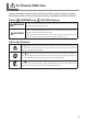
To Ensure Safe Use Improper handling or operation of this machine may result in injury or damage to property. Points which must be observed to prevent such injury or damage are described as follows. About WARNING and WARNING CAUTION Notices Used for instructions intended to alert the user to the risk of death or severe injury should the unit be used improperly. Used for instructions intended to alert the user to the risk of injury or material CAUTION damage should the unit be used improperly.
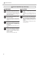
To Ensure Safe Use Incorrect operation may cause injury WARNING Keep children away from the machine. The machine includes areas and components that pose a hazard to children and may result in injury, blindness, choking, or other serious accident. Install in a location that is level and stable. Installation in an unsuitable location may cause an accident, including a fall or tip over. Never attempt to disassemble, repair, or modify the machine. Doing so may result in fire, electrical shock, or injury.
To Ensure Safe Use Danger of electrical short, shock, electrocution, or fire WARNING Connect to an electrical outlet that complies with this machine’s ratings (for voltage, frequency, and current). Incorrect voltage or insufficient current may cause fire or electrical shock. Never place any flammable object nearby. Never use a combustible aerosol spray nearby. Never use in any location where gases can accumulate. Combustion or explosion may be a danger.
To Ensure Safe Use Important notes about the power cord, plug, and electrical outlet Never place any object on top or subject to damage. Never allow to get wet. Never bend or twist with undue force. Never make hot. Never pull with undue force. Dust may cause fire. Never bundle, bind, or roll up.
To Ensure Safe Use The head area becomes hot WARNING Never touch the head immediately after printing has finished. Doing so may cause burns. Warning Label Warning label is affixed to make areas of danger immediately clear. The meaning of the label is as follows. Be sure to heed its warnings. Also, never remove the label or allow it to become obscured. Caution: High Temperature Never touch immediately after printing.
Important Notes on Handling and Use This machine is a precision device. To ensure the full performance of this machine, be sure to observe the following important points. Failure to observe these may not only result in loss of performance, but may also cause malfunction or breakdown. This Machine is a Precision Device. Handle carefully, and never subject the machine to impact or excessive force. Never print material outside the range of specifications.
About Operation Manuals Documentation Included with the Machine The following documentation is included with the machine. MPX-90M User’s Manual (this manual) This describes important notes for ensuring safe use, and explains how to install and operate the machine. It also explains how to install and operate included software. Be sure to read it first. METAZA Driver Online Help Roland METAZAStudio Online Help Roland SFEdit2 Online Help You view this documentation on your computer screen.
10
Chapter 1 Getting Started 1-1 About the Machine..................................................................12 Features.....................................................................................12 Names of Components...............................................................12 Checking the Included Items......................................................14 1-2 Installation...............................................................................15 Installation Environment........
1-1 About the Machine Features This machine is a direct marking printer. It prints images by striking detailed points using a marking pin mounted in a head. You can print Data Matrix ECC200 and QR codes on small steel objects used for medical purposes. Even when printing different multiple codes in a row, you can continue printing without stopping to enter data for each instrument to be imprinted (Variable Printing).
1-1 About the Machine Head (MPH-90) Printing is performed on material using with a marking pin. Diamond is attached to the tip of the marking pin. Since the head is a consumable part, replace it at an appropriate timing. P. 52, “Head Replacement” Marking pin Material Retainers Vise This is used to fix an instrument to be imprinted. P. 35, "STEP 1: Loading the Instrument to be Imprinted" Table, Adhesive sheet This is used to fix an instrument to be imprinted that cannot be secured using the vise.
1-1 About the Machine Checking the Included Items The following items are packed together with the unit. Make sure they are all present and accounted for.
1-2 Installation Installation Environment Install in a quiet, stable location offering good operating conditions. An unsuitable location can cause accident, fire, faulty operation, or breakdown. CAUTION Install in a location that is level and stable. Installation in an unsuitable location may cause an accident, including a fall or tip over. Never install in a location subject to wide fluctuations in temperature or humidity. Never install in a location subject to shaking or vibration.
1-2 Installation Power Cord Connection At this time, the connection to the computer must not be made yet. Failure to follow the correct procedure may make installation impossible. You make the connection to the computer when you install METAZA driver. P. 18, “Installing the Driver and the Software” WARNING Do not use with any electrical power supply that does not meet the ratings displayed on the AC adapter. Use with any other power supply may lead to fire or electrocution.
1-3 Installing the Software System Requirements Operating system * Windows XP/Vista/7 (32 bit edition/64 bit edition) Processor Intel® Core 2 Duo or greater (Core i5 or greater recommended) Memory 1 GB or greater (2 GB or more recommended) Optical drive CD-ROM drive Video card and monitor At least 16 bit colors (High Color) with a resolution of 1024 x 768 or more recommended Free hard-disk space required for installation 25 MB * As this software is a 32-bit application, it runs on WOW64 (or Wind
1-3 Installing the Software Installing the Driver and the Software Make sure to connect the machine to a computer by following the given procedure. Failure to follow the correct procedure may make installation impossible. Procedure Before you start installation and setup, make sure the USB cable is NOT connected. Log on to Windows as “Administrators.” Insert the Roland Software Package CD-ROM into the computer. Windows Vista/7: When the automatic playback window appears, click [Run menu.exe].
1-3 Installing the Software Windows Vista / 7: If the screen shown in the figure appears, click [Install this driver software anyway]. Windows XP: If the screen shown in the figure appears, click [Continue Anyway]. Follow the on-screen instructions and continue with the installation. When installation is complete, click Installation information for each software item will be displayed automatically as needed. in the installation menu.
1-3 Installing the Software Windows Vista / 7: The driver is installed automatically. Windows XP: Select [No, not this time], and then click [Next]. Select [Install the software automatically], and then click [Next]. Click [Finish]. If this screen appears during installation Click [Continue Anyway]. Remove the Roland Software Package CD-ROM from the computer, click [Back], and start over from the previous screen.
1-3 Installing the Software How to Open the METAZA Driver's Printing Preferences Screen Procedure From [start] menu ( ), click [Devices and Printers] (or [Printers and Faxes]). Right-click the [Roland MPX-90M] icon, and then click [Printing Preferences]. The METAZA driver's Printing Preferences screen opens.
1-3 Installing the Software How to Open the METAZA Driver Help Open the METAZA driver's Printing Preferences screen, and then click [Help]. P. 21 "How to Open the METAZA Driver's Printing Preferences Screen" How to Start The Software From start menu ( 22 ), click [All Programs] → [software you want to use] → [software you want to use].
1-3 Installing the Software How to display help for software Start the software, and then click [Help] → [Table of Contents] from the menu. P.
24
Chapter 2 Printing 2-1 Preparing for Printing..............................................................26 Getting Started: Checking Print Workflow..................................26 STEP 1: Switching On the Power...............................................27 STEP 2: Specifying Output Destination for METAZAStudio.......28 STEP 3: Preparing Instrument to be Imprinted...........................28 STEP 4: Preparing Print Data.....................................................30 2-2 Starting Printing.
2-1 Preparing for Printing Getting Started: Checking Print Workflow Preparing the MPX-90M machine Switch on the power of the machine and select it as the output destination for the computer. P. 27, "STEP 1: Switching On the Power," p. 28, "STEP 2: Specifying Output Destination for METAZAStudio" Preparing an instrument to be imprinted Check the several conditions for thickness, hardness, and the like that an instrument to be imprinted needs to meet. P.
2-1 Preparing for Printing STEP 1: Switching On the Power Procedure Stopper Open the cover and loosen the head's stopper. Tighten Press the Power/Movement button. The Head moves to the left rear, and the lamp of the Power/Movement button is turned ON. This operation is called initialization. Power/Movement button When the power lamp remains blinking An initialization error. Loosen the stopper of the head, and then press the Power/Movement button. The error is cleared, and the power lamp is lit.
2-1 Preparing for Printing STEP 2: Specifying Output Destination for METAZAStudio Procedure Start METAZAStudio. P. 22, "How to Start The Software" Click [File] → [Set up the printer]. The [Print Setup] dialog box appears. Select [MPX-90M]. Click [OK]. STEP 3: Preparing Instrument to be Imprinted The requirements for the instrument to be imprinted by the machine are described below. The instrument needs to meet all these requirements. Thickness 0.3 to 40 mm (0.012 to 1.5 in.
2-1 Preparing for Printing Hardness of surface to print Hardness of surface to print Vickers hardness (HV) of 200 or less Materials which may crack or split by printing (such as glass, stone, precious stones, china, and porcelain) cannot be printed even if hardness is within the preceding range. Attempting to print such materials may damage the machine. Vickers hardness (HV) is used as a yardstick to represents the hardness of industrial materials.
2-1 Preparing for Printing STEP 4: Preparing Print Data The method of preparing print data for [Variable Printing] is explained below. Variable Printing needs a CSV file. You can create a CSV file using database files. For information on creating a CSV file, contact the administrator of databases. What you print is [Text] or [2D Symbol]. "Data Matrix" or "QR code" is selectable as 2D symbol.
2-1 Preparing for Printing Click [OK]. In the case of [2D Symbol] Click and then . In the case of [Text] Click and then . Drag the mouse (move while holding down the left button of the mouse) diagonally downward on the work area* in METAZAStudio. [Variable Field] in which you can place [2D Symbol] or [Text] is created.
2-1 Preparing for Printing Click [Object] > [Move to Center]. The center of the Variable field moves to the center of the work area. This work is important, being related to the actual printing position. In the machine, the center in printing operation is defined as the reference point in printing operation. The "center of the work area" in METAZAStudio coincides with the reference point in printing operation.
2-1 Preparing for Printing Make the settings for properties including [Size] of the Variable field. The setting items you can specify are different between [2D Symbol] and [Text]. For details on each setting, refer to the help for METAZAStudio ([Commands]-[Object] menu-[Properties]-[Properties] dialog. P. 23, "How to Display Help for Software" [Properties] dialog box for 2D symbol [Properties] dialog box for text 2. After making the settings, click [OK].
2-1 Preparing for Printing Specify a CSV file and click [Open]. Drag and drop the column title of the imported CSV file into the [Variable Field] The specified CSV file is imported into METAZAStudio. [2D Symbol] or [Text] is displayed in the [Variable Field]. . If you want to change the size or location of You can display each symbol in turn by clicking the Variable Field or the cell size of the 2D symbol, open the [Properties] dialog box and change the settings. Now the print data is prepared.
2-2 Starting Printing STEP 1: Loading the Instrument to be Imprinted Decide whether you use the vise or table as a retainer depending on the size or shape of the instrument to be imprinted. The criteria used to select the vise or table are as follows: Vise The size and shape of the instrument that can be fixed by vise. Table The instrument has a flat bottom and the size and shape of the instrument that can not be fixed by vise. 1. Attach the head cap.
2-2 Starting Printing Attach a head cap to the tip of head. Hold the head. Mount it as lightly holding the head as shown in Tighten the figure. The head cap is attached correctly when its tab clicks. Head Head cap About the shape of head cap There are two different types of head caps with a different shape. Select the one appropriate for a printing surface. Flat bottom type This is suitable for printing on a flat surface.
2-2 Starting Printing 2. Load the instrument to be imprinted on the vise. When using the table, go to P. 40. Push the rear side of the vise (where the handle is placed) against the main unit. Align the sides of the vise with the alignment marks and lower the front side of the vise. When the tabs on the bottom of the vise fit into the holes on the unit, this completes mounting of the vise. Handle Alignment mark Turn the fine adjustment dial to align the sides of the layers of the table.
2-2 Starting Printing Raise the vise binder. When raising or lowering the binder, be sure to hold its handle. Handle Binder Place the instrument to be imprinted on the table of the vise and lower the binder. Follow the instructions below and determine the position of the instrument. The area to be imprinted must be within the resin sheet on the table. The area to be imprinted must be 10 mm (0.39 in.) or more away from the outline of the binder.
2-2 Starting Printing Press the laser pointer button. The laser pointer is irradiated. If the machine is idle for 5 minutes, the laser pointer is automatically turned off. Laser pointer button Raise the lock lever. Move the table so that the laser pointer points at the center of the area to be imprinted. To finely adjust the table position, use the fine adjustment dial. The table position is adjustable within the range of ± 2 mm (0.08 in.).
2-2 Starting Printing 2. Load the instrument to be imprinted on the table. When using the vise, go to P. 37. Set the table. Place the table by aligning it with the frame on the unit. When the tabs on the bottom of the table fit into the holes on the unit, this completes setting of the table. Table Table Affix the adhesive sheet for table to the table. Place the adhesive sheet straight inside the table frame by aligning it with the scale marks.
2-2 Starting Printing Load the instrument to be imprinted on the adhesive sheet. Move the table so that laser pointer points at the center of the area to be imprinted. Gently press the instrument to be imprinted in a way that you affix it to the adhesive sheet. If the instrument protrudes from the table and the instrument tilts, place a support in order to keep the instrument horizontal.
2-2 Starting Printing 3. Fix the height of the head. (Only when no head cap is used) Press the Power/Movement button. The head moves and stops at the position where the tip of the head cap rides on the surface of the instrument to be imprinted. Power/Movement button Loosen the head's stopper. Loosen Lower the stopper to the bottom. Fix the stopper. Align the center of the knob with the top of the triangle right below.
2-2 Starting Printing Press the Power/Movement button. The head moves to the left rear. Power/Movement button Detach the head cap. Support the head Head cap Putting your fingers on the projecting rim of the head cap eases removal. STEP 2: Making Prints After you complete "Preparing for Printing" and "Loading Instrument to be Imprinted," printing starts. P. 26, "2-1 Preparing for Printing," p. 35, "STEP 1: Loading the Instrument to be Imprinted" Procedure Click .
2-2 Starting Printing Set and confirm the preferences below. Printer name Roland MPX-90M Printing range To restrict records (individual data included in a set of data used in Variable Printing) to be printed, specify the record (page) that you wish to print. For example, if you print the records of 2nd to 5th only, select [Pages] and specify the "2nd" to "5th" pages. Copies If you imprint the same instrument at multiple locations, specify multiple number of copies.
2-2 Starting Printing Click [OK]. Printing of the next page starts. * Depending on the type of your scanner, it may be unable to read the 2D symbol imprinted by the machine, because it is unsuitable for the 2D symbol. For information on scanners suitable for the machine, consult your authorized Roland DG Corp. dealer or us. When you wish to print only the record being displayed: Click . The [Print] dialog box appears.
2-3 Finishing and Stopping Printing Operations Stopping Printing Operations Hold down the Power/Movement button for one second or longer. The light slowly blinks while the transmitted print data is being deleted. The light goes dark and the power is switched off. Power/Movement button Deleting Data from Print Queue Procedure Windows 7 From [start] menu ( and Printers]. Windows Vista From [start] menu ( Windows XP From [start] menu ( [Printers and Faxes].
Chapter 3 Maintenance and Adjustment 3-1 Maintenance and Adjustment.................................................48 Points to Note on Daily Care......................................................48 Cleaning the Body/Vise/Table.....................................................48 Cleaning the Adhesive Sheet.....................................................48 Cleaning of the Head Cap..........................................................48 3-2 Adjustment.........................................
3-1 Maintenance and Adjustment Points to Note on Daily Care WARNING Never use gasoline, alcohol, thinner, or any other flammable material. Doing so may cause fire. CAUTION Never touch the heads immediately after printing has finished. Doing so may cause burns. This machine is a precision device, and is sensitive to dust and dirt. Be sure to carry out day-to-day cleaning. Never use solvents such as thinner, benzine, or alcohol. Never attempt to oil or lubricate the machine.
3-2 Adjustment Adjusting the Striking Force of the Pin You can adjust the striking force of the pin by using MPX-90M Head Manager. Pin adjustment involves striking the pattern shown in the figure. Prepare a piece of test-use printing material (brass) or other material measuring about 60 mm (2.3 in.) by 60 mm (2.3 in.). Adjustment pattern Procedure Start MPX-90M Head Manager. P. 22, "How to Start The Software" Switch on the power to the machine. P.
3-2 Adjustment Adjustment of Origin Point If printed text or image is placed at a position that does not coincide with the desired position, the origin point of the machine is displaced. Adjust the origin point using the method described below. Procedure Start MPX-90M Head Manager. P. 22, "How to Start The Software" Click [Adjust Origin]. The [Adjust Origin] wizard appears. MPX-90M Head Manager Follow the on-screen instructions to perform adjustment.
3-3 The Replacement of the Consumable Parts The Replacement Cycle for the Head Cap When the head cap becomes worn away as shown in the figure below, it is time for replacement. Replace the head cap with a new one appropriately. The degree of wear may vary according to printing conditions.
3-3 The Replacement of the Consumable Parts Head Replacement In the following cases, the head needs replacement. The head reaches the end of its life. The marking pin is worn out. A General Guide of Head Life About 4,000 plates can be printed under the following conditions. Material used : MD-NI (Roland nickel-plated plate) Printing area : 30 mm (1.1 in.) X 23 mm (0.9 in.
3-3 The Replacement of the Consumable Parts Switch on the power to the machine. P. 27, "STEP1: Switching On the Power" The indicator for [The amount of Pin usage] in MPX90M Head Manager shows how much the marking pin has been used. The following cases need head replacement. The indicator is shown in red. Though the indicator is not shown in red, attractive printing is unavailable or images are uneven.
3-3 The Replacement of the Consumable Parts Switch on the power to the machine. P. 27, "STEP1: Switching On the Power" Click [Replace Head]. Follow the on-screen instructions to perform adjustment for the pin. Set a material to be imprinted with a test pattern using the adhesive sheet and table. Use a head cap. P. 35, "STEP 1: Loading the Instrument to be Imprinted" If the adjustment pattern fails to be printed, see the sections given below. P.
Chapter 4 Appendix 4-1 More Advanced Operations....................................................56 Directly Creating 2D Symbol......................................................56 Registering a Composition and Adjusting the Striking Force.....59 Changing Basic Settings of METAZA Driver...............................60 Creating and Editing Line Text....................................................61 Other operations available with METAZAStuido.........................65 4-2 What to Do If...........
4-1 More Advanced Operations Directly Creating 2D Symbol You can create 2D symbol not only from a CSV file but also directly from METAZAStudio. Based on a 2D symbol you create, you can edit the code using METAZAStudio and create another 2D symbol. Procedure Start METAZAStudio. P. 22, "How to Start The Software" If METAZAStudio is running, click . In the [Select Material] dialog box, select the material of the instrument to be imprinted.
4-1 More Advanced Operations Drag the mouse (move while holding down the left button of the mouse) diagonally downward on the work area* in METAZAStudio. The drawing area for a 2D symbol is created and the [Code Input] dialog box appears. * Work area = black area on the screen Enter a code and click [OK]. Click [Object] > [Move to Center]. Enter a code for the 2D symbol. The center of the 2D symbol moves to the center of the work area.
4-1 More Advanced Operations Click . The [Properties] dialog box appears. If the drawing area for the 2D symbol is not selected, you cannot click and then click (select) the drawing area for the 2D symbol. . If you cannot click , click Make the settings for properties including [Size] of the 2D symbol. For details on each setting, refer to the help for METAZAStudio ([Commands] - [Object] menu - [Properties] - [Properties] dialog box). P.
4-1 More Advanced Operations Registering a Composition and Adjusting the Striking Force With the machine, performing printing using a striking force appropriate to the material of the instrument to be imprinted can obtain printing results of even higher quality. The METAZA driver for the machine has premade settings for a number of materials and their appropriate striking forces, but you can also register materials and their optimal striking forces yourself.
4-1 More Advanced Operations Enter a name for the composition you’re registering. Enter [Speed/Impact] The printing results vary according to the hardness of the material. Adjust to match the material. METAZA Driver online help ("[Correction] tab" > "[Details] dialog box") Impact--MIN You can set the minimum value of print impact for an image. Raise the value when dark areas of the image are not struck.
4-1 More Advanced Operations Right-click the [Roland MPX-90M] icon, Click [Printing Preferences]. The setting window for METAZA Driver appears. Change the settings to suit your needs. After completing the setting, click [OK]. Description METAZA Driver allows you to make the basic settings for a variety of items including the size of material and the unit used for display. The basic settings continue to be applied by making the settings with the method described above.
4-1 More Advanced Operations Creating and saving stroke character fonts Procedure Start SFEdit2. P.23, “How to Display Help for Software“ Click [File] → [New…]. Select a font which is used as a base of a stroke character font to be created. Click [OK]. [Select Base Font] dialog box appears. A stroke character font is automatically created. Click Enter the "name of the created stroke character. " . [Save] dialog box appears.
4-1 More Advanced Operations Click . Using a stroke character font in METAZAStudio Make sure that either of the following operations are completed in advance. Create a stroke character font before SFEdit2 is installed. The window shown in the figure appears when you install it. If you did not create a stroke character font at the time of installation, reinstall SFEdit2 and create a stroke character font. P. 18, "Installing the Driver and the Software," p.
4-1 More Advanced Operations Clikck [Format] tab. Select [RSF]. The option of [Font] becomes Stroke character only. Select Stroke character. Click [OK]. Entered characters are changed into stroke characters. The stroke character font selected in for the stroke characters. 2. Editing Stroke character Click . Click the stroke character you want to edit. Eight pointers appear around the stroke character. Click [Edit] → [Stroke Font] → [Edit Stroke…]. SFEdit2 starts.
4-1 More Advanced Operations From Character List, click stroke character you want to edit. The stroke character you want to edit is displayed in the virtual body and the stroke character becomes editable. Change the position and shape of the stroke character. Help for SFEdit2 (Editing Polylines) Character List Click . The edit is overwritten to the selected stroke character font. Click . SFEdit2 is finished. The edit is reflected to the stroke character.
4-2 What to Do If The [Power/Movement] button is blinking. Do you switch on the power as the height of the head position is fixed? As the power is switched on while the height of the head position is fixed, the initial operation is stopped. If the machine continues the initial operation while the instrument to be imprinted is loaded, the instrument's surface may be scratched and/or the marking pin may be damaged. Loosen the knob counterclockwise once.
4-2 What to Do If Do you set an instrument to be imprinted without using the supplied vise or the table? Switch off the power by holding down the [Power/Movement] button for one second or longer. If you set an instrument of which surface height is low without using the supplied table or the vise, the machine considers that the surface height of the instrument does not meet the requirement for carrying out printing operation. Make sure to set an instrument using the supplied vise or the table. P.
4-2 What to Do If Striking is performed, but nothing is printed. Does the instrument to be imprinted meet the requirements for instruments that can be imprinted? Prepare and use an instrument that can be imprinted. P. 28, "STEP 3: Preparing Instrument to be Imprinted" If you’re not using a head cap, does the head position match the surface height of the instrument to be imprinted? Check if the head position matches the surface height of the instrument in the case that you do not use the head cap.
4-2 What to Do If The printed image is unattractive. Are the settings for the material correct? Choose the material of the loaded instrument in METAZAStudio. Even if the composition of the material is the same, the hardness of the printed surface may vary greatly depending on the casting method, the composition of impurities, the presence of plating, and so on. In such cases, fine adjustment of the striking force is necessary. P.
4-2 What to Do If Is the image darkness uneven? Performing overstriking may improve the image quality. With the instrument left loaded, try performing overstriking with different settings for [Gamma], [Brightness], or [Contrast] in the preview window. METAZAStudio online help>“Commands” >[File] menu>Print Preview Was bidirectional printing performed? Bidirectional printing can shorten the printing time, but the image quality may suffer.
4-2 What to Do If Right-click the "Roland MPX-90M" icon, and then click Printing Preferences. The METAZA driver's Printing Preferences screen opens. Click [Test Print] in the [Option] tab. The test pattern is printed on the material. Use the scale to read and note down locations where the test pattern is not continuous or not visible. Back Note down the values in all four directions (front, back, left, and right).
4-2 What to Do If Select [Correct slope] Enter the scale values you noted in into the driver. Click [OK]. To install METAZA driver separately You can install the driver and software at a time. For the method of installing them at a time, see P. 18, "Installing the Driver and the Software”. Procedure Log on to Windows as an administrator or as a member of the Administrators group. Insert the Roland Software Package CD-ROM into the computer.
4-2 What to Do If Click [Install] of "METAZA Driver". Select [Install], select [Roland MPX-90M] as the model name, select [USB] as the port, and then click [Start]." Driver installation starts. Follow the on-screen instructions and continue with the installation. Windows Vista or 7 If the screen shown here is displayed, click [Install this driver software anyway]. Windows XP If the screen shown here is displayed, click [Continue Anyway].
4-2 What to Do If When the screen shown here is displayed, click [finish]. Click of the setup menu. Remove the CD-ROM from the CD-ROM drive. Connect the machine and the computer with a USB cable. Please use the included USB cable. Do not use a USB hub. Windows Vista or 7 The driver will be installed automatically. Windows XP Select [No, not this time] and click [Next]. Select [Install the software automatically] and click [Next].
4-2 What to Do If Click [Finish]. If the following screen is displayed during installation Click [Continue Anyway]. Eject and remove the CD-ROM, and then click [Back] and repeat from the last screen.
4-2 What to Do If To Install Software Separately You can install the driver and software at a time. For the method of installing them at a time, see P. 18, "Installing the Driver and the Software”. Procedure Log on to Windows as an administrator or as a member of the Administrators group. Insert the Roland Software Package CD-ROM into the computer. (Windows Vista/7 only: When the automatic playback window appears, click [Run menu.exe].) The setup menu appears automatically.
4-2 What to Do If The METAZA Driver Cannot Be Installed If the driver installation stops partway through or if the wizard does not appear when you use a USB cable to connect the PC to the machine, follow the appropriate procedure shown below. Windows 7 1. Use a USB cable to connect the machine and the PC, and then turn the machine on. 2. If the Found New Hardware wizard appears, click [Cancel] to close it. Disconnect any USB cables for printers other than this machine. 3.
4-2 What to Do If 3. On the taskbar, click [Start], and then right-click [My Computer]. Click [Properties]. 4. Click the Hardware tab, and then click [Device Manager]. The Device Manager window appears. 5. Click [Show hidden devices] on the View menu. 6. Double-click [Printers] or [Other devices] in the list. Click the model name or [Unknown device], whichever appears below the item you selected. 7. Click [Delete] on the Action menu. 8. In the Confirm Device Uninstall dialog box, click [OK]. 9.
4-2 What to Do If 6. On the task bar, click [Start], [All Programs], [Accessories], [Run], and then [Browse]. 7. Choose the name of the drive or folder where the driver is located.* 8. Select "SETUP.EXE," click [Open], and then click [OK]. 9. When the User Account Control dialog box appears, click [Allow]. The driver's setup program starts. 10. Click [Uninstall]. Select the machine that you want to uninstall, and then click [Start]. 11.
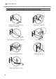
4-3 When Moving the Machine Attaching retainers When moving the machine, be sure to attach the retaining materials. Moving the machine without attaching the retaining materials may result in damage to the machine. Procedure Switching on the power. P. 27, "STEP 1: Switching On the Power" Remove the vise (or the table). Attach the head cap. Hold the head. Head Head cap Switching off the power. P.
4-3 When Moving the Machine Fix the head at the highest position. After loosening the knob, lift the head to the highest position and tighten the knob. Loosen Tighten The center of the knob must be positioned immediately above the top of the triangle. Head Lift the head. Remove the power cord and USB cable. Attach the retaining materials. Secure the machine at three points (with 5 screws). Attach all the retainers and wind up the screws with the provided hexagonal wrench.
4-4 Main Unit Specifications Printable Area Vise Binder Unprintable area Printable area Unprintable area Printable area * The 10 mm area from the binder of the vice is unprintable because the head comes into contact with the binder. Table Top view of the table Center line Center line Maximum Printable Area 80 mm × 80 mm (3.1 in. × 3.1 in.) "The setting by METAZA Driver is required. If an image exceeds the printable area, the print result might become uneven in the outside of the printable area.
4-4 Main Unit Specifications Location of Power Rating and Serial Number Label Rear Serial number This is required when you seek maintenance or support. Never remove the label. Power rating Use an electrical outlet that meets the requirements for voltage, frequency, and amperage given here. AC adapter Power rating Use an electrical outlet that meets the requirements for voltage, frequency, and amperage given here.
4-4 Main Unit Specifications Specifications Printable material Loadable material size Printing area Resolution Printing direction Printing speed (Default) Interface Power requirements Power consumption Acoustic noise level Operation temperature Operation humidity External dimensions Weight Accessories MPX-90M Gold, silver, copper, platinum, brass, aluminium, iron, stainless steel, etc. (Vickers hardness [HV] of the printing surface must be 200 or less.
85
86
87
88
R1-111229