
User`s manual


2
1 cut 50Cm/s
0.250mm 30gf
Display
Provides menu display, configuration
preferences, coordinates, as well as
error messages for troubleshooting.
2-3 Operation Panel
MENU Key
MENU
Employed to select among the
available menus, or to cancel the
making of a setting at a particular
menu.
Cursor Keys
Used to move the blinking cursor. The
and keys are also used to
move the material, and the
and
keys are used to move the tool
carriage.
ENTER Key
ENTER
Press to enter into a subroutine of the
item selected using the cursor keys or
to confirm (save) the value set in
configuration.
TEST Key
TEST
Pressed to execute a cutting test (Use
to confirm material specifications as
well as cutting speed, blade force, and
blade compensation).
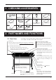
SETUP Key
SETUP
Pressing this key after loading a material causes the
material's cutting range to be determined automatically.
Blinking Cursor
Used to select the desired item from the menu. The
key moves it
to the right, the
key moves it to the left, the key moves it up,
the
key moves it down.
Power LED
This lights up when the power is
switched on.
SETUP LED
This lights up when the
SETUP
key is
pressed to pause the PNC-1860/1410/
1210.
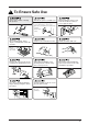
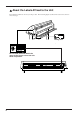
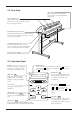
2-2 Rear View
Sheet Loading Lever
When loading media, lift this lever to lower to
pinch rollers. To removing media, lower this
lever to raise the pinch roller.
Parallel (Centronics) Connector
In a parallel configuration, this connector is where you
need to connect the parallel cable in order to commu-
nicate with your computer.
Serial (RS-232C) Connector
In a serial configuration, this connector is
where you need to connect the serial cable that
is used to communicate with your computer.
Power Connector [AC IN]
This jack accepts a standard AC power cord.
Sheet Sensor
When a material is passed through this
portion, this sensor detects the material's
cutting range.