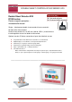
DOUBLE SHEET CONTROL R1000 SERIES E20 Pos : 1 /D oppelbl ec h/Geräte/E20/Dec kbl att/D ec kbl att @ 1\mod_1192448868578_501.doc @ 5029 Double Sheet Detector E20 R1000 series Electro magnetic principles – microcontroller based Single – sided contact double sheet control of ferrous materials No force after measurement Double sheet control of 0.1 to 6.5 mm (.004 to .255 in.
Copyright © 2007 ROLAND ELECTRONIC GmbH Otto-Maurer-Str. 17 DE 75210 Keltern All rights on this document are at Roland Electronic GmbH. Reproduction (also partly), electronical coverage, translation, transmission to third parties, only with our prior permission. Subject to change without further notice.
Manual Double Sheet Detector R1000 series E20 B0046991 / Rev. 1.6 Table of contents Declaration of conformity according to EC directives .....................................................................................7 1 Safety advices ........................................................................................................................................9 1.1 Safety instructions and warnings for user ...................................................................................
Manual Double Sheet Detector R1000 series E20 Table of contents 4.3.7 Incorrect mounting of the P sensors .......................................................................................... 60 4.3.8 Electromagnetic interference ..................................................................................................... 61 5 Electrical installation............................................................................................................................63 5.
Manual Double Sheet Detector R1000 series E20 B0046991 / Rev. 1.6 Table of contents 6.4 Internal control (Demo mode) .........................................................................................................93 6.5 Serial interface RS232 (version C only)..........................................................................................94 6.5.1 Transmission parameters ...........................................................................................................94 6.
Manual Double Sheet Detector R1000 series E20 Table of contents 10.5 Short description RPP-XP software ............................................................................................. 126 10.6 Spare parts ................................................................................................................................... 126 11 Technical records...............................................................................................................................
Manual Double Sheet Detector R1000 series E20 B0046991 / Rev. 1.6 Safety advices Pos : 1 /Komponenten allgemein/Leers eite @ 0\mod_1165223317234_501.doc @ 2343 @ @ 1 Pos : 2 /Komponenten allgemein/EG- Konfor mitäts er klärung 115/230V AC @ 0\mod_1173707333875_501.doc @ 3827 @ @ 1 Declaration of conformity according to EC directives Manufacturer: Roland Electronic GmbH Otto-Maurer-Str.
Manual Double Sheet Detector R1000 series E20 B0046991 / Rev. 1.6 Safety advices Blank page Pos : 4 /Kapitelübersicht/01. Sic herheits hinweise @ 0\mod_1121421059859_501.doc @ 505 @ 1 @ 1 8 ROLAND ELECTRONIC GmbH · Otto-Maurer-Str.
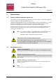
Manual Double Sheet Detector R1000 series E20 B0046991 / Rev. 1.6 1 Safety advices Safety advices Pos : 5 /Komponenten allgemein/Sic her heitshi nweis e @ 0\mod_1127211035609_501.doc @ 613 @ 2 @ 1 1.1 Safety instructions and warnings for user This handbook contains all information required for the correct operation of the Roland equipment. It has been written for technically qualified personnel.
Manual Double Sheet Detector R1000 series E20 B0046991 / Rev. 1.6 Safety advices 1.3 Intended use Flexible Manufacturing Systems in the sheet processing industry require reliable Double Sheet Control systems in order to protect presses and other sheet processing machines against damage caused by feeding multiple sheets. The Double Sheet Detector R1000 E20 was specifically developed for this technical environment.
Manual Double Sheet Detector R1000 series E20 B0046991 / Rev. 1.6 2 Technical data Technical data Pos : 9 /D oppelbl ec h/Geräte/E20/2 Technisc he Daten/Ger ätedaten E20 @ 1\mod_1216127864218_501.doc @ 6465 @ 2 @ 1 2.1 Technical data control unit E20 Operating voltage: Power consumption: Switch on current: External fuse: Weight: Ambient temperature: 24 VDC, +6 V / -2 V 120 W (operation: <120 W with P42A, in idle: <10 W) 10 Amps for 1 ms 5 Amps medium time lag approx. 1.2 kg (2.
Manual Double Sheet Detector R1000 series E20 B0046991 / Rev. 1.6 Technical data Attention • In case of inductive load a coil protection diode should be used. Otherwise the signal output could be destroyed by the excess voltage generated by switching the inductive load off.
Manual Double Sheet Detector R1000 series E20 B0046991 / Rev. 1.6 2.2 Technical data Versions of the control unit E20 The control unit article key is coded as follows: 1. Control unit E20 for connection of one sensor A: = Control unit E20-x-x-FP A B B: = Version B C C: = Outputs O: Opto coupler R: Relay D C D: = Control unit in front panel enclosure 2. Control unit E20 for connection of up to four sensors, all sensors are plug connected directly at the unit.
Manual Double Sheet Detector R1000 series E20 B0046991 / Rev. 1.6 Technical data 2.3 Sensors The sensor description has the following code: A = Electro magnet B = Diameter C = Model* D = Thread E = Quick disconnect P42AGS A B C D E *Model: V: extended thickness measuring range A: stands for a larger air gap Fig. 1: Designation of sensors Pos : 12 /D oppel blech/Sensor en/P-Sensor en/P30/P30GS T ec hn. D aten @ 1\mod_1304686037382_501.doc @ 9169 @ 3 @ 1 2.3.
Manual Double Sheet Detector R1000 series E20 B0046991 / Rev. 1.6 2.3.2 Technical data Sensor P42AGS P42AGS P42AGS P42AGS with straight cable plug with 90° angled cable plug All dimensions are in mm. Length tolerance ± 0.8 mm, all other dimensions ± 0.2 mm Fig. 3: Sensor P42AGS Technical data Measuring range 2): Ambient temperature: Class of protection: Weight: Sensor cable: 1) 2) 0.2 – 4.0 mm 0 – 60 °C IP65 ca. 0.42 kg pluggable .01 - .16 inch 30 – 140 °F 0.
Manual Double Sheet Detector R1000 series E20 B0046991 / Rev. 1.6 Technical data 2.3.3 Sensor P75VGS P75VGS P75VGS with straight cable plug P75VGS P75VGS Top view with 90° angled cable plug All dimensions are in mm. Length tolerance ± 0.8 mm, all other dimensions ± 0.2 mm Fig. 4: Sensor P75VGS Technical data Measuring range 2): Ambient temperature: Class of protection: Weight: Sensor cable: 1) 2) 3) 0.2 – 6.5 mm (.004 - .25 inch) 0 – 60 °C IP65 ca. 1.65 kg pluggable 0.2 – 8.0 mm (.008 - .
Manual Double Sheet Detector R1000 series E20 B0046991 / Rev. 1.6 2.4 Technical data Sensor performance data (Measuring time) In the following diagram the response time of the control unit for measurement is shown depending in sensor type and number of sensors activated by the program. In addition the response time depends on the selected system parameter “measure”, the actual sheet thickness, the nominal sheet thickness and the upper limit (up).
Manual Double Sheet Detector R1000 series E20 B0046991 / Rev. 1.6 Technical data Note The sensor diagrams shown here are valid for systems with Hardware Version 5 and higher (from system no. 103237, from date 27.02.2006). Having the “old” sensor diagrams (before HW version 5) available could be useful, e.g. for exchanging control units with “old” / “new” Hardware versions). For this reason the “old” sensor diagrams are shown in the appendix.
Manual Double Sheet Detector R1000 series E20 B0046991 / Rev. 1.6 Technical data Measuring time P42AGS (Device-Hardware-Version 5 and higher) 380 370 4 sensors 360 P42AGS 350 150 % 120 % 340 330 320 310 300 290 280 270 3 sensors 260 250 System reaction time [ms] 240 230 220 210 200 190 180 170 2 sensors 160 150 140 130 120 110 100 90 80 70 1 sensor 60 50 40 0 1,0 1,5 2,0 2,5 3,0 3,5 4,0 Single sheet thickness (Nominal thickness) [mm] Standard working range Fig.
Manual Double Sheet Detector R1000 series E20 B0046991 / Rev. 1.
Manual Double Sheet Detector R1000 series E20 B0046991 / Rev. 1.6 Technical data Double sheet thresholds above 120% reduce the performance of the system with regard to air gaps between the sheets and increase the systems reaction time according to the diagram. Air gaps influence the performance negatively because air has - in contrast to steel - a high resistance to the magnetic flux. Therefore, air gaps reduce the performance of the system considerably (see chapter “3.
Manual Double Sheet Detector R1000 series E20 B0046991 / Rev. 1.6 Technical data 2.5 Sensor cables Suitable cable types: 2 • Oilflex FD810CY 2 x 1mm • Unitronic FDCP (TP) plus 1 x 2 x 1mm (UL / CSA) 2 2 ROLAND ELECTRONIC uses according to standard the oilflex FD810CY 2 x 1mm cable.
Manual Double Sheet Detector R1000 series E20 B0046991 / Rev. 1.6 Technical data Cable shields must be connected according to the wiring diagram (For details refer to chapter 5.4) and should have no additional connections. Note Damaged cable isolation can cause further (unwanted) electrical connections. Instruction: Leading a cable through EMC gland • Remove outer PVC sheath and shield but leave enough length for sheath and leads.
Manual Double Sheet Detector R1000 series E20 B0046991 / Rev. 1.6 Technical data 2.5.1 Sensor cables for direct connection of sensor 2.5.1.1 Cable CPM12S for sensors P30GS and P42AGS to sensor / to cable extension Cable socket Receptacle contact 1) 55 1) 1 2 3 4 5 1 2 4 3 to control unit Bootlace ferrules black (1) [white] black (2) [brown] Ø 20 OILFLEX FD810CY 2 x 1 mm² [Unitronic FDCP (TP) plus 1 x 2 x 1 mm² (UL / CSA)] View contact side black (1) [white] black (2) [brown] N.C. N.C.
Manual Double Sheet Detector R1000 series E20 B0046991 / Rev. 1.6 2.5.1.2 Technical data Sensor cable CPS for sensors P36GS, P42GS, P75GS and P75VGS to sensor Cable socket to control unit Bootlace ferrules Receptacle contact 1) 78 2 3 1 6 black (1) [white] black (2) [brown] 4 5 1) OILFLEX FD810CY 2 x 1 mm² [Unitronic FDCP (TP) plus 1 x 2 x 1 mm² (UL / CSA)] View contact side 1 2 3 4 5 6 N.C. N.C. N.C. N.C.
Manual Double Sheet Detector R1000 series E20 B0046991 / Rev. 1.6 Technical data 2.5.2 Sensor cable extensions A sensor cable extension can be relatively easy made. For this a CPM12S-G cable is always needed. In addition, depending on the sensor, either the following cables SM12CPM12SGG/SM12CPM12S-GW for P30GS and P42AGS or SM12CPS-GG/SM12CPS-GW for P36GS, P42GS, P75GS and P75VGS 2.5.2.
Manual Double Sheet Detector R1000 series E20 B0046991 / Rev. 1.6 2.5.2.2 Technical data Sensor cable extension SM12CPS for P36GS, P42GS, P75GS and P75VGS to sensor Cable socket to cable extension Cable plug Receptacle contact 1) Plug contacts 1) 78 2 62 3 4 Ø 20 5 1 1) OILFLEX FD810CY 2 x 1 mm² [Unitronic FDCP (TP) plus 1 x 2 x 1 mm² (UL / CSA)] View contact side 1 2 3 4 5 6 5 3 6 N.C. N.C. N.C. N.C.
Manual Double Sheet Detector R1000 series E20 B0046991 / Rev. 1.6 Technical data Blank page 28 ROLAND ELECTRONIC GmbH · Otto-Maurer-Str.
Manual Double Sheet Detector R1000 series E20 B0046991 / Rev. 1.6 3 System description System description Pos : 18 /D oppel blech/Geräte/E20/3 Sys tembeschr eibung/Sys tembesc hreibung - allgemein @ 0\mod_1192448592921_501.doc @ 4730 @ @ 1 Flexible production systems in the sheet processing industry require automated, reliable double sheet detection in order to protect presses and other processing machinery from damage by multiple sheets.
Manual Double Sheet Detector R1000 series E20 B0046991 / Rev. 1.6 System description 3.2 General hints for process security The process security of the system is influenced by the following factors: • the stability of the measuring values • the setting of under-gauge threshold and over-gauge threshold • the evaluation of the status signals Stable measuring conditions will result in stable measuring results.
Manual Double Sheet Detector R1000 series E20 B0046991 / Rev. 1.6 3.3 System description Control unit The E20 is based on the product platform R1000.
Manual Double Sheet Detector R1000 series E20 B0046991 / Rev. 1.6 System description 3.4 Parameters of the control unit The E20 provides for extensive configuration. So, different customer requirements can be served. Configuration is performed by setting system parameters and program parameters. System parameters are set only once on commissioning, and will then remain unchanged. Program parameters contain items which are material and job depending, and enable individual adaptation to the measuring task.
Manual Double Sheet Detector R1000 series E20 B0046991 / Rev. 1.6 System description “CLR parameter (Clear Program Parameter)“ Deletes all program parameters. For doing so, the parameter needs to be set to “yes“. Executing the command requires several minutes, since the program memory will completely cleared. All program parameters will be reset to the default values and existing teach-in data will be deleted. Using this function only makes sense if a unit is to be newly used for another machine.
Manual Double Sheet Detector R1000 series E20 B0046991 / Rev. 1.6 System description 3.4.2 Program parameters The sensor is operated with an electro magnetical method – called “P“ measurement. For the P measurement a compensation curve for linearization exists. The compensation curve fits to ST37 steel. Other steel alloys resp. magnetical materials deviate from this curve. This causes measuring results which can deviate for more than 5% from the real sheet thickness.
Manual Double Sheet Detector R1000 series E20 B0046991 / Rev. 1.6 System description “Zero adjust“ Before commissioning a new system, after having exchanged a sensor or a sensor cable or a control unit, a zero adjust must be performed. This zero adjust eliminates the variation of the sensors. The sensors can be zero adjusted “separately“ or “all in one stroke“.
Manual Double Sheet Detector R1000 series E20 B0046991 / Rev. 1.6 System description 3.5 Application samples The following are two typical application examples for the use of the E20. If more than one sensor is required, then the E20-4P is a good choice. Four sensors of the same type can be connected to this control unit. These sensors cannot be operated simultaneously, but only sequentially.
Manual Double Sheet Detector R1000 series E20 B0046991 / Rev. 1.6 System description Method a) Meaningful, if the sheets to be monitored by the various sensors have different sheet thicknesses. Also suitable if the nominal thickness changes from cycle to cycle. For this procedure the respective parameter set (program) must contain nominal thickness and sensor number. The selection of the program is then performed by the PLC.
Manual Double Sheet Detector R1000 series E20 B0046991 / Rev. 1.6 System description Method b) Advantageous when measuring the same sheet thickness with each sensor. Each measurement sensor is addressed via the inputs A/B of the control unit. In addition, the result of each measurement is available as output. Note Advantage: Substantial time saving compared to program switching. Program Thickness Sensor 1 0.
Manual Double Sheet Detector R1000 series E20 B0046991 / Rev. 1.6 System description Method c) Advantageous when measuring the same sheet thickness with each sensor. In contrast to the method b) addressing of each sensor is done automatically by the E20. The sequence of the sensors is predetermined in the program. Note Advantage: Very fast measurements are possible, smaller software effort on the PLC side. Only one output is generated for connected sensors.
Manual Double Sheet Detector R1000 series E20 B0046991 / Rev. 1.6 System description In addition to the selection by sensor number (see “11.
Manual Double Sheet Detector R1000 series E20 B0046991 / Rev. 1.6 4 Mounting Mounting Pos : 26 /D oppel blech/Geräte/E20 Bus/4 M ontage/Montage - Allgemeine Hi nweis e @ 0\mod_1173695080093_501.doc @ 3424 @ 2 @ 1 The mounting of the Double Sheet Detector R1000 E20 determines the measurement accuracy and the reliability of operation. The system was designed for operating in rough industrial environments.
Manual Double Sheet Detector R1000 series E20 B0046991 / Rev. 1.6 Mounting 4.2 Dimensions of the system 4.2.1 System in industrial enclosure Version E20 for one sensor (standard version) RS232 SPS PG16 Power PG9 M6 76 Sensor PG11 EMV 53 25 15 35 70 105 125 Befestigungsbohrungen für Schrauben M4 Mounting holes for screws M4 23 140 129 102,75 140 All dimensions are in mm. Tolerance: ±0.2 mm Fig.
Manual Double Sheet Detector R1000 series E20 B0046991 / Rev. 1.6 Mounting Version E20-4P for up to four sensors RS232 SPS PG16 Power PG9 M6 76 Sensor 1 Sensor 2 Sensor 3 Sensor 4 PG11 EMV PG11 EMV PG11 EMV PG11 EMV 53 30 15 20 50 80 106 132 158 173 Befestigungsbohrungen für Schrauben M4 Mounting holes for screws M4 All dimensions are in mm. Tolerance: ±0.2 mm Fig. 15: Dimensions of the wall mount enclosure - front view ROLAND ELECTRONIC GmbH · Otto-Maurer-Str.
Manual Double Sheet Detector R1000 series E20 B0046991 / Rev. 1.6 Mounting 4.2.2 System with enclosure for front panel mounting 160 180 (identically for one and four sensors) 4 x Ø 4,2 for Philips head screw M4 DIN 74 160 180 All dimensions are in mm. Tolerance: ±0.2 mm Fig. 16: Dimensions of the front panel enclosure -front view 44 ROLAND ELECTRONIC GmbH · Otto-Maurer-Str.
Manual Double Sheet Detector R1000 series E20 B0046991 / Rev. 1.6 Mounting Lateral view Freiraum für Kabel Mounting space All dimensions are in mm. Tolerance: ±0.2 mm Fig. 17: Dimensions of the front panel enclosure -lateral view Pos : 28 /D oppel blech/Geräte/E20 Bus/4 M ontage/Sensor montag e @ 0\mod_1173693761984_501.doc @ 3414 @ 2 @ 1 ROLAND ELECTRONIC GmbH · Otto-Maurer-Str.
Manual Double Sheet Detector R1000 series E20 B0046991 / Rev. 1.6 Mounting 4.3 Mounting of sensors The reliable function of the Double Sheet Detector depends to a great degree on the correct mounting of the sensors. The following mounting rules should be followed: • The sensor must be mounted perpendicular to the sheet and fully contact the sheet surface. Foreign matter should not obstruct the contact. • Tilting or air gaps between the sensor and the sheet surface can result in faulty measurements.
Manual Double Sheet Detector R1000 series E20 B0046991 / Rev. 1.6 4.3.1 Mounting Checklist for Mounting of contacting Sensors In the interest of longest lifetime and operational security the following items should be observed when mounting contacting sensors and checked in regular intervals. Point of attention Possible influences Cable type 1 Use only the recommended cable with highest flexibility and durability. Cable routing 2 Avoid any tension of the cable.
Manual Double Sheet Detector R1000 series E20 B0046991 / Rev. 1.6 Mounting 4.3.2 Spring loaded sensor bracket P-sensors should always be fitted into spring mounted sensor bracket rather than rigid mounting arrangements. A substantial advantage is in the fact that the sensor present itself perpendicular to the sheet metal surface even though sensor bracket and sheet surface may not be completely aligned at a right angle. It is important to observe that lateral cable pull does not tilt the sensor.
Sensor clamping For inclined sheet stacks Suction delay time ** Note Application Characteristics: For vertical destackers For robot destackers and high speed linear destackers Spring travel Weight Pressure force on sheet Suction cup diameter Vacuum feed Spare parts Total height * Sensor mounting Mounting Fits to Description Type no For narrow sheets and applications where weight is critical 2 nuts M42 + -- 29 mm 0.6 kg 48 N n.a. n.a.
Manual Double Sheet Detector R1000 series E20 B0046991 / Rev. 1.6 Mounting 4.3.2.1 Spring loaded sensor bracket SH42GS "A" 10Ø 98 6 57 6 Hub max. 65 min. 25 movable fixed Sensor View in direction "A" without sensor 90 O ° 45 80 40 75 ° 30 12 0° ø20.5 50 110 All Dimensions are in mm. Tolerance: ±0.4 mm. Fig. 19: Spring loaded sensor bracket SH42GS 50 ROLAND ELECTRONIC GmbH · Otto-Maurer-Str.
Manual Double Sheet Detector R1000 series E20 B0046991 / Rev. 1.6 4.3.2.2 Mounting Spring loaded sensor bracket SH75GS "A" 10Ø 98 6 54 6 Hub max. 65 min. 25 movable fixed Sensor View in direction "A" without sensor 120 ° .7 66 45° = 75° 20,5 19 x 45° 44.5 x 45° R 152.5 R = 42 .5 10.5 152.5 All Dimensions are in mm. Tolerance: ±0.4 mm. Fig.
Manual Double Sheet Detector R1000 series E20 B0046991 / Rev. 1.6 Mounting 4.3.3 Spring loaded sensor bracket with flat suction cup Destacking of blanks is done mostly with the vacuum suction cups. For the measurement of the sheet thickness the sensors should rest vertically and flat on the sheet. The best contact to the sheet surface is made by mounting the sensor into a vacuum suction cup.
Manual Double Sheet Detector R1000 series E20 B0046991 / Rev. 1.6 Spring loaded sensor bracket SHS42GS with flat suction cup The spring loaded sensor bracket SHS42GS with flat suction cup is intended for accommodating the sensors. It is well suitable for use in feeder destacking applications (only vertical motions, no turning motions). For usage with robotic destackers the sensor bracket SHS42G-FB (with bellow suction cup) is to be preferred.
Manual Double Sheet Detector R1000 series E20 B0046991 / Rev. 1.6 Mounting 4.3.3.3 Spring loaded sensor bracket SHS75GS with flat suction cup The spring loaded sensor bracket SHS75GS with flat suction cup is intended for accommodating the sensors. It is well suitable for use in feeder destacking applications (only vertical motions, no turning motions). 94 ø25 Clamping bracket SHK 40 M8 25 "A" 98 6 Sensor 300 or custommade Spring loaded sensor bracket 28 6 see fig.
Manual Double Sheet Detector R1000 series E20 B0046991 / Rev. 1.6 4.3.4 Mounting Spring mounted sensor holder SHX42 Features: • Very stiff in extended condition, for lateral acceleration up to 2g. Thus precise putting on the sheet without canting, also on splayed sheets or bevelled TWB stacks. • Very elastic in pressed condition and movable into all directions. Lateral motions of the sheet being transported can thereby also be compensated up to approx. ±1 centimetre.
Manual Double Sheet Detector R1000 series E20 B0046991 / Rev. 1.6 Mounting max. 120 150 110 Ø Fig. 24: Sensor holder SHX42 Fig. 25: Base plate for sensor holder SHX42 Replacing the gasket Pull the rubber disc over the lower edge. Pay attention for undamaged sealing lips at the inner and outer edge as well as for uniform projection of the sealing edge. The gasket can be bilaterally used. 56 ROLAND ELECTRONIC GmbH · Otto-Maurer-Str.
Manual Double Sheet Detector R1000 series E20 B0046991 / Rev. 1.6 4.3.4.1 Mounting Clamping bracket SHX-AZ2-25 For fixing the sensor bracket SHX42 to swivel arms with 25 mm clamp collar. Fig. 26: Clamping bracket SHX-AZ2-25 Pos : 33 /D oppel blech/Sensor en/Sens or halterungen/Gefederte Sensor halterung SHS42G-FB mit F altenbalgs aug er @ 1\mod_1215005514906_501.doc @ 6410 @ 3 @ 1 ROLAND ELECTRONIC GmbH · Otto-Maurer-Str.
Manual Double Sheet Detector R1000 series E20 B0046991 / Rev. 1.6 Mounting 4.3.5 Spring loaded sensor bracket SHS42G-FB (with bellow suction cup) The spring loaded sensor bracket SHS42G-FB with bellow suction cup is intended for the installation of the P sensor. It is well suitable for use in robotic destackers, since transversal forces (appearing on fast turning motions) are well compensated. The suction vacuum and the integrated nap ring assure a full-area pressure contact of sensor and sheet.
Manual Double Sheet Detector R1000 series E20 B0046991 / Rev. 1.6 4.3.6 Mounting Clamping bracket SHK The clamping bracket SHK can be used for the mounting of the spring loaded sensor brackets SHS...GS or SH...GS. 94 215 40 or custom made M8 95 9 5 25 35 . . M20 All Dimensions are in mm. Tolerance: ± 0.2 mm. Fig. 28: Clamping bracket SHK Pos : 35 /D oppel blech/Geräte/E20 Bus/4 M ontage/F ehl erhafter Einbau der P- Sens oren @ 0\mod_1173692370656_501.
Manual Double Sheet Detector R1000 series E20 B0046991 / Rev. 1.6 Mounting 4.3.7 Incorrect mounting of the P sensors The following illustration shows examples of incorrect installations of P-sensors. Faulty! The sensor does not touch the sheet. Faulty! The sensor does not sit perpendicular on the sheet, the sensor bracket is apparently not suitable. Faulty! An air gap exists between the first and the second sheet. The sensor is mounted in an unfavourable position.
Manual Double Sheet Detector R1000 series E20 B0046991 / Rev. 1.6 4.3.8 Mounting Electromagnetic interference Electromagnetic interference can affect the measuring accuracy of the sensor. Therefore the sensors should not be installed close to devices which cause electromagnetic interference. Such devices are e.g. frequency converters, servo motors or proximity switches on inductive basis. In case of switching magnets a minimum distance of 20 mm should be observed in order to avoid feedback.
Manual Double Sheet Detector R1000 series E20 B0046991 / Rev. 1.6 Mounting Blank page Pos : 37 /Kapitelübersic ht/05. Elektrische Install ati on @ 0\mod_1121421905234_501.doc @ 509 @ 1 @ 1 62 ROLAND ELECTRONIC GmbH · Otto-Maurer-Str.
Manual Double Sheet Detector R1000 series E20 B0046991 / Rev. 1.6 5 Electrical installation Electrical installation Pos : 38 /D oppel blech/Geräte/E20/5 Elektrisc he Installati on/El ektrisc he Installati on - allgemei n @ 1\mod_1192448671671_501.doc @ 4826 @ 23 @ 1 5.1 General instructions The sensor cables should be kept as short as possible in order to minimize the influence of electromagnetic noise.
Manual Double Sheet Detector R1000 series E20 B0046991 / Rev. 1.6 Electrical installation 5.2.2 Allocation of connectors at the E20-4P RS232 Power PG9 SPS / PLC PG16 Sensor 1 Sensor 2 PG11 EMV PG11 EMV Sensor 3 Sensor 4 PG11 EMV PG11 EMV Fig. 31: Allocation of connectors at the E20-4P Pos : 40 /D oppel blech/Geräte/E20/5 Elektrisc he Installati on/Ansc hlus s an Betriebs erde @ 1\mod_1192713625531_501.doc @ 5096 @ 2 @ 1 5.
Manual Double Sheet Detector R1000 series E20 B0046991 / Rev. 1.6 Electrical installation 5.4 Wiring diagrams and pin configurations 5.4.1 Wiring diagram Version B, Relay outputs R1000 Bit 0 Bit 1 Bit 2 Bit Bit Bit Bit Bit System test 4 5 6 7 8 33 34 35 36 37 3 4 5 6 7 30 31 +24 VDC / PLC 9 10 11 12 13 14 15 16 Data In Sensor select. A Sensor select.
Manual Double Sheet Detector R1000 series E20 B0046991 / Rev. 1.6 Electrical installation 5.4.2 Pin configuration E20 – Version B, Relay outputs Data inputs PLC – E20 (galvanically isolated) PLC E20 Function Meas. menu selection = 0 Meas. menu selection = 1 Terminal no.
Manual Double Sheet Detector R1000 series E20 B0046991 / Rev. 1.6 Electrical installation Connection sensors 1 to 4 – E20 (Sensor 2-4 only for 4P version) Sensor Pin-Nr. Sensor 1 P42A / P30 P75V 2 6 1 5 1) Sensor 2 Terminal no.
Manual Double Sheet Detector R1000 series E20 B0046991 / Rev. 1.6 Electrical installation Wiring diagram Version B, opto coupler outputs PLC R1000 Bit 0 Bit 1 Bit 2 Bit Bit Bit Bit Bit System test 3 4 5 6 7 Sensor select. A Sensor select.
Manual Double Sheet Detector R1000 series E20 B0046991 / Rev. 1.6 5.4.4 Electrical installation Pin configuration E20 – Version B, opto coupler outputs Data inputs PLC – E20 (galvanically isolated) PLC E20 Function Terminal no. Inputs Specification Meas. menu selection = 0 Meas.
Manual Double Sheet Detector R1000 series E20 B0046991 / Rev. 1.6 Electrical installation Connection sensors 1 to 4 – E20 (Sensor 2-4 only for 4P version) Sensor Pin-Nr. Sensor 1 P42A / P30 P75V 2 6 1 5 1) 2 Sensor 2 1 5 1) Sensor 3 6 5 Pin- Terminal no.
Manual Double Sheet Detector R1000 series E20 B0046991 / Rev. 1.6 Wiring diagram Version C, opto coupler outputs PLC/CO M 4 5 6 7 8 33 34 35 36 37 Bit Bit Bit Bit Bit 3 4 5 6 7 Sensor select. A Sensor select.
Manual Double Sheet Detector R1000 series E20 B0046991 / Rev. 1.6 Electrical installation 5.4.6 Pin configuration E20 – Version C, opto coupler outputs Data inputs PLC – E20 (galvanically isolated) PLC E20 Function Meas. menu selection = 0 Terminal no. Inputs 8 IN3 Meas.
Manual Double Sheet Detector R1000 series E20 B0046991 / Rev. 1.6 Electrical installation Serial interface RS232 PLC – E20 (opto coupler) PLC E20 Function Terminal no. Input Output Receiver / Transmitter GND RS232 1 GND GND Receiver Input RxD RS232 2 RxD Transmitter Output TxD RS232 3 TxD Connection sensors 1 to 4 – E20 (Sensor 2-4 only for 4P version) Sensor Pin-Nr. Sensor 1 P42A / P30 P75V 2 6 1 5 1) Sensor 2 Terminal no.
Manual Double Sheet Detector R1000 series E20 B0046991 / Rev. 1.6 Electrical installation 5.5 Cable connections The cable is connected via PG-glands (in case of the sensor cable special EMI PG-glands) and internal plug-in terminals inside the control unit. The front cover with the complete electronics can be removed after loosening the plug terminal blocks inside. This enables the exchange of control units without disconnecting the cables. 5.5.
Manual Double Sheet Detector R1000 series E20 B0046991 / Rev. 1.6 5.6 Electrical installation Connectors of the P-sensors and the sensor cable For the connection of the P-sensors are used as in the following picture. Attention 5.6.1 The sensor cable is an active part of the sensor. The performance data is therefore based on the compliance with cable specification.
Manual Double Sheet Detector R1000 series E20 B0046991 / Rev. 1.6 Electrical installation 5.7 Connecting diagram - examples 5.7.1 Connecting diagram E20 with one sensor 1 2a for P30GS and P42AGS for P36GS, P42GS, P75GS and P75VGS 1 Cable 2 Cable Order no.: CPM12S-G Order no.: CPM12S-W (90° angle socket at sensor) Order no.: CPS-GOIL Order no.
Manual Double Sheet Detector R1000 series E20 B0046991 / Rev. 1.6 5.7.2 Electrical installation Connecting diagram E20 with one sensor and cable extension 3 2 2a 3a 3b 2b 2b 1 Cable Order no.: CPM12S-G Order no.: CPM12S-W (90° angle socket at sensor) Oilflex FD810CY 2 x 1mm² or Unitronic FDCP (TP) plus 1 x 2 x 1 mm² (UL / CSA) for P30GS and P42AGS for P36GS, P42GS, P75GS and P75VGS 2 Cable 3 Cable Order no.: SM12CPM12S-GG Order no.: SM12CPM12S-GW (90° angle socket at sensor) Order no.
Manual Double Sheet Detector R1000 series E20 B0046991 / Rev. 1.6 Electrical installation 5.7.3 Connecting diagram E20-4P with 4 sensors 2a 1a for P30GS and P42AGS for P36GS, P42GS, P75GS and P75VGS 1 Cable 2 Cable Order no.: CPM12S-G Order no.: CPM12S-W (90° angle socket at sensor) Order no.: CPS-GOIL Order no.
Manual Double Sheet Detector R1000 series E20 B0046991 / Rev. 1.6 6 Communication with the PLC Communication with the PLC Pos : 47 /D oppel blech/Geräte/E20/6 Kommuni kation mit der SPS/Kommuni kati on mit der SPS - allgemein @ 1\mod_1192448695562_501.doc @ 4856 @ @ 1 The E20 has 9 (in case of 1P-control unit) or 11 (in case of a 4P-control unit) galvanically isolated (opto coupled) inputs. For the 4 outputs relays or opto couplers are available as alternatives.
Manual Double Sheet Detector R1000 series E20 B0046991 / Rev. 1.6 Communication with the PLC 6.2.1 Explanation of summary output 0-sheet, 1-sheet and 2-sheet: If the unit is used in sequencer-mode (more than 1 sensor in a program e.g. 1+3+4), the measurement result is formed as summary output. The priorities are: 2-sheet is issued if at least one sensor detects 2-sheet. 1-sheet is issued if all sensors detect 1-sheet. 0-sheet is issued if no 2-sheet is detected but at least one sensor detects 0-sheet.
Manual Double Sheet Detector R1000 series E20 B0046991 / Rev. 1.6 6.3.1 Communication with the PLC System test The System test must be performed before each measuring cycle. All outputs (also the Enable) are activated for the duration of the systems test. After the test all activated signals are reversed again.
Manual Double Sheet Detector R1000 series E20 B0046991 / Rev. 1.6 Communication with the PLC 6.3.2 Measurement menu selection All 255 measuring programs can be selected via the PLC inputs. For this the inputs IN0 to IN8 are used. The inputs IN0-2 and IN5 are used also for functions other then the selection of the measuring programs. This means that the sequence in the timing diagram has to be followed exactly. Note OUT0 Enable IN3 Meas.
Manual Double Sheet Detector R1000 series E20 B0046991 / Rev. 1.6 Communication with the PLC Check whether the output OUT0 “Enable“ has been switched to HIGH (ready for operation), otherwise there is a fault condition. Before selecting a measurement program all inputs must be switched to LOW for 30 milliseconds. Switch the input IN3 “Menu selection“ to HIGH Simultaneously with or delayed switch the binary values to IN0-2 and IN4-7.
Manual Double Sheet Detector R1000 series E20 B0046991 / Rev. 1.6 Communication with the PLC 6.3.3 Sensor selection via external inputs (4P version only) If system parameter “sensor selection“ has been configured to “external“, then the sensor selection functions according to the following timing diagram. OUT0 Enable IN1-8 IN0 Meas.
Manual Double Sheet Detector R1000 series E20 B0046991 / Rev. 1.6 6.3.4 Communication with the PLC Measurement Start / Stop External control is different for single measurement and continuous measurement. If the sequencer mode is used, the signals 0-1-2-sheet will be formed as summary output (For details refer to chapter „3.5 Applications examples“). 6.3.4.1 Single measurement The measurement result remains frozen until a new action is initiated. OUT0 Enable IN1-8 IN0 OUT3 Meas.
Manual Double Sheet Detector R1000 series E20 Communication with the PLC B0046991 / Rev. 1.6 Check whether the output OUT0 “Enable“ has been switched to HIGH (ready for operation), otherwise there is a fault condition. Before starting a measurement all inputs must be switched to LOW for 30 milliseconds. Switch the input IN0 “Measurement Start“ to HIGH. After 30 milliseconds the outputs OUT1-3 are switched to LOW for the duration of the measurement (systems reaction time see chapter 2.2).
Manual Double Sheet Detector R1000 series E20 B0046991 / Rev. 1.6 6.3.4.2 Communication with the PLC Continuous measurement The control unit measures continuously as long as the signal “Measurement Start“ is switched to HIGH. If the signal “Measurement Start“ is switched to LOW, the measurement is aborted and the last measuring result is frozen until a new cycle is initiated. OUT0 Enable IN0 Meas.
Manual Double Sheet Detector R1000 series E20 Communication with the PLC B0046991 / Rev. 1.6 Check whether the output OUT0 “Enable“ has been switched to HIGH (ready for operation), otherwise there is a fault condition. Before starting a measurement all inputs must be switched to LOW for 30 milliseconds. Switch the input IN0 “Measurement Start“ to HIGH. After 30 milliseconds the outputs OUT1-3 are switched to LOW for the duration of the measurement (systems reaction time see chapter 2.6).
Manual Double Sheet Detector R1000 series E20 B0046991 / Rev. 1.6 6.3.5 Communication with the PLC External zero adjust (via PLC inputs) This function may be required for special applications. It is, however, switched off in the standard factory adjustment. If required it can be activated according chapter “7. Start-up“. During Zero adjust no sheet must be in front of the sensor. Note OUT0 Enable IN0-1, 3-10 IN2 OUT3 Zero adjust 0-sheet OUT2 1-sheet OUT1 2-sheet > 30ms 1 < 30ms 2 < 7 sec.
Manual Double Sheet Detector R1000 series E20 Communication with the PLC B0046991 / Rev. 1.6 Check whether the output OUT0 “Enable“ has been switched to HIGH (ready for operation), otherwise there is a fault condition. Before initiating zero adjust all inputs must be switched to LOW for 30 milliseconds. There should be no sheet in front of the sensor. Switch the input IN2 “Zero adjust“ to HIGH. Within 30 milliseconds the outputs OUT1-3 are switched to HIGH.
Manual Double Sheet Detector R1000 series E20 B0046991 / Rev. 1.6 6.3.6 Communication with the PLC External Teach-In (via PLC inputs) This function may be required for special applications. It is, however, switched off in the standard factory adjustment. If required it can be activated according chapter “7. Start-up“. OUT0 Note During Teach-In one sheet of nominal thickness must be placed in front of the sensor. Note A zero adjust procedure must be executed immediately before the Teach-in procedure.
Manual Double Sheet Detector R1000 series E20 Communication with the PLC B0046991 / Rev. 1.6 Check whether the output OUT0 “Enable“ has been switched to HIGH (ready for operation), otherwise there is a fault condition. Before initiating the Teach-in all inputs must be switched to LOW for 30 milliseconds. One sheet of nominal thickness must be placed in front of the sensor. Switch the input IN1 “teach-in“ to HIGH. Within 30 milliseconds the outputs OUT1-3 are switched to HIGH.
Manual Double Sheet Detector R1000 series E20 B0046991 / Rev. 1.6 6.3.7 Communication with the PLC Typical measurement cycle for unit in destacking application In order to warrant reliable functioning of the system the following operating cycle is recommended. It is recommended to perform step 2 at each cycle. 1. Selection of the desired measuring program. 2. System test (This test should be performed). See timing diagram chapter “6.3.1 System test“ 3.
Manual Double Sheet Detector R1000 series E20 B0046991 / Rev. 1.6 Communication with the PLC Pos : 50 /D oppel blech/Geräte/E20/5 Elektrisc he Installati on/Serielle Sc hnitts tell e RS232 @ 1\mod_1192791089078_501.doc @ 5113 @ 233 @ 1 6.5 Serial interface RS232 (version C only) The serial interface provides all functions necessary for the remote control of the unit. Measuring programs can be selected and measurement can be started but also changes can be made to measured values and limits.
Manual Double Sheet Detector R1000 series E20 B0046991 / Rev. 1.6 6.5.
Manual Double Sheet Detector R1000 series E20 B0046991 / Rev. 1.6 Communication with the PLC Meaning of the characters in the table: 0 = a 0 (zero) must be in this position – = the characters in this position are immaterial X = represents a digital value E = single digit (least significant value) Z = Number and Ten´s position of a number (e.g.
Manual Double Sheet Detector R1000 series E20 B0046991 / Rev. 1.6 Communication with the PLC The fault message ”30” means teach-in fault. This means that a teach-in has been attempted with a sheet which is 25% thinner or 34% thicker than the nominal value of the selected measuring program. This could mean that the selected measuring program is not intended for the sheet presently in front of the sensor or that an incorrect sheet is being used for the teach-in process.
Manual Double Sheet Detector R1000 series E20 B0046991 / Rev. 1.6 Communication with the PLC Blank page Pos : 52 /Kapitelübersic ht/07. Inbetriebnahme @ 0\mod_1121421999890_501.doc @ 511 @ 1 @ 1 98 ROLAND ELECTRONIC GmbH · Otto-Maurer-Str.
Manual Double Sheet Detector R1000 series E20 B0046991 / Rev. 1.6 7 Start-up Start-up Pos : 53 /D oppel blech/Geräte/E20/7 Inbetriebnahme/Erstmaliges Einschalten des Gerätes @ 1\mod_1195635381765_501.doc @ 5224 @ 2 @ 1 7.1 Initially applying power to the system The R1000 E20 is designed for an operating voltage of 24 VDC (+6 V / -2 V). This voltage is to be checked before applying power. The control unit is automatically switched on by applying the power.
Manual Double Sheet Detector R1000 series E20 B0046991 / Rev. 1.6 Start-up 7.2 Operation Note The system is factory adjusted for “single measurement“. Therefore the system functions only if the signal “measurement start“ is activated. The modification of the configuration is described in the following sections. After applying power to the system, the system type and the version number are briefly displayed.
Manual Double Sheet Detector R1000 series E20 B0046991 / Rev. 1.6 Start-up 7.3 Configuration menu 7.3.1 Main menu structure Button MENU Config. change (password) Review Program Parameter 7.6 Parameter of the respective measurement programs System Parameter 7.7 General system configuration Data backup 7.8 Backup of the data stored in the system via RS232-Interface Fig. 37: Main structure of configuration menu 7.3.2 Sub structure “Program parameter” Program Parameter Program no.
Manual Double Sheet Detector R1000 series E20 B0046991 / Rev. 1.6 Start-up 7.3.
Manual Double Sheet Detector R1000 series E20 B0046991 / Rev. 1.6 7.4 Start-up General information regarding the configuration Note The correct configuration depends on the communication with the PLC, on the measurement task and the connected components. The following rules apply to the operation in the configuration mode: • The configuration mode is activated (while in measurement mode) by pressing the MENU key. • The configuration mode is terminated or cancelled by pressing the MENU key.
Manual Double Sheet Detector R1000 series E20 B0046991 / Rev. 1.6 Start-up If the entered password is incorrect then the cursor returns to the first digit of the password and the input must be repeated. The input of the password can be aborted by pressing the MENU button. Note: A fault is generated if PLC commands are executed while entering the password or changing parameters. configuration program param. Fig.
Manual Double Sheet Detector R1000 series E20 B0046991 / Rev. 1.6 7.6 Start-up Program parameters The program parameters contain the information required for the various measurement programs. For accessing the program parameters, select the mode “configuration program parameter“ and confirm with ENTER. Program parameter 1: Selecting the measuring program to be configured. program par. program no.: 1 1 Fig.
Manual Double Sheet Detector R1000 series E20 B0046991 / Rev. 1.6 Start-up Program parameter 4: Setting the percentage threshold of the upper limit value. program par. 4 up 120% 1.35mm Fig. 46: Adjusting the upper limit Value range: between 100% and 150%, with simultaneously displaying the absolute limit value. The maximal settable absolute limit depends on the sensor: • P42, P42A: 5 mm (.197in.) • P30, P36: 3 mm (.118in.) • P75: 6.8 mm (.268in.) • P75V: 9.2 mm (.362in.
Manual Double Sheet Detector R1000 series E20 B0046991 / Rev. 1.6 Start-up Note the choices “separate“ and “common“ are available only for 4P versions with more than one sensor connected. During the zero adjust the following message is shown: program par. 6 zero adj.:active Fig. 49: Display during zero adjust Note Fault messages are described in the chapter “9 Fault messages“. When the zero adjust is completed, the following message appears: program par. 6 zero adj.: off Fig.
Manual Double Sheet Detector R1000 series E20 B0046991 / Rev. 1.6 Start-up Then press the ENTER key. The Teach-In measurement value is then displayed: program par. 7 TI val.: 0.97mm Fig. 53: Teach-in measurement value This measured value can be accepted or changed, e.g. to calibrate the control unit. The teach-in procedure is now completed (for a 1P system). Attention For a 4P system with sequential measurement the entire teach-in procedure for all sensors is performed in the selected sequence.
Manual Double Sheet Detector R1000 series E20 B0046991 / Rev. 1.6 7.7 Start-up System parameters Note The selected system configuration should be documented in the form “System configuration“ in the chapter 13.2. This information is required in case a system needs to be exchanged. The general adjustments are specified in the system parameters. For accessing, select the “system parameter configuration“ mode and confirm with ENTER. System parameter 1: Setting the dialogue language. system param.
Manual Double Sheet Detector R1000 series E20 B0046991 / Rev. 1.6 Start-up System parameter 4: Adjusting the measuring mode. system param. 4 mode: ext.cont. Fig.. 57: Adjusting the measuring mode Possible measurement modes: • External continuous measurement: The system executes measurements, as long as the “Measurement start“ signal is applied via the external PLC input. The repetition rate of the measurement depends on the type of sensor: 0.
Manual Double Sheet Detector R1000 series E20 B0046991 / Rev. 1.6 Start-up System parameter 7: Switching the password function on / off. system param. 7 password: yes Fig.. 60: Switching the password on / off Attention If no password is activated, then all parameters can be accessed at any time. We recommend this only during starting-up the system. For daily operation the password function should be activated. System parameter 8: Setting the output logic (0-sheet, 1-sheet, 2-sheet outputs).
Manual Double Sheet Detector R1000 series E20 B0046991 / Rev. 1.6 Start-up System parameter 11: Specifying the number of connected sensors (only for 4P unit). system param. 11 number sensors:1 Fig.. 64: Specifying the number of sensors Possible choices: • • • • 1 sensor 2 sensors 3 sensors 4 sensors Attention Changing the adjusted configuration will delete all stored program parameters.
Manual Double Sheet Detector R1000 series E20 B0046991 / Rev. 1.6 Start-up System parameter 13: Selecting the speed of measurement. system param. 13 measurement:fast Fig.. 66: Selecting the speed of measurement Possible choices: • normal: Here the system reaction time depends on the measured sheet thickness. The maximum can be inferred from the diagrams in chapter "2.4" • fast: Here the system is enabled to detect double sheets before the "normal" end of the measurement.
Manual Double Sheet Detector R1000 series E20 B0046991 / Rev. 1.6 Start-up Blank page Pos : 62 /Kapitelübersic ht/08. Betrieb @ 0\mod_1121422024046_501.doc @ 512 @ 1 @ 1 114 ROLAND ELECTRONIC GmbH · Otto-Maurer-Str.
Manual Double Sheet Detector R1000 series E20 B0046991 / Rev. 1.6 8 Operation Operation Pos : 63 /D oppel blech/Geräte/E20/8 Betrieb/Kurz anl eitung @ 1\mod_1192448739734_501.doc @ 4934 @ 2 @ 1 8.1 Abbreviated operating instructions Note The system is factory adjusted for “single measurement“. Therefore the system functions only if the signal “measurement start“ is activated. The modification of the configuration is described in the following sections.
Manual Double Sheet Detector R1000 series E20 B0046991 / Rev. 1.6 Operation In the measuring mode the measured value can be read in the display. The control unit automatically compares the measured value with the adjusted thresholds. The result is transmitted via the interface to the PLC and also to the front panel LED's. During the normal measurement process no further actions on the control units are necessary with the following few exceptions.
Manual Double Sheet Detector R1000 series E20 B0046991 / Rev. 1.6 8.
Manual Double Sheet Detector R1000 series E20 B0046991 / Rev. 1.6 Operation Blank page Pos : 68 /Kapitelübersic ht/09. F ehler meldung en @ 0\mod_1121422043093_501.doc @ 513 @ 1 @ 1 118 ROLAND ELECTRONIC GmbH · Otto-Maurer-Str.
Manual Double Sheet Detector R1000 series E20 B0046991 / Rev. 1.6 9 Fault messages, causes and remedies Fault messages, causes and remedies Pos : 69 /D oppel blech/Geräte/E20/9 F ehler meldung en/Fehler meldung en, Urs achen und Abhilfen @ 1\mod_1192448754000_501.doc @ 4958 @ 2222222222 @ 1 In case of malfunction a message containing the fault number and the associated error text is displayed Error code: power 60 Fig.
Manual Double Sheet Detector R1000 series E20 B0046991 / Rev. 1.6 Fault messages, causes and remedies 9.1 9.2 9.3 120 Faults concerning memory No. Reason 1 Error while writing to the EEPROM. The acknowledge signal does not arrive in the expected time. Remedy 2 Error while writing to the EEPROM. No storage in memory possible. 3 System parameter “program number” is out of range >255 Store correct parameter. 4 System parameter “Unit” is neither mm nor inch. Store correct parameter.
Manual Double Sheet Detector R1000 series E20 B0046991 / Rev. 1.6 9.4 Faults concerning RS232 Transmission No. 9.5 Fault messages, causes and remedies Cause Remedy 40 Checksum does not correspond to transmitted information Check program and data transmission connection 41 Dimension is incorrect (mm instead of in. or in. instead of mm) or no numerical character at the position expected (e.g. --.00MM instead of 00.001MM). Compare transmitted dimension and dimension in the parameter set at E20.
Manual Double Sheet Detector R1000 series E20 B0046991 / Rev. 1.6 Fault messages, causes and remedies 9.6 9.7 9.8 9.9 Faults concerning keyboard No. Cause Remedy 56 The change of system or program parameter is not possible because a serial function is active (e.g. Teach-In or Measurement start). Await completion of active serial function or stop it. 57 The change of system or program parameter is not possible because a parallel function is active (e.g. Teach-In or Measurement start).
Manual Double Sheet Detector R1000 series E20 B0046991 / Rev. 1.6 10 Maintenance Maintenance Pos : 71 /D oppel blech/Geräte/E20 Bus/10 Wartung/Wartung allgemei n @ 0\mod_1173429782578_501.doc @ 3329 @ @ 1 Generally the Double Sheet Detector R1000 E20 requires no special or regular maintenance. If new types of sheet metal and dimensions are to be processed, then a new teach-in for new programs to be stored is necessary, see also section “7.6 Program parameter 7: Teach-in“.
Manual Double Sheet Detector R1000 series E20 B0046991 / Rev. 1.6 Maintenance For a 4P control unit with 2-4 sensors: 1 Verify that no sheet is in front of the sensor resp. the sensors 2 Press the MENU key, switch to “change“ and confirm with the ENTER key 3 Enter the password 4 Switch to “program parameter“ and confirm with the ENTER key 5 Verify that no sheet is in front of the sensor resp.
Manual Double Sheet Detector R1000 series E20 B0046991 / Rev. 1.6 10.2 Maintenance Exchange of control unit Note When exchanging the control unit, pay attention to the Hardware versions of the systems! From Hardware version 5 (from system no. 103227, from 27.02.2006) different measurement times apply. Please see section 2.4 „Sensor data“ and chapter 13 „Sensor data“. Exchange with RPP software The E20 permits backup of the equipment parameters with the provided RPP-software via the RS232 interface.
Manual Double Sheet Detector R1000 series E20 B0046991 / Rev. 1.6 Maintenance Pos : 73 /D oppel blech/Geräte/E20/10 Wartung/Datensic herung @ 1\mod_1192448770406_501.doc @ 4970 @ 22 @ 1 10.4 Data back up via the serial interface The R1000 offers the possibility of data exchange with a PC. The system and program parameter can be stored via the serial interface. In addition, stored or modified data can be written back again into the control unit.
Manual Double Sheet Detector R1000 series E20 B0046991 / Rev. 1.6 11 Technical records Technical records Pos : 77 /D oppel blech/Geräte/E20/11 T ec hnisc he U nterlagen/Ger ätetausc h @ 1\mod_1192448792000_501.doc @ 5006 @ 233 @ 1 11.1 Exchange of equipment 11.1.1 Exchange of a R1000 E10 against a R1000 E20 A R1000 E10 can be fully replaced to by a R1000 E20. Prerequisite: The E20 has the same suffixes as the E10, e.g.: E10-B-R E-20-B-R or E10-4P-C-O E20-4P-C-O.
Manual Double Sheet Detector R1000 series E20 B0046991 / Rev. 1.6 Technical records Blank page Pos : 79 /Kapitelübersic ht/12. Bestelldaten @ 0\mod_1121422152468_501.doc @ 516 @ 1 @ 1 128 ROLAND ELECTRONIC GmbH · Otto-Maurer-Str.
Manual Double Sheet Detector R1000 series E20 B0046991 / Rev. 1.6 12 Order data Order data Pos : 80 /D oppel blech/Geräte/E20/12 Bes tell daten/Ger ätevari anten @ 1\mod_1192448810703_501.doc @ 5018 @ 233333 @ 1 12.1 Versions of control unit E20 Order data Description Control unit in wall mount enclosure, memory for 255 parameter sets, programming via push keys, 9 resp.
Manual Double Sheet Detector R1000 series E20 B0046991 / Rev. 1.6 Order data 12.2 Sensors and accessories Order information Sensor 30 mm Ø, without cable, with M12 sensor plug for sensor cable connection, sensor with threaded body M30 x 1.5 mm, 2 flat nuts P42AGS Sensor 42 mm Ø, without cable, but with sensor plug for sensor cable connection, sensor with threaded body M42 x 1.
Manual Double Sheet Detector R1000 series E20 B0046991 / Rev. 1.6 12.3 Order data Cables The standard length of the cables is 5 meters. Other lengths up to 50 meters made to order, larger lengths upon request. Order information Specification Description CPM12S-G OILFLEX FD 810 CY 2 x 1 mm² Cable for connecting sensor P30GS, P42AGS to E20. Wire-end ferrules for connecting the control unit and straight cable socket for connecting the sensor.
Manual Double Sheet Detector R1000 series E20 B0046991 / Rev. 1.6 Order data 12.4 Sensors and accessories – only for changing over from R1000 E10 to R1000 E20 Order information Description P34S Sensor 34 mm Ø, without cable, with sensor plug for sensor cable connection, sensor without threaded body P36GS Sensor 36 mm Ø, without cable, with sensor plug for sensor cable connection, sensor with threaded body M36 x 1.
Manual Double Sheet Detector R1000 series E20 B0046991 / Rev. 1.6 13 Appendix Appendix Pos : 83 /D oppel blech/Geräte/E20 Bus/13 Anhang/Sensor daten H W 1… 4 @ 1\mod_1216365850125_501.doc @ 6551 @ 2 @ 1 Sensor data (Measuring time) of older hardware versions 1…4 With introducing the Hardware version 5 (from system no. 103227, from date 27.02.2006) the measurement times have been remarkably reduced. The current sensor diagrams are shown under section 2.4 “Sensor data”.
Manual Double Sheet Detector R1000 series E20 B0046991 / Rev. 1.6 Appendix Measuring time P42AGS (of old Device-Hardware-Versions 1 – 4) 390 4 sensors 380 370 P42AGS 150% 360 350 340 330 320 120% 310 3 sensors 300 290 System reaction time [ms] 280 270 260 250 240 230 220 2 sensors 210 200 190 180 170 160 150 1 sensor 140 130 120 110 100 0 0,5 1,0 1,5 2,0 2,5 3,0 3,5 4,0 Single sheet thickness (Nominal thickness) [mm] Standard working range Fig.
Manual Double Sheet Detector R1000 series E20 B0046991 / Rev. 1.6 Appendix System reaction time [ms] Measuring time P75VGS (of old Device-Hardware-Versions 1 – 4) 1700 1650 1600 1550 1500 1450 1400 1350 1300 1250 1200 1150 1100 1050 1000 950 900 850 800 750 700 650 600 550 500 450 400 350 300 4 sensors P75VGS 150% 120% 3 sensors 2 sensors 1 sensor 250 200 150 100 0 1,0 2,0 3,0 4,0 5,0 6,0 7,0 8,0 Single sheet thickness (Nominal thickness) [mm] Standard working range with restriction Fig.
Manual Double Sheet Detector R1000 series E20 B0046991 / Rev. 1.6 Appendix 13.2 System configuration form Standard settings are printed bold, deviations are marked. Language: ( )D ( )E ( )I Sensor type: ( ) P30GS ( ) P42AGS ( ) P75VGS Dimensions: ( ) mm ( ) inch ( ) %mm Meas. mode: ( ) ext. continuous meas.